HAL Id: hal-01321710
https://hal.archives-ouvertes.fr/hal-01321710
Submitted on 26 May 2016
HAL is a multi-disciplinary open access
archive for the deposit and dissemination of
sci-entific research documents, whether they are
pub-lished or not. The documents may come from
teaching and research institutions in France or
abroad, or from public or private research centers.
L’archive ouverte pluridisciplinaire HAL, est
destinée au dépôt et à la diffusion de documents
scientifiques de niveau recherche, publiés ou non,
émanant des établissements d’enseignement et de
recherche français ou étrangers, des laboratoires
publics ou privés.
Distributed under a Creative Commons Attribution - NonCommercial - NoDerivatives| 4.0
International License
Multimodal Plane Wave Imaging for Non-destructive
Testing
Léonard Le Jeune, Sébastien Robert, Eduardo Lopez Villaverde, Claire Prada
To cite this version:
Léonard Le Jeune, Sébastien Robert, Eduardo Lopez Villaverde, Claire Prada. Multimodal Plane
Wave Imaging for Non-destructive Testing. 2015 ICU International Congress on Ultrasonics, May
2015, Metz, France. pp.570-573, �10.1016/j.phpro.2015.08.023�. �hal-01321710�
Physics Procedia 00 (2015) 000–000
www.elsevier.com/locate/procedia
2015 International Congress on Ultrasonics, 2015 ICU Metz
Multimodal plane wave imaging for non-destructive testing
L´eonard Le Jeune
a,∗, S´ebastien Robert
a, Eduardo Lopez Villaverde
a, Claire Prada
baCEA-LIST, 91191 Gif-sur-Yvette Cedex, France bInstitut Langevin, 1 rue Jussieu, 75238 Paris Cedex 05, France
Abstract
Ultrasonic imaging with high frame rates is of great interest in Non-Destructive Testing (NDT) to perform fast inspections. In this communication, we propose a new fast imaging method for NDT which is derived from the medical Plane Wave Imaging (PWI). The PWI method is applied to immersion-testing configurations (plane or complex water/steel interface between the probe and the image area) and to different imaging modes (imaging with direct or half-skip wave paths) according to the type of defects (point-like or extended crack-types defects).
c
2015 The Authors. Published by Elsevier B.V.
Peer-review under responsibility of the Scientific Committee of 2015 ICU Metz.
Keywords: Non destructive testing; Transducer array; Plane wave imaging; High frame rate; Defect characterization
1. Introduction
Coherent Plane Wave Compounding, also known as Plane Wave Imaging (PWI), is a medical imaging method to achieve high frame rates with a reduced speckle noise [1]. Transient elastography or blood flaw imaging with PWI have been studied for nearly a decade, while the full potential of this technique for NDT has not been explored yet. In the PWI method, plane waves are transmitted in several directions in the inspection medium, and, for each transmission, the backscattered waves are recorded with all the elements of the phased-array probe. The recorded signals are then post-processed with a delay-and-sum algorithm to focus on every point of a Region Of Interest (ROI). In the present communication, the PWI method is generalized to immersion-testing configurations (plane or com-plex water/steel interface between the probe and the image area) and to different imaging modes (imaging with direct or half-skip wave paths) according to the type of defects (point-like or extended crack-types defects) [2]. The multi-modal PWI method is compared with the Synthetic Transmit Aperture (STA) imaging, also known as Total Focusing Method (TFM) in NDT, which is often considered as the reference method in NDT [3].
First, the communication describes the theoretical background of the multimodal PWI method. Then, experimental PWI results are given and compared with STA images for different testing configurations. Because the high-amplitude plane waves are less sensitive to noise and attenuation than the cylindrical waves transmitted in STA imaging, we demonstrate that it is possible to obtain high quality images with a significantly reduced number of transmissions.
∗
Corresponding author. Tel.:+33 1 69 08 62 70 ; fax: +33 1 69 08 75 97. E-mail address:leonard.lejeune@cea.fr
1875-3892 c 2015 The Authors. Published by Elsevier B.V.
2 L´eonard Le Jeune/ Physics Procedia 00 (2015) 000–000
2. Plane wave imaging
The principle of PWI is to emit a set of Q plane waves at Q angles and to record the backscattered signals on every elements, thus creating a Q × N matrix M(t) (with N the number of probe elements). Here, the proposed method relies on an algorithm that allows to focus on every point of a ROI. This allows to obtain images outside the probe aperture and to perform half-skip modes imaging, including mode conversions (LT T , T T L,. . . ). For a set of Q angles and a point P in the ROI, the amplitude at this point is obtained by summing coherently all the sq j(t) given by the Hilbert’s
transform of the mq j(t) component of M(t):
A(P)= | Q X q=1 N X j=1 sq j(tqP+ t P j)|, (1) where tP
q is the time spent by the plane wave at angle q to reach the focusing point P, tPj is the time-of-flight between
the focusing point P and the receiving element j. The angular range is fixed in order to ensure that the image area is entirely covered.
2.1. Direct mode
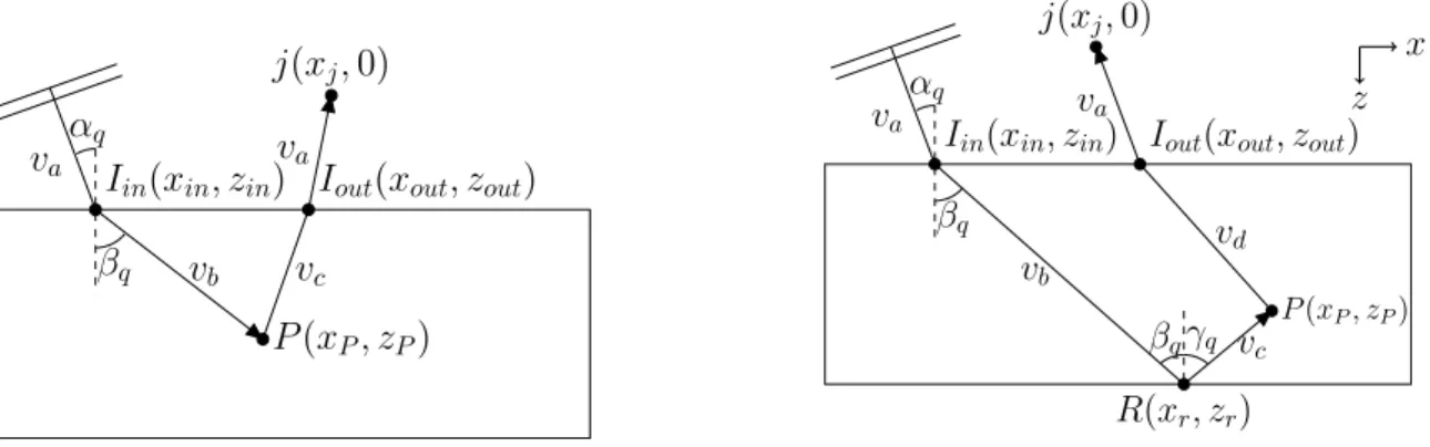
In direct mode, the ultrasonic wave propagates from the probe to the focusing point and back to a receiver, through the surface (cf Fig. 1a).
v
av
bv
cv
aα
qβ
qP (x
P, z
P)
I
in(x
in, z
in)
j(x
j, 0)
I
out(x
out, z
out)
x
z
v
av
bv
cv
dv
aα
qβ
qβ
qγ
q P (xP, zP)R(x
r, z
r)
I
in(x
in, z
in)
j(x
j, 0)
I
out(x
out, z
out)
Fig. 1. Path followed by a wave to reach a focusing point P in (a) direct mode and (b) half-skip mode imaging.
Assuming that the plane wave is transmitted in water with an angle αq, the impact point Iinon the surface can be
computed geometrically by xin= zintan αq. The time-of-flight tPq is given by:
tqP= xinsin αq+ zincos αq va + (xP− xin) sin βq+ (zP− zin) cos βq vb , (2)
where va is the wave velocity in water and vb and vcare the speeds of transmitted and backscattered waves in the
component. Depending on the imaging mode considered, vband vcmay correspond to longitudinal (L) or transverse
(T ) waves. The time-of-flight for the backscattered wave is determined by applying the Fermat principle and the iterative gradient descent method, that is feasible on plane and complex surfaces.
2.2. Half-skip mode imaging
In half-skip mode, there is a reflection on the backwall of the component (cf Fig. 1b). Therefore, there are two impact points (Iinand R) to determined in order to obtain the incident path. The impact point Iinon the surface is the
the time-of-flight tqpis obtained by: tPq = xinsin αq+ zincos αq va +(xr− xin) sin βq+ (zr− zin) cos βq vb + p (xr− xP)2+ (zr− zP)2 vc , (3)
where, compared to direct modes, vcrepresents here the speed of a wave reflected by the backwall. The backscattered
paths can be obtained as previously.
In case of an irregular geometry, the time-of-flight computation stays practically unchanged, the main difference lies in the determination of the delay law to transmit a plane wave under the complex interface.
3. Experimental results
3.1. Specimens with a plane surface
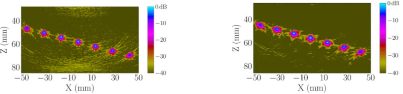
In the first experiment, a phased array probe (128 elements, 2MHz center frequency) is used in immersion to image a steel block specimen (100mm thickness) containing several side drilled holes (2mm diameter) at different depths. The LL direct mode (vb= vc= vLin Fig. 1a) is used to image the artificial defects. Figure 2 displays the STA image
obtained by firing the elements one by one (a), and the PWI image by transmitting 40 planes (from -60˚to 60˚) waves with a 3˚angular step (b). It can be observed that both images are similar with a Signal to Noise Ratio (SNR) around -35dB, but the PWI requires 3 times less transmissions than the STA method.
Fig. 2. Experimental images obtained with the (a) STA (128 transmissions). (b) PWI (40 transmissions).
In the second experiment, the PWI method has been applied to image a 10mm breaking notch at the backwall of a steel specimen (30mm thickness). The T T T half-skip mode (vb = vc = vd = vT in Fig. 1b) is used to fully image
the notch and improve its characterization. Figure 3 presents the STA image obtained with 64 transmissions (a), and the PWI image obtained with only 4 transmissions (from 43˚to 46˚). The number of transmissions is dramatically reduced in PWI imaging with a better SNR.
4 L´eonard Le Jeune/ Physics Procedia 00 (2015) 000–000
3.2. Specimen with a complex surface
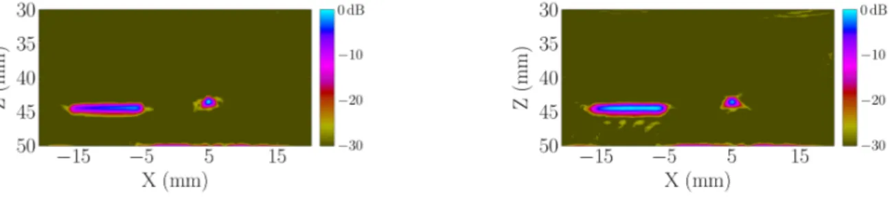
In the third and last experiment, a duraluminum specimen with a wavy surface is considered (cf Fig. 4). STA and PWI acquisitions have been performed in order to image a 6mm height (10mm width) notch and a 2mm diameter hole under the irregular surface. The STA image is obtained after 64 ultrasonic shots (the array is composed of 64 elements) while the PWI image is calculated by transmitting only 9 plane waves (from -20˚to 20˚). The results in Fig. 5 show a very good agreement between the STA (a) and the PWI (b) images, but with a considerably reduced number of transmissions for the PWI method.
Fig. 4. Aluminium specimen presenting an irregular surface.
Fig. 5. Experimental images obtained with the (a) STA (64 transmissions). (b) PWI (9 transmissions).
4. Conclusions and perspectives
In this communication, we have shown that the PWI method is very promising for NDT applications as it provides images with quality equivalent to the STA images but with fewer transmissions. The method has been evaluated and validated in case of plane and irregular surfaces, and by using direct or half-skip imaging modes. This work is undergoing generalization to calculate an image with several imaging modes, and to take into account a probe displacement during inspection.
References
[1] Montaldo G., Tanter M., Benech N., Fink M., (2009), Coherent plane wave compounding for very high frame rate ultrasonography, IEEE UFFC, Vol. 56, 489–506
[2] Iakovleva E., Chatillon S., Bredif P., Mahaut S., (2014), Multi-mode TFM imaging with artifacts filtering using CIVA UT forwards models, AIP Conference Proceedings, Vol. 1581, 72–79
[3] Chiao R. Y., Thomas L. J., Silverstein S. D., (1997), Sparse array imaging with spatially-encoded transmits, IEEE Ultrasonic symposium, vol. 2, 1679–1682