HAL Id: hal-00290121
https://hal.archives-ouvertes.fr/hal-00290121
Submitted on 24 Jun 2008HAL is a multi-disciplinary open access archive for the deposit and dissemination of sci-entific research documents, whether they are pub-lished or not. The documents may come from teaching and research institutions in France or
L’archive ouverte pluridisciplinaire HAL, est destinée au dépôt et à la diffusion de documents scientifiques de niveau recherche, publiés ou non, émanant des établissements d’enseignement et de recherche français ou étrangers, des laboratoires
Cavity Soliton Laser based on mutually coupled
semiconductor microresonators
Patrice Genevet, Stéphane Barland, Massimo Giudici, Jorge R. Tredicce
To cite this version:
Patrice Genevet, Stéphane Barland, Massimo Giudici, Jorge R. Tredicce. Cavity Soliton Laser based on mutually coupled semiconductor microresonators. Physical Review Letters, American Physical Society, 2008, 101 (123905), pp.123905. �10.1103/PhysRevLett.101.123905�. �hal-00290121�
Cavity Soliton Laser based on mutually coupled semiconductor
microresonators
P. Genevet, S. Barland, M. Giudici and J.R. Tredicce
Universit´e de Nice Sophia Antipolis,
Institut Non-Lin´eaire de Nice, UMR 6618,06560 Valbonne, France
(Dated: June 24, 2008)
Abstract
We report on experimental observation of localized structures in two mutually coupled broad-area semiconductor resonators. These structures coexist with a dark homogeneous background and they have the same properties as cavity solitons without requiring the presence of a driving beam into the system. They can be switched individually on and off by means of a local addressing beam.
Localized Structures (LS) form in large aspect-ratio media where two or several solutions coexist in the parameter space (see e.g. [1] for a recent review). Cavity Solitons (CS) are LS generated in a cavity filled with a non linear medium driven by a coherent injected field (holding beam, HB) where they appear as single bistable bright intensity peaks coexisting with a homogeneous background. Their existence and mutual independence in semiconduc-tors have been experimentally demonstrated in microcavities operated as optical amplifiers [2, 3] since a local perturbation in form of a beam coherent with the HB can be used for switching CS on and off independently [2, 4]. The possibility to control their location and their motion by introducing phase or amplitude gradients in the holding beam suggests their use as mobile pixels for all-optical processing units. Indeed, in the last decade, CS in semiconductor have attracted a growing interest since they combine the bistability and plasticity properties with the advantages of semiconductor media in terms of fast response and small size. The application potential of CS has been evidenced with some first-principle demonstration of new all-optical devices exploiting CS properties for optical memories [5] and delay lines [6]. Nevertheless, the tight conditions required for CS stability in present experimental schemes hinders their application to non prototypical devices. A radical sim-plification could be achieved implementing the concept of Cavity Soliton Laser, i.e. a device generating CS without an external injection beam. Some steps in this direction have been made recently with a scheme based on broad area VCSEL submitted to frequency selective feedback [7]. However, even if no HB is present it appears that the stability of localized structures in this case depends critically on feedback alignment and on the detuning be-tween the resonator and the external frequency selecting element. An alternative approach is provided by a laser with a saturable absorber (SA). Indeed, this system is among the first ones theoretically shown to possess the necessary ingredients for the generation of localized structures in optics, called in this case dissipative autosolitons [8]. While this initial work was realized in the limit of fast materials [8, 9], it was later extended to the case of finite relaxation times [9, 10]. Finally, the case of slow absorber material (as would be the case for semiconductors) was examined in [11] and the case where the absorbing and gain media have equal response times has been studied in [12]. The authors of these last references show numerically that in a vertical cavity surface emitting laser (VCSEL) with saturable absorber, CS related to the existence of a modulational instability can be switched on and off by injecting a local optical perturbation.
Despite this extensive theoretical and numerical research, we are not aware of any exper-imental observation of CS using a saturable absorber in semiconductor laser. In this letter we show the experimental realization of a CSL based on two mutually coupled micro res-onators where one plays the role of an amplifier and the second of a saturable absorber. As we shall demonstrate below, this scheme allows a remarkably simple realization of a cavity soliton laser. We show that bistable solitary structures coexist with a dark homogeneous background and that they can be switched on and off independently by an incoherent beam. We believe that this demonstration opens the way towards implementations in very compact monolithic devices including both the amplifying and saturable absorber sections [13].
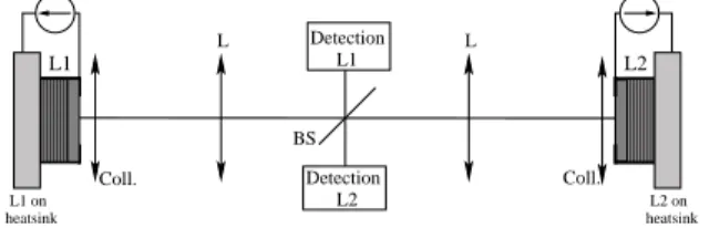
Detection 00000 00000 00000 00000 00000 00000 00000 11111 11111 11111 11111 11111 11111 11111 00000 00000 00000 00000 00000 00000 00000 11111 11111 11111 11111 11111 11111 11111 0000 0000 0000 0000 0000 0000 0000 1111 1111 1111 1111 1111 1111 1111 L Coll. L L2 L1 Coll. L1 on heatsink L2 on heatsink BS L2 L1 Detection
FIG. 1: Schematic drawing of the experiment. L1: Laser above the transparency, L2: Laser below the transparency, BS: beam splitter. Detection of L1(resp. L2) includes a CCD camera monitoring the near field of L1 (resp. L2) and a fast detector to monitor the local temporal behavior.
The lasers we use are two nominally identical VCSELs provided by ULM Photonics. They are oxydized bottom-emitter VCSELs emitting around 975nm [14]. Their transverse section is 200 µm. They are mounted in a mutually coupled configuration, where one laser is electrically biased above the transparency but below its standalone coherent emission
threshold (L1), while the other is biased below transparency (L2). Both devices packages
are temperature stabilized. In order to compensate the effects of diffraction during the propagation in the extended cavity (60 cm long) and to keep the system highly symmetric, we use identical collimators and identical lenses placed such that the two resonators are in a self imaging condition (see Fig. 1). This configuration allows to preserve the high Fresnel number required for the existence of LS [3]. A 20 % reflection beam splitter is inserted in the center of the cavity to extract two output beams from the system. Time-averaged near-field profiles of both resonators are simultaneously imaged on two charge-coupled device (CCD) cameras. The use of two CCD cameras allows to check the output of each element
of the coupled system independently. In the detection path of laser L1, an iris placed in
temporally resolved detection. A photodetector Thorlabs PDA8GS (less than 100 ps rise time) coupled to a digital oscilloscope LeCroy Wavemaster 8600A (6 GHz analog bandwidth)
monitors the output of this small portion of the L1 profile.
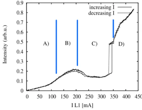
0 0.1 0.2 0.3 0.4 0.5 0.6 0.7 0.8 0.9 0 50 100 150 200 250 300 350 400 450 Intensity (arb.u.) I L1 [mA] increasing I decreasing I A) B) C) D)
FIG. 2: Local intensity output emit by the system when we scan IL1 for all the other parameters
constant (IL1 is drive very slowly to keep the temperature controller stable). A) below threshold,
B)lasing by feedback, C)Absorption by L2, bistable behavior, D) pattern formation.
The solitary VCSELs light intensity output as function of the pumping current (IL1,L2)
indicate that the uncoupled lasers have very similar standalone coherent emission thresholds Ith
L1 ∼ I th
L2 ∼ 400mA. The temperature control of each device is set such that the emission
wavelength of laser L1 is approximately 1 nm blue detuned with respect to laser L2 when
both devices are pumped by the same amount of current. In Fig. 2 we show the local intensity
output of the compound system as a function of pumping current of L1, (IL1), while IL2
is kept fixed at a few mA, i.e. below the transparency pumping value. The monitored region has a diameter of about 20 µm and it is placed in the centre of the device. When
IL1 ≤100 mA (zone A in Fig. 2, the increase of emitted power is attributed to spontaneous
emission, since the optical spectrum of the system does not show coherent emission. The
first threshold (Ith ∼ 100 mA, region B of Fig. 2) is reached when light linearly reflected
on the output mirror of L2 sufficiently reduces the losses of the compound system such that
laser emission can be obtained. At that point, threshold reduction and coherent emission may therefore be attributed to losses reduction as is shown in conventional optical feedback experiments.
For, IL1 ≥ 200mA (region C of Fig. 2) the power output of the compound system
resonances of both cavities match and absorption in device L2 takes place. The fact that the resonance frequencies of both devices match only for certain current values is due to the linear shift experienced by the laser frequency as a function of the pumping current due to
Joule heating. The absorption by laser L2 in region C of Fig. 2 has been verified by
per-forming the same measurement with laser L2 unpumped, which allows to verify the presence
of a light induced current through the device, which is absent in regions A or B. Increasing
further IL1, the intensity output remains constant at a low value. The optical spectra of
this low intensity emission shows a broad band peak indicating that this state corresponds
to spontaneous emission since absorption cut the feedback from L2. Further increase of
IL1 above a critical value I
c
L1 the local intensity jumps up to a high value. The optical
spectrum associated to this state shows a well pronounced peak red-detuned with respect the spontaneous emission peak observed in the low level state. In the near field profile this local transition of the intensity output corresponds to the formation of a bright single peak
structure inside the monitored area. For larger IL1 (region D of Fig. 2) the local intensity
keeps increasing, while the near field profile reveals the formation of multi peaked structures
and extended patterns around the monitored region. If IL1 is decreased the local intensity
shows hysteresis demonstrating bistability between a low and a high emitted intensity state in the region monitored by the detector.
We note that while the curve shown in Fig. 2 was obtained for a particular setting of the temperature of each device’s substrate, equivalent results may be obtained for different temperature and current settings provided a number of conditions are satisfied. First of
all, if device L2 is pumped at a too high value (that we interpret as above transparency??),
we made no observation of the bistable response of the system. Second, if L1 is initially
red detuned with respect to L2, these results won’t be observed since both devices won’t be
resonant for any current value of L1. The essential conditions are therefore an initial detuning
allowing for current induced tuning of L1 towards the resonance of L2 when L2 is kept in an
absorbing regime. An additional condition is that if the suitable tuning condition is obtained
for a too low value of pumping of device L1 (pumping of device L2 being kept constant) the
total amount of field in the compound system does not seem to reach the saturation value.
In this case, although the effects of absorption in L2 can clearly be identified, no bistable
behavior was observed. We expect however that this condition, related to the saturation
imaging of device L1 on device L2 in our setup or decreasing the reflectivity of the central beam splitter.
A detailed study of required conditions has been performed and will be presented else-where, but for now we underline that provided that the previous conditions are fulfilled, the curve shown on Fig. 2 can be obtained for different settings of device temperatures and
currents, with IL2 allowing to tune the amount of absorption in the system. As an order of
magnitude, the results presented here could be obtained for a broad range of temperature
settings leading to the bistability cycle being observed for currents in L2 ranging from 5 to
30 mA and currents in L1 ranging from 120 to 380 mA.
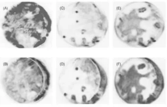
FIG. 3: Examples of near field of both devices. Dark areas correspond to high intensities. a)Near field of the high current laser (L1) before the interaction, b) Near field of the low current laser (L2) before the interaction (IL1 = 180 mA), c,d) Near field of L1 NF and L2 in the absorption zone
(IL1 = 358 mA), e,f) Near field of L1 and L2 when the pattern is developed (IL1 = 365 mA). L2
is slightly shifted on the left.
In Fig. 3 we show the near-field transverse profiles of L1 and L2 for different values
of IL1, while IL2 is kept constant at 15 mA. As discussed previously, in the self imaging
scheme configuration, L1 and L2 are placed on self-conjugate planes with a magnification
of one. In order to monitor the absorption, the devices are slightly shifted with respect to each other in the horizontal direction. This way, a small portion close to the border of
L1 will not interact with the corresponding portion of L2 and it will be simply reflected
back by the substrate of the device. When IL1 is below the compound system’s threshold
both profiles (not shown) are homogeneous. When IL1 is increased above the first threshold
(corresponding to region B in Fig. 2, we observe the formation of complex and in general
L1 (Fig. 3 a),b)). In Fig. 3, b) showing the near field profile of L2, the dark area in the
rightmost part of the image corresponds to high intensity emitted by L1 and reflected by
the substrate of the device L2 due to the lateral shift we introduced. The bright arc nearby,
closer to the center, corresponds to the edge of L2.
Keeping increasing IL1 the two resonators start to interact with L2 absorbing the field
emitted by L1 (region C of Fig. 2) and the near field profile of both lasers is mostly dark and
homogeneous except for the small portion close to the rightmost edge, due to reflection onto
the substrate of L2. By increasing the current IL1 above I
c
L1, bistable bright spots appear
spontaneously (see Fig. 3 C, D).
Further increase of IL1 leads to the formation of generally nonstationary filaments
con-necting the isolated spots together. For higher values of IL1 (Fig. 3 E and F), corresponding
to region D of Fig. 2), a complex pattern develops progressively through the whole transverse section. Temporally resolved detection reveals that the widely spread pattern is generally not stationary and exhibits complex dynamics.
When the parameters are set in region C of figure 2, the observed bright isolated spots (Fig. 3, C, D) are candidates for an interpretation in terms of CS, since they coexist with a
homogeneous background as shown by the hysteretical behavior as a function of IL1 (Fig.2.
While they appear rather uncorrelated one to the other on the near field images, the full demonstration of their mutual independence can only be performed by switching them on and off with a local perturbation. Indeed, it has been shown numerically that localized states in a cavity soliton laser can be switched on or off by a coherent [11, 12] or incoherent [15] local optical perturbation. In our experiment, we use a coherent beam whose optical frequency is close (here, within 0.1 nm) to the emission frequency of the coupled device and whose diameter is about 15 µm. This beam is obtained from an external-cavity tunable laser
in Littman configuration and applied on device L2. By means of this local optical injection,
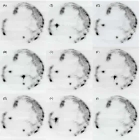
we are able to demonstrate independent switching of localized structures as shown on Fig. 4. The system is prepared in the low level emission state with the parameters set in the bistable region. Starting with no spot, applying the WB to a point in the transverse plane
of L2, we generate a high intensity spot with a diameter of the order of 10µm. We then
remove the WB and the bright spot remains on indefinitely. We then apply the WB at a dif-ferent position and a second spot is generated without disturbing the first one, provided the distance between the two spots is sufficient (no distance smaller than 40 µm was observed).
FIG. 4: L1 near field intensity distribution. Dark areas correspond to high intensities. Sequence of successive switching of two independent structures with an incoherent WB tuned at the CS wavelength with all parameter fixed. a) Both structures are off, b) The injection of WB switches one structure, c) the structure remains on after the WB is blocked, d) the injection of the WB at a second location ignites a second structure, e) when the WB is blocked, both structures are on, f) reapplying the WB in the vicinity of the second structure attracts it to a slightly different location, g) when the WB is blocked the structure switches off, h) the WB is applied in the vicinity of the first structure to attract it to a slightly different location, i) when the WB is blocked, both structures are off.
The two spots stay on even after the WB is removed. We note that, as in previous exper-iments in semiconductor devices [4, 7], local device inhomogeneities seem to play a role in the stabilization of localized states since although it is possible to observe stable structures in different positions, not all positions appear to be stable. We make use of this to switch off the localized structures. In experiments involving an external forcing by a holding beam, the simplest procedure is to apply a coherent local perturbation with opposite phase with respect to the holding beam. In the present case, this approach is not possible. Therefore we take advantage of mobility properties of the structures to switch them off: by applying the same perturbation as before close to a CS, we can drag it to a region of space where it is unstable and therefore switches off (Fig. 4, F, H). It is also possible to switch off the structures without dragging them outside of their preferred location if the pumping current of each device is set such that the system is very close to the lower edge of the bistability
region for the structure under consideration. In this case though, our optical perturbation did not appear to be sufficient to switch on a localized structure. Conversely, if the system parameter were set very close to the upper edge of the bistability region, it was not possi-ble to switch localized structures off, except with the dragging procedure described above. While the application of the local perturbation was quasi continuous in the measurements shown above, numerical simulations performed on a model for a monolithic semiconductor laser with saturable absorber [15] indicate the possibility of ns switching time. Preliminary experimental observations indicate that perturbations as short as 100 ns (limited by the modulator) can be sufficient to switch on or off a localized structure, although no optimiza-tion (e.g tuning and power of the writing beam) has been performed yet.
In conclusion, we have given evidence of single localised peaks that fulfill all the criteria required to be interpreted as cavity solitons in a compound semiconductor laser system with a saturable absorber. Since no injection beam is present in our experiment we believe it is a very promising realization of a semiconductor cavity soliton laser. One of the greatest strengths of this experiment is its possibly straightforward miniaturization to monolithic devices able to generate self localized, bistable and mobile laser beams. In the present version of the system, the observation of spatially localized periodically pulsed transient regimes suggests the suitability of the system to the generation of three dimensional localized structures.
This work was supported by the FET Open Project FunFACS (www.funfacs.org). We are grateful to L. Gil, L. Columbo and G. Tissoni for many useful discussions.
[1] N. Akhmediev and A. Ankiewicz, eds., Dissipative solitons, vol. 661 of Lecture Notes in Physics (Springer Berlin / Heidelberg, 2005).
[2] S. Barland, J. Tredicce, M. Brambilla, L. A. Lugiato, S. Balle, M. Giudici, T. Maggipinto, L. Spinelli, G. Tissoni, T. Kn¨odel, et al., Nature 419, 699 (2002).
[3] L. Lugiato, IEEE J. Quantum Electron 39, 193 (2003).
[4] X. Hachair, S. Barland, L. Furfaro, M. Giudici, S. Balle, J. R. Tredicce, M. Brambilla, T. Mag-gipinto, I. Perrini, G. Tissoni, et al., Phys. Rev. A p. 43817 (2004).
89, 221111 (2006).
[6] F. Pedaci, S. Barland, E. Caboche, P. Genevet, M. Giudici, J. Tredicce, T. Ackemann, A. Scroggie, W. Firth, G.-L. Oppo, et al., Applied Physics Letters 92, 011101 (2008).
[7] Y. Tanguy, T. Ackemann, W. J. Firth, and R. J¨ager, Physical Review Letters 100, 013907 (2008).
[8] N. Rosanov and S. Fedorov, Opt. Spectrosc. 72, 782 (1992).
[9] N. N. Rosanov, Spatial Hysteresis and Optical Patterns (Springer-Verlag, Berlin, Heidelberg, New York, 2002).
[10] S. V. Fedorov, A. G. Vladimirov, G. V. Khodova, and N. N. Rosanov, Phys. Rev. E 61, 5814 (2000).
[11] M. Bache, F. Prati, G. Tissoni, R. Kheradmand, L. Lugiato, I. Protsenko, and M. Brambilla, Applied Physics B 81, 913 (2005).
[12] F. Prati, P. Caccia, G. Tissoni, L. Lugiato, K. Mahmoud Aghdami, and H. Tajalli, Applied Physics B 88, 405 (2007).
[13] A. J. Fischer, K. D. Choquette, W. W. Chow, H. Q. Hou, and K. M. Geib, Applied Physics Letters 75, 3020 (1999).
[14] M. Grabherr, R. J¨ager, M. Miller, C. Thalmaier, J. Herlein, and K. Ebeling, IEEE Photon. Tech. Lett. 10, 1061 (1998).
[15] K. Mahmoud Aghdami, F. Prati, P. Caccia, G. Tissoni, L. Lugiato, R. Kheradmand, and H. Tajalli, The European Physical Journal D 47, 447 (2008).