HAL Id: hal-01873064
https://hal.archives-ouvertes.fr/hal-01873064
Submitted on 12 Sep 2018
HAL is a multi-disciplinary open access
archive for the deposit and dissemination of
sci-entific research documents, whether they are
pub-lished or not. The documents may come from
teaching and research institutions in France or
abroad, or from public or private research centers.
L’archive ouverte pluridisciplinaire HAL, est
destinée au dépôt et à la diffusion de documents
scientifiques de niveau recherche, publiés ou non,
émanant des établissements d’enseignement et de
recherche français ou étrangers, des laboratoires
publics ou privés.
Fast and easy preparation of
few-layered-graphene/magnesia powders for strong, hard
and electrically conducting composites
Alicia Weibel, David Mesguich, Geoffroy Chevallier, Emmanuel Flahaut,
Christophe Laurent
To cite this version:
Alicia Weibel, David Mesguich, Geoffroy Chevallier, Emmanuel Flahaut, Christophe Laurent. Fast
and easy preparation of few-layered-graphene/magnesia powders for strong, hard and electrically
con-ducting composites. Carbon, Elsevier, 2018, 136, pp.270-279. �10.1016/j.carbon.2018.04.085�.
�hal-01873064�
To cite this version :
Weibel, Alicia and Mesguich, David and Chevallier,
Geoffroy and Flahaut, Emmanuel and Laurent, Christophe Fast and easy
preparation of few-layered-graphene/magnesia powders for strong, hard and
electrically conducting composites. (2018) Carbon, 136. 270-279. ISSN
0008-6223
O
pen
A
rchive
T
OULOUSE
A
rchive
O
uverte (
OATAO
)
OATAO is an open access repository that collects the work of Toulouse researchers and
makes it freely available over the web where possible.
This is an author-deposited version published in :
http://oatao.univ-toulouse.fr/
Eprints ID : 20140
To link to this article: DOI : 10.1016/j.carbon.2018.04.085
URL :
http://doi.org/10.1016/j.carbon.2018.04.085
Any correspondence concerning this service should be sent to the repository
administrator:
staff-oatao@listes-diff.inp-toulouse.fr
Fast and easy preparation of few-layered-graphene/magnesia
powders for strong, hard and electrically conducting composites
Alicia Weibel
a, David Mesguich
a, Geoffroy Chevallier
a,b, Emmanuel Flahaut
a,
Christophe Laurent
a,*aUniversit!e de Toulouse, CIRIMAT, CNRS-INPT-UPS, Universit!e Paul-Sabatier, 118 Route de Narbonne, F-31062 Toulouse Cedex 9, France bPlateforme Nationale CNRS de Frittage Flash, PNF2, MHT, Universit!e Paul-Sabatier, 118 Route de Narbonne, F-31062 Toulouse Cedex 9, France
a b s t r a c t
Composite powders were prepared by the chemical vapor deposition (CH4/Ar atmosphere) of carbon in the form of 2e8 layers few-layered-graphene (FLG) covering the MgO powder grains, without any mixing step. The composites were consolidated to nearly full (99%) density by spark plasma sintering with no or little damage to the FLG. The FLG is located along the MgO grain boundaries, as opposed to be dispersed as discrete particles or flakes. This causes a dramatic hindrance of the MgO grain growth, the average grain size being considerably lower for the sample with 2.08 vol% carbon (200 nm) than for pure MgO (3.7mm). The samples are investigated by Raman spectroscopy, scanning and transmission electron
microscopy. The composites are electrically conducting with a percolation threshold below 0.56 vol%. Compared to pure MgO, the composites are simultaneously stronger (345 vs 200 MPa) and harder (9.8 vs 3.8 GPa). This could arise from reinforcement mechanisms such as crack-deflection and crack-bridging by FLG, but also from MgO grain refinement.
1. Introduction
Graphene/ceramic composites are focusing worldwide atten-tion because they allow combining some very attractive electrical, thermal and mechanical properties as described in recent reviews of the field [1e4]. The matrices investigated include borides (ZrB2
[5]), carbides (B4C [6], SiC [7e10], TiC [11], TaC [12,13]), nitrides
(AlN [14e17], Si3N4[18e22], TiN [23]) and oxides (MgO [24], Al2O3
[25e33], SiO2[34], ZrO2[35] and hydroxyapatite [36,37]). Many
processing methods involve the preparation of graphene/ceramic powders followed by a consolidation step performed by a variety of techniques including pressureless sintering, spark plasma sin-tering, hot pressing and hot isostatic pressing. One common feature of several methods used to prepare the graphene/ceramic powders, such as the powder processing route, colloidal pro-cessing, salt precursor method and molecular mixing method, is that they involve pre-existing graphene agglomerates prepared from graphite. Therefore, the carbon in the composites is not present as pristine single-layer graphene (SLG), but rather as
few-layered-graphene with 2e10 layers (FLG), or a mixture of SLG and FLG, or also as stacks up to about 100 nm thick, denoted as phene nanosheets (GNS), graphene nano-platelets (GNP), gra-phene platelets (GPL) or even graphite platelets. Other important points to take into account are the lateral dimensions of the platelets and the amount of defects within, sometimes repre-sented as the carbon/oxygen (C/O) ratio [38]. Indeed, the chemical exfoliation of graphite [39,40] produces defective graphene oxide (GO), which is readily dispersed in water and organic media but may not show the desired properties of graphene. GO may have to be reduced to partially eliminate some defects in the so-obtained reduced-graphene oxide (r-GO). As a typical example, Fan et al. [28] used GO flakes prepared by a lengthy procedure involving the treatment of graphite by solutions of H2SO4and KMnO4(magnetic
stirring, 2 h), H2O2(decantation, a few hours), washing with HCl
solution, vacuum filtration (several times), dialysis for a week, sonication and centrifugation (4000 rpm for 30 min) and these authors readily admit that the elastic properties of their FLG have been deteriorated severely by oxidation and reduction. The me-chanical exfoliation of graphite [41] is also used for the prepara-tion of GNS and GNP samples. It involves applying shear forces by using high-energy ball-milling or sonication which may also decrease the lateral dimensions of the platelets and even
introduce contamination or undesirable structural defects. Moreover, the yield is of the order of 1%. Moreover, it is most important to note that the preparation of the graphene/ceramic powders still involves many further steps. For example, GNS/MgO composites [24] were prepared by a mixing route involving son-ication of a graphene slurry, milling of a MgO slurry using ZrO2
balls, mixing the two slurries, another cycle of grinding, filtration, drying, sieving, and hot-pressing. As opposed to these routes, in situmethods have been proposed for the formation of graphene/ SiC composites, consisting either in the epitaxial graphene growth on SiC grains during the densification by spark plasma sintering (SPS) [42] or in the nucleation of a graphene network from a Si-preceramic polymer such as a polysilazane, polysiloxane or pol-ycarbosilane during sintering at high temperatures [43,44]. Here, we report a fast and easy, one-step, route for the production of graphene/ceramic powders, which does not require pre-existing graphene or any mixing step and can be applied to many different ceramics or even metals. It is based on the chemical vapor deposition (CVD) of FLG through the decomposition of a carbon containing gas (methane) onto a ceramic powder and the sintering of the so-obtained powder. It is analogous to a route reported earlier for the direct synthesis of carbon nanotubes within a ceramic powder [45e52], only simpler because it does not involve any transition metal catalyst. Aside from the field of catalysis where accumulation of carbon on the surface of solid catalysts is a well-known poison, the deposition of carbon onto metal and oxide powders has already been reported, as FLG [53,54], heavily distorted graphene layers [55] or ultra-thin (1e5 nm) graphitic carbon layers [56] but to the best of our knowledge it has not been reported specifically for the production of graphene/ceramic composites. The present sintered FLG/MgO samples show strengthening and hardening compared to pure MgO as well as a very low electrical percolation threshold. The microstructure and properties will be compared to those of GNS/ MgO composites [24] and double-walled carbon nanotube (DWCNT)/MgO composites [52].
2. Experimental methods 2.1. Powders synthesis
A commercial MgO powder (Sigma Aldrich, > 99.9%, 100 ± 30 nm) was divided into four batches. Three of them were submitted to the CVD treatment performed in order to decompose a carbon-containing gas (CH4) onto the MgO grains. The samples
(12 g) were heated in argon (10 L/h) up to 900!C (15!C/min) and
upon reaching this temperature CH4was introduced (1, 2.5 and
5 L/h, respectively, while keeping the total gas flow-rate equal to 10 L/h). The flow-rates were monitored using mass-flow control-lers. A dwell time of 1.25 h was applied at 900!C. Cooling down to
room temperature was performed in the same CH4/Ar
atmosphere.
2.2. Spark plasma sintering
The MgO and composites powders were consolidated by SPS (Dr. Sinter 2080, SPS Syntex Inc., Japan). The samples (about 3.2 g) were loaded into a 20 mm inner-diameter graphite die. A sheet of graphitic paper was placed between the punch and the powder and between the die and the powder for easy removal. This ensemble is known as the stack. The powders were sintered in vacuum (residual cell pressure < 10 Pa). A pulse pattern of twelve current pulses
Table 1
Characteristics and properties of the specimens: CVD atmosphere (CH4/Ar), carbon content (Cnand Cv) measured for the powders, Raman ID/IGand I2D/IGratios for the powders
and dense samples.
Sample CH4/Ar Cn Cv ID/IG I2D/IG ID/IG I2D/IG
L/h/L/h wt.% vol% powder powder dense dense
MgO 0/10 0 0 e e e e
G56 1/9 0.33 0.56 0.6 ± 0.2 0.42 ± 0.04 1.0 ± 0.1 0.2 ± 0.1
G193 2.5/7.5 1.14 1.93 1.74 ± 0.05 0.35 ± 0.05 1.50 ± 0.04 0.30 ± 0.03
G208 5/5 1.23 2.08 1.49 ± 0.02 0.17 ± 0.02 1.56 ± 0.07 0.21 ± 0.01
followed by two periods of zero current was used. An optical py-rometer, focused on a little hole at the outer surface of the die, was used to control the temperature. A heating rate of 300!C/min was
used from room temperature to 600!C, where a 1 min dwell was
applied in order to stabilize the temperature reading of the py-rometer, which has a detection threshold of 580!C. Then, the
temperature was raised (100!C/min) to 1300!C, where a 3 min
dwell was applied. A uniaxial load was applied in 1 min (from 1000 to 1100!C) and maintained until the end of the dwell. The
corre-sponding uniaxial pressure is equal to 150 MPa. A cooling rate of 100!C/min was applied down to room temperature and the
uni-axial load was gradually released during the same time. Note that in the SPS process, there is no resistor surrounding the stack as in hot-pressing. The temperature ramp is regulated by the electrical cur-rent program and it is thus possible to regulate the cooling of the stack through the electrical current program because there is no thermal inertia of the chamber. The sintered specimens were in the form of pellets 20 mm in diameter and about 3 mm thick. The graphitic paper remaining on the surface was removed by machining. Carbon diffusion into the sample is estimated to be no
more than 100
m
m deep because of the short SPS thermal cycle. About 250m
m are machined of each side of a pellet before furthercharacterization and testing in order to avoid this issue. 2.3. Characterization
The carbon content in the powders was measured by the flash combustion method with an accuracy of ±2% (standard deviation calculated on ten measurements). The density of all specimens was measured by Archimedes' method. The relative density was calculated using 3.58 g/cm3for MgO and 2.1 g/cm3 for graphene.
Selected samples were observed by field-emission-gun scanning electron microscopy (FESEM, JEOL JSM 6700F and 7800F) and transmission electron microscopy (TEM, JEOL JEM 2100F). The samples were coated with platinum (a few nanometers thick) prior to FESEM observations, in order to increase the contrasts. For the G208 sintered sample, a thin foil for TEM observations was pre-pared using a routine involving grinding with SiC paper, dimpling (GATAN 656) with a 1
m
m diamond suspension and cold ion millingat 4 kV (GATAN PIPS 691). Raman spectra were recorded at
632.82 nm (LabRAM 800, Jobin-Yvon) and they were averaged on three spectra. The electrical conductivity was measured at room temperature with direct currents applied on (1.8 " 1.8 " 5 mm3) specimens, parallel to their length, i.e. perpendicular to the SPS pressing axis. A 2-probe method was used. A silver paste was applied on the 1.8 " 1.8 mm2sections at the tips of the test samples in order to connect the conducting electrodes. The current densities used were lower than 160 mA/cm2(Keithley 2400). The indentation
tests (200 g (1.96 N) for 10 s in air at room temperature) were performed on the polished surface of the specimens by loading with a Vickers indenter (Mitutoyo HM 2000). The values reported are the average of 10 measurements. The transverse fracture strength (
s
f) was measured, parallel to the SPS pressing axis, by thethree-point bending method (Material Testing Systems MTS 1/M) on specimens about 1.8 " 1.8 " 18 mm3. The span between the two supporting pins is equal to 13 mm. Cross-head speed was fixed at 0.1 mm/min. The values reported are the average of measurements conducted on seven or eight specimens.
3. Results and discussion 3.1. Powders
The carbon content (Cn-Table 1) in the powders is equal to 0.33,
1.14 and 1.23 wt% for the samples prepared using 1, 2.5 and 5 L/h of CH4, respectively. Using 2.1 and 3.58 g/cm3 for the densities of
graphene and MgO, respectively, the carbon content is equal to 0.56, 1.93 and 2.08 vol% for the samples prepared using 1, 2.5 and 5 L/h of CH4, respectively. For the sake of brevity, these powders
will be denoted hereafter as G56, G193 and G208, respectively. A typical FESEM image (Fig. 1a) shows the 100e200 nm MgO primary grains forming agglomerates. Graphene platelets were not observed on such images. They were not observed either on low-magnification TEM images of the primary grains (Fig. 1b). Both images (Fig. 1) are from G56 but the G193 and G208 powders look exactly the same.
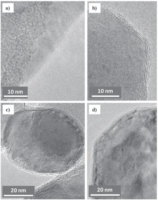
Higher-magnification TEM images (Fig. 2) reveal that for all three powders, which still could not be distinguished from each
other, the surface of the MgO crystals is covered by a few graphene layers, evaluated in the range 2e8 layers. This is in agreement with earlier results [53] reporting the encapsulation of MgO nano-crystals by graphitic nanostructures and showing that changing the carbon feedstock (ethanol or CH4), oxide (SiO2, Al2O3, MgO, Ga2O3),
crystal size or increasing the reaction time does not alter the number of graphitic layers (1e8). Changing the composition of the gas atmosphere, for a given carbon source, was not reported in Ref. [53].
A high-resolution TEM (HRTEM) image of G208 (Fig. 3) reveals the (200) planes of the MgO lattice and 2e3 graphene layers at the surface. According to these observations (Figs. 2 and 3), the amount of disorganized carbon that may be present in the powders should be very low and we do not expect that it may have any significant influence on the properties of the final material.
In order to observe only the carbon species, MgO was dissolved
Fig. 3.HRTEM image of G208 revealing the (200) planes of the MgO lattice and 2e3 graphene layers at the surface.
Fig. 4.TEM images after a mild acid treatment dissolved MgO, showing graphene in the form of curved carbon veils (some are arrowed).
by a mild acidic treatment by soaking the powder overnight in an HCl aqueous solution (36%, room temperature) [57] and the solid residues obtained after filtering and drying were observed by TEM (Fig. 4). Typical images show graphene in a form that could be described as carbon veils or a crumpled FLG particle, with marked curvatures (arrowed in Fig. 4) which could reveal that it was wrapped, at least partly, around the MgO grains, in agreement with observations of other acid-treated samples [53,58]. Obviously this is very different from the classical CVD deposition on planar sub-strates where the graphene domain size can be easily measured.
The Raman spectra of the FLG/MgO powders (Fig. 5) are normalized with the G band at 100%. The high-frequency range of the spectra shows the D band (ca. 1320 cm#1), the G band (ca.
1580 cm#1) and the 2D band (ca. 2650 cm#1).
The Raman spectrum of the MgO powder is also shown. It is dominated by two bands of roughly the same intensity, at about 1557 and 1930 cm#1. The band at 1557 cm#1could overlap with the
carbon G band in the other spectra. Note also that a fairly weak MgO peak is superposed with the carbon D band. However, a comparison of the MgO spectrum with the spectra for G56, G193 and G208 could indicate that the contribution of MgO to these spectra is very weak. The ID/IGratio for G56 has a large uncertainty (0.6 ± 0.2) but
is significantly lower than for G193 (1.74 ± 0.05) and G208 (1.49 ± 0.02), a higher value denoting more disorder (Table 1). An ID/IG ratio equal to about 1.67 was reported [53] for FLG/MgO
samples with 1e8 graphene layers (mostly 2e5), which is fairly close to the present values for G193 and G208. Therefore, these results could indicate that, for G56, the carbon was deposited in forms closer to BLG than 5e10 layers graphene, which would be in agreement with using a CVD atmosphere poorer in CH4. However,
the MgO powder grains are faceted and this could provoke the formation of defects (kinks) in the deposited FLG and thus the
proportion of defects could also be higher for G56. Fine-tuning the CVD conditions could provide a greater control. The 2D band po-sition for G56 at about 2650 cm#1is similar to a value reported for
bilayer graphene (BLG) investigated at the same wavelength [59]. The 2D band position for G193 and G208 (2620 and 2602 cm#1, respectively) is downshifted compared to the previous one and also to values commonly observed for FLG with 5e10 layers [59]. This could result from the presence of strains within the FLG stacking. Indeed, a downshift of the 2D band with increasing strain was re-ported for a graphene monolayer [60,61]. The I2D/IGratio for G56,
G193 and G208 is reported inTable 1. It is a complex contribution from the number of graphene layers, the stacking order and the defects [59,62] and precise determination requires measurements with two different excitation energies or by carefully comparing weaker combination Raman modes [62], which is outside the scope of this work.
3.2. Dense samples
The sintered specimens are denoted like the corresponding powders. The relative density of all specimens is equal to 99 ± 1%. The Raman spectra are reported inFig. 6. The spectrum for G56 only reveals weak D, G and 2D bands of FLG in addition to stronger MgO bands and thus the contribution of MgO to the G56 spectrum is important. The spectrum for pure MgO was subtracted from the G56 spectrum and the resulting spectrum (noted G56-MgO in
Fig. 6) shows the D, G and 2D bands as well as some other bands (1083 and 1520 cm#1 for example) that we did not attempt to
identify. A band at 1083 cm#1was observed for carbon-implanted
highly oriented pyrolytic graphite [63]. The spectra for G193 and G208, both normalized with the G band at 100%, still show the main MgO peak at 1500 cm#1. Note that this value is downshifted
compared to that for the MgO powder (1557 cm#1), thus causing
much less overlap with the G band.
The ID/IGvalues were calculated (Table 1) and the one obtained
for the (G56-MgO) subtracted spectrum (1.0 ± 0.1) is significantly
G56
G193
G208
Frequency (cm
-1)
0,00
0,50
1,00
1,50
2,00
2,50
3,00
3,50
4,00
4,50
5,00
1000
1500
2000
2500
3000
MgO
D
G
2D
In
te
n
si
ty
(a
.u
.)
Fig. 5.Raman spectra of the MgO powder and FLG/MgO powders (G56, G193 and G208). The dashed lines are guides to the eye. (A colour version of this figure can be viewed online.) G56 G193 G208 Frequency (cm-1) MgO D G 2D In te n si ty (a .u .) 0 50 100 150 200 250 300 350 400 450 500 1000 1500 2000 2500 3000 G56-MgO
Fig. 6.Raman spectra of the MgO and FLG/MgO samples (G56, G193 and G208) sin-tered by SPS. The subtraction of the G56 and MgO spectra (noted G56-MgO) is also shown. The dashed lines are guides to the eye. (A colour version of this figure can be viewed online.)
lower than those obtained for G193 (1.50 ± 0.04) and G208 (1.56 ± 0.07), although the difference is not as marked as for the corresponding powders. The I2D/IG values (Table 1) are also in
agreement with the values found for the powders although there is a higher uncertainty. Variations in the 2D band position, 2640-2650 cm#1for G193 and G208 and 2620 cm#1for G56 (determined
on the subtracted spectrum) could reflect variations in the presence of strains within the FLG stacking as noted above.
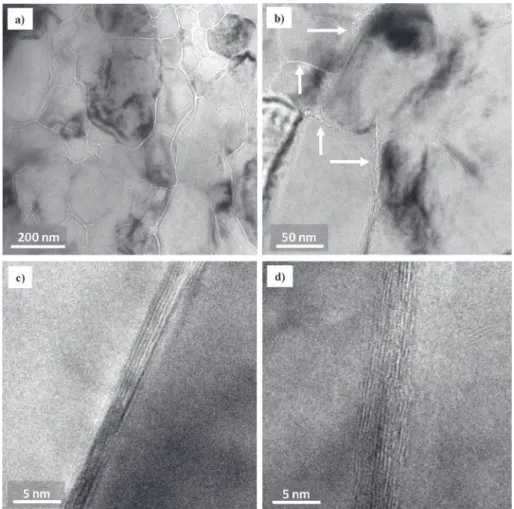
TEM observations of a thin foil of the G208 specimen (Fig. 7a and b) show MgO grains about 200 nm in size separated by sharp grain boundaries, appearing in white contrast on the images and also an interphase present at all grain boundaries (arrowed inFig. 7b). HRTEM images of the grain boundaries (Fig. 7c and d) indeed reveal fringes corresponding to fairly well-organized FLG about 2e5 nm thick. The number of graphene layers at the grain boundaries is thus ranging from 6 to 12, which is a reasonable agreement with twice the number of graphene layers, the FLG-covered MgO grains in the corresponding G208 powder (Fig. 2c and d) being side to side in the dense sample. High-magnification grain boundaries images similar to the present ones (Fig. 7c and d) have been reported for GNS/MgO samples [24], showing that the interface with MgO is not different if the carbon is in the form of FLG or GNS, at least at the scale of the GNS length. These observations confirm the above Raman spectroscopy results revealing no or little damage to the FLG upon sintering by SPS.
The fracture surfaces of the samples (Fig. 8) were observed by FESEM. The average MgO matrix grain size (d -Table 2), determined from such images, is equal to 3.7
m
m for MgO (Fig. 8a). The averageMgO matrix grain size is lower (2.1
m
m) for G56 (Fig. 8b) and very significantly lower (200e225 nm) for both G193 (Fig. 8c) and G208 (Fig. 8d), which could show that the graphene layers around the MgO grains hamper the motion of grain boundaries during sinter-ing and thus strongly limit matrix grain growth, in agreement with earlier results on graphene-ceramic composites [1e4,28,33,45,46]. The direct formation of FLG on the powder grains appears to be much more efficient than the addition of GNS to limit grain growth. Indeed, for GNS/MgO specimens, the MgO grain size only decreased from 25 to 10m
m upon addition of 7 vol% carbon [24]. This couldreflect the continuous-film nature of the present FLG as opposed to discrete particles dispersed within a matrix otherwise free of car-bon. These images and higher-magnification images reveal a transgranular-intergranular mixed fracture mode for MgO (Fig. 8e). For G56, the fracture mode is intergranular and some areas are covered by a relatively large carbon coating, extending over several
m
m2(Fig. 8f). This could correspond to the graphene layers forming an extended film over several MgO grains, possibly thicker than elsewhere in the sample, which could act as a defect and thus be observed on the fracture surface. This would be in qualitative agreement with a report for 1.5 vol% GPL-Si3N4samples [18], whereGPL wrapping and anchoring themselves around the individual Si3N4grains, form in some regions a single layer (or possible few
layers) veil of graphene that drapes over the fracture surface. This extended film is however not continuous, which could explain that grooves are observed on the image (arrowed inFig. 8f). For G193, areas covered by a carbon film are also faintly observed (upper right part ofFig. 8c) but higher-magnification images for G193 (Fig. 8g)
Fig. 7.TEM images (a, b) of a thin foil of the G208 specimen sintered by SPS and HRTEM images (c, d) of the grain boundaries. Arrows point to an interphase present at all grain boundaries.
and G208 (Fig. 8h) are thought to show the MgO surface covered by a film of graphene which cannot be identified in the FESEM images. For all three samples, there are some areas where FLG is observed in a transverse orientation (arrowed inFig. 8f, g, h). Note that the Pt-coating a few nanometers thick used for SEM samples preparation results in an overestimation of the FLG thickness. There is obviously no particular orientation with respect to the pressing axis, unlike in composites prepared by mixing GNPs or GNSs with the matrix powder or precursor, where the GNPs or GNSs are mostly aligned in the plane perpendicular to the pressing direction [1e4,24].
The electrical conductivity (
s
e - Table 2) of the composites, measured perpendicular to the pressing axis, increases upon the increase in carbon content, reaching 3.80 S/cm for G208. Note that the value for G56 (0.12 S/cm) shows that the percolation threshold is below 0.56 vol%, in line with data reported for fillers with a high aspect ratio, such as exfoliated GO/Al2O3 [27] and CNT-MgAl2O4[64] composites (0.38 and 0.64 vol%, respectively). This could again confirm that the carbon in the present samples is in the form of FLG film extending well over the MgO grain boundaries. For GNS/Al2O3
samples with a GNS thickness in the range 2.5e20 nm, the
Fig. 8.FESEM images of the fracture surface of the specimens prepared by SPS: a) MgO; b) G56; c) G193 and d) G208. Higher-magnification images: e) MgO; f) G56; g) G193 and h) G208. A carbon film is arrowed inFig. 8c. Dotted arrows inFig. 8f point to grooves in the FLG film. Solid arrows inFig. 8f, g, h point to the FLG observed in a transverse orientation.
percolation threshold was found around 3 vol% [26]. By contrast, for GNP/Si3N4, the percolation threshold was found [3,65] to be
significantly higher, 7.3 and 8.7 vol% (measures perpendicular and parallel to the SPS pressing axis, respectively), in very good agree-ment with the geometrical percolation threshold of randomly distributed overlapping ellipsoids with an aspect ratio of 10. Note that the conductivity values measured in the perpendicular direc-tion (with respect to the SPS pressing axis) by other authors were found to be higher than those measured in the parallel direction in the case of SiC [10] and Si3N4[65] but where found to be the same
in the case of AlN [17] and Al2O3[33].
The transverse fracture strength (
s
f-Table 2) is similar for MgO,G56 and G193 (about 200 MPa) but is higher (345 MPa) for G208. It is still unclear why there such a difference between G193 and G208 and further work is warranted. The value for G208 (345 MPa) is higher than those reported for GNS/MgO (265 MPa) [24] and DWCNT/MgO composites (276 MPa) [52] with similar carbon con-tents (2 and 2.3 vol%, respectively). Using the present method, the FLG is wrapped around the MgO grains in the powders (Figs. 2 and 3) and is located along the grain boundaries in the dense samples (Fig. 7), as opposed to be dispersed as discrete particles This could provide a stronger interfacial bonding than between GNS clusters and MgO, for which a poor interfacial bonding was reported [24]. The Vickers microhardness (HV -Table 2) of the three composites (8.0e9.8 GPa) is significantly higher than that of MgO (3.8 GPa). This could mostly reflect the much lower MgO grain size noted above, as was also observed for DWCNT-MgO composites [52] prepared by SPS (1650!C, 5 min) of a powder within which the
DWCNTs were grown directly. By contrast, no evolution or only a small microhardness decrease is reported upon the increase of carbon content when there is only a minor decrease in matrix grain size [24,28,33,66]. Fan et al. [28] concluded that it is reasonable to expect that the hardness will decrease with increasing graphene content even though a much finer matrix grain size has been achieved, i.e. the opposite from the present conclusion, but this may reflect key differences in microstructures arising because the preparation method of the powders are so different as noted above. Vickers indentations were performed on the MgO and G208 surfaces using a deliberately high load (1 kg) in order to produce cracks, which were observed by FESEM (Fig. 9). For MgO (Fig. 9a), the crack path is both transgranular (dotted arrow inFig. 9a) and intergranular (solid arrow inFig. 9a). For G208 (Fig. 9b and c), the path of the cracks is intergranular, very tortuous along the MgO grains, revealing crack-deflection, which could reflect the much lower MgO grain size (200 nm for G208 vs 3.7
m
m for pure MgO). Asmentioned above, grain growth was hampered by the presence of FLG along the grain boundaries. Crack-bridging by FLG is also observed (arrowed inFig. 9b and c). Other authors have also re-ported [2e4,8,19,24,29e33] crack-deflection and crack-bridging as toughening mechanisms. Interestingly, Walker et al. [18] have re-ported a toughening mechanism where GPL wrapping and
Table 2
Characteristics and properties of the sintered specimens: carbon content (Cv),
relative density (r), MgO matrix grain size (d), electrical conductivity (se), fracture
strength (sf) and Vickers microhardness (HV).
Sample or Ref. Cv r d se sf HVa
vol% % nm S/cm MPa GPa
MgO 0 99 3700 ± 600 e 198 ± 20 3.8 G56 0.56 99 2100 ± 180 0.12 194 ± 41 8.0 G193 1.93 99 225 ± 39 2.74 233 ± 41 9.4 G208 2.08 99 201 ± 18 3.80 345 ± 25 9.8 [24] 0 99.44 2500 e 193 0.53 [24] 1 99.25 1600 e 250 0.50 [24] 2 99.06 1500 e 265 0.47 [24] 3 98.87 1400 e 240 0.44 [52] 0 98.3 31000 0 91 7.5 [52] 2.3 96.3 200 1.9e2.1 276 12.2 [52] 7.1 93.4 60e70 6.3e6.9 218 7.4
a Measured under loads corresponding to 1.96 N (this work), 9.8 N [24] and 5 N
[52].
Fig. 9.FESEM images of a) MgO: the dotted arrow points to the transgranular part of the crack and the solid arrow to the intergranular part; b) and c) G208 showing crack-deflection and crack-bridging (arrowed). Note the different grain size between MgO and G208.
anchoring themselves around individual Si3N4 grains show a
resistance to pullout. Moreover, they reported that the resulting cage-like graphene structures that encapsulate the individual grains result in the formation of a continuous wall of graphene along the grain boundaries that arrests and forces cracks to prop-agate in not just two but in three dimensions in order to continue to propagate through the material. The similarity of the so-described microstructure with that of the present samples makes this toughening mechanism a possibility here. Nevertheless, further work is warranted to discriminate the influence of grain refinement and such possible mechanisms on the mechanical properties of the composites.
4. Conclusions
We report a novel, one-step, route for the preparation of FLG/ MgO composite powders without any mixing step, thus avoiding the possibility of damage to any pre-existing graphite or graphene and reasonably ensuring its homogeneous dispersion within the sample. It involves the CVD of carbon onto the MgO powder grains. We show that the thermal decomposition of methane produces carbon wrapping the MgO grains, in the form of FLG with about 2e8 layers. Composites are consolidated to 99% densification by SPS with no or little damage to the FLG. The FLG is located along the grain boundaries in the dense samples, as opposed to be dispersed as discrete particles. This causes a dramatic hindrance of the MgO grain growth, the average grain size being considerably lower for the sample with 2.08 vol% carbon (200 nm) than for pure MgO (3.7
m
m). The electrical percolation threshold for the FLG/MgOnanocomposites is below 0.56 vol%., confirming that the FLG is forming a kind of continuous-film along the grain boundaries. The FLG/MgO specimens also show a strong increase in strength and microhardness compared to pure MgO. Observations of cracks (made on purpose) and of the fracture surface of the samples re-veals features that could indicate reinforcement mechanisms such as crack-deflection and crack-bridging by FLG. Further work is warranted to discriminate the influence of these possible mecha-nisms from that of the MgO grain refinement on the mechanical properties of the composites.
The present method for the direct preparation of FLG-containing powders is fairly simple to perform and up-scale, in any case much simpler than the multi-step methods reported so far, and fine-tuning the CVD conditions could most certainly provide an enhanced control. In particular, the carbon source could be changed to a gas with a lower decomposition temperature such as ethylene or acetylene, should the need arise for a powder other than MgO, in particular for a metal powder, thus making the method really versatile.
Acknowledgments
The authors thank L. Moumaneix and M. Rousselle for assistance in materials synthesis and characterization. Electron microscopy was performed at “Centre de microcaract!erisation Raimond Cas-taing - UMS 3623” (Toulouse) and the authors thank L. Weingarten for help with the TEM observations. The SPS was performed at the Plateforme Nationale CNRS de Frittage-Flash (PNF2, Toulouse). References
[1] H. Porwal, S. Grasso, M.J. Reece, Review of grapheneeceramic matrix com-posites, Adv. Appl. Ceram. 112 (2013) 443e454, https://doi.org/10.1179/ 174367613X13764308970581.
[2] A. Nieto, A. Bisht, D. Lahiri, C. Zhang, A. Agarwal, Graphene reinforced metal and ceramic matrix composites: a review, Int. Mater. Rev. 62 (2017) 241e302,
https://doi.org/10.1080/09506608.2016.1219481.
[3] P. Miranzo, M. Belmonte, M.I. Osendi, From bulk to cellular structures: a re-view on ceramic/graphene filler composites, J. Eur. Ceram. Soc. 37 (2017) 3649e3672,https://doi.org/10.1016/j.jeurceramsoc.2017.03.016.
[4] K. Markandan, J.K. Chin, M.T.T. Tan, Recent progress in graphene based ceramic composites: a review, J. Mater. Res. 32 (2017) 84e106, https:// doi.org/10.1557/jmr.2016.390.
[5] G.B. Yadhukulakrishnan, S. Karumuri, A. Rahman, R.P. Singh, A. Kaan Kalkan, S.P. Harimkar, Spark plasma sintering of graphene reinforced zirconium diboride ultra-high temperature ceramic composites, Ceram. Int. 39 (2013) 6637e6646,https://doi.org/10.1016/j.ceramint.2013.01.101.
[6] Y. Tan, H. Zhang, S. Peng, Electrically conductive graphene nanoplatelet/boron carbide composites with high hardness and toughness, Scripta Mater. 114 (2016) 98e102,https://doi.org/10.1016/j.scriptamat.2015.12.008.
[7] K. Pereira dos Santos Tonello, E. Padovano, C. Badini, S. Biamino, M. Pavese, P. Fino, Fabrication and characterization of laminated SiC composites rein-forced with graphene nanoplatelets, Mater. Sci. Eng., A 659 (2016) 158e164,
https://doi.org/10.1016/j.msea.2016.02.050.
[8] M. Belmonte, A. Nistal, P. Boutbien, B. Rom!an-Manso, M.I. Osendi, P. Miranzo, Toughened and strengthened silicon carbide ceramics by adding graphene-based fillers, Scripta Mater. 113 (2016) 127e130, https://doi.org/10.1016/ j.scriptamat.2015.10.023.
[9] Q. Li, Y. Zhang, H. Gong, H. Sun, T. Li, X. Guo, S. Ai, Effects of graphene on the thermal conductivity of pressureless-sintered SiC ceramics, Ceram. Int. 41 (2015) 13547e13552,https://doi.org/10.1016/j.ceramint.2015.07.149. [10] B. Rom!an-Manso, E. Domingues, F.M. Figueiredo, M. Belmonte, P. Miranzo,
Enhanced electrical conductivity of silicon carbide ceramics by addition of graphene nanoplatelets, J. Eur. Ceram. Soc. 35 (2015) 2723e2731,https:// doi.org/10.1016/j.jeurceramsoc.2015.03.044.
[11] X. Liu, J. Li, X. Yu, H. Fan, Q. Wang, S. Yan, et al., Graphene nanosheet/titanium carbide composites of a fine-grained structure and improved mechanical properties, Ceram. Int. 42 (2016) 165e172, https://doi.org/10.1016/ j.ceramint.2015.08.071.
[12] D. Lahiri, E. Khaleghi, S.R. Bakshi, W. Li, E.A. Olevsky, A. Agarwal, Graphene-induced strengthening in spark plasma sintered tantalum carbideenanotube composite, Scripta Mater. 68 (2013) 285e288, https://doi.org/10.1016/ j.scriptamat.2012.10.043.
[13] A. Nieto, D. Lahiri, A. Agarwal, Nanodynamic mechanical behavior of graphene nanoplatelet-reinforced tantalum carbide, Scripta Mater. 69 (2013) 678e681,
https://doi.org/10.1016/j.scriptamat.2013.07.030.
[14] H. Xia, X. Zhang, Z. Shi, C. Zhao, Y. Li, J. Wang, et al., Mechanical and thermal properties of reduced graphene oxide reinforced aluminum nitride ceramic composites, Mater. Sci. Eng., A 639 (2015) 29e36,https://doi.org/10.1016/ j.msea.2015.04.091.
[15] P. Rutkowski, D. Kata, K. Jankowski, W. Piekarczyk, Thermal properties of hot-pressed aluminum nitrideegraphene composites, J. Therm. Anal. Calorim. 124 (2016) 93e100,https://doi.org/10.1007/s10973-015-5091-1.
[16] C. Yun, Y. Feng, T. Qiu, J. Yang, X. Li, L. Yu, Mechanical, electrical, and thermal properties of graphene nanosheet/aluminum nitride composites, Ceram. Int. 41 (2015) 8643e8649,https://doi.org/10.1016/j.ceramint.2015.03.075. [17] S. Baskut, A. Cinar, S. Turan, Directional properties and microstructures of
spark plasma sintered aluminum nitride containing graphene platelets, J. Eur. Ceram. Soc. 37 (2017) 3759e3772, https://doi.org/10.1016/ j.jeurceramsoc.2017.03.032.
[18] L.S. Walker, V.R. Marotto, M.A. Rafiee, N. Koratkar, E.L. Corral, Toughening in graphene ceramic composites, ACS Nano 5 (2011) 3182e3190,https://doi.org/ 10.1021/nn200319d.
[19] L. Kvetkov!a, A. Duszov!a, P. Hvizdo"s, J. Dusza, P. Kun, C. Bal!azsi, Fracture toughness and toughening mechanisms in graphene platelet reinforced Si3N4
composites, Scripta Mater. 66 (2012) 793e796, https://doi.org/10.1016/ j.scriptamat.2012.02.009.
[20] P. Kun, O. Tapaszt!o, F. W!eber, C. Bal!azsi, Determination of structural and mechanical properties of multilayer graphene added silicon nitride-based composites, Ceram. Int. 38 (2012) 211e216, https://doi.org/10.1016/ j.ceramint.2011.06.051.
[21] P. Hvizdo"s, J. Dusza, C. Bal!azsi, Tribological properties of Si3N4egraphene nanocomposites, J. Eur. Ceram. Soc. 33 (2013) 2359e2364,https://doi.org/ 10.1016/j.jeurceramsoc.2013.03.035.
[22] J. Dusza, J. Morgiel, A. Duszov!a, L. Kvetkov!a, M. Nosko, P. Kun, et al., Micro-structure and fracture toughness of Si3N4þgraphene platelet composites,
J. Eur. Ceram. Soc. 32 (2012) 3389e3397, https://doi.org/10.1016/ j.jeurceramsoc.2012.04.022.
[23] K.-I. Kim, T.-W. Hong, Hydrogen permeation of TiNegraphene membrane by hot press sintering (HPS) process, Solid State Ionics 225 (2012) 699e702,
https://doi.org/10.1016/j.ssi.2012.06.003.
[24] C. Chen, L. Pan, X. Li, J. Zhang, Y. Feng, J. Yang, Mechanical and thermal properties of graphene nanosheets/magnesia composites, Ceram. Int. 43 (2017) 10377e10385,https://doi.org/10.1016/j.ceramint.2017.05.072. [25] P. Rutkowski, P. Klimczyk, L. Jaworska, L. Stobierski, A. Dubiel, Thermal
properties of pressure sintered aluminaegraphene composites, J. Therm. Anal. Calorim. 122 (2015) 105e114,https://doi.org/10.1007/s10973-015-4694-x. [26] Y. Fan, L. Wang, J. Li, J. Li, S. Sun, F. Chen, et al., Preparation and electrical
properties of graphene nanosheet/Al2O3 composites, Carbon 48 (2010)
1743e1749,https://doi.org/10.1016/j.carbon.2010.01.017.
[27] Y. Fan, W. Jiang, A. Kawasaki, Highly Conductive few-layer graphene/Al2O3
(2012) 3882e3889,https://doi.org/10.1002/adfm.201200632.
[28] Y.C. Fan, M. Estili, G. Igarashi, W. Jiang, A. Kawasaki, The effect of homoge-neously dispersed few-layer graphene on microstructure and mechanical properties of Al2O3nanocomposites, J. Eur. Ceram. Soc. 34 (2014) 443e451. [29] H. Porwal, P. Tatarko, S. Grasso, J. Khaliq, I. Dlouhý, M.J. Reece, Graphene
reinforced alumina nano-composites, Carbon 64 (2013) 359e369,https:// doi.org/10.1016/j.carbon.2013.07.086.
[30] B. Lee, M.Y. Koo, S.H. Jin, K.T. Kim, S.H. Hong, Simultaneous strengthening and toughening of reduced graphene oxide/alumina composites fabricated by molecular-level mixing process, Carbon 78 (2014) 212e219,https://doi.org/ 10.1016/j.carbon.2014.06.074.
[31] I. Ahmad, M. Islam, H.S. Abdo, T. Subhani, K.A. Khalil, A.A. Almajid, et al., Toughening mechanisms and mechanical properties of graphene nanosheet-reinforced alumina, Mater. Des. 88 (2015) 1234e1243, https://doi.org/ 10.1016/j.matdes.2015.09.125.
[32] X. Liu, Y.-C. Fan, J.-L. Li, L.-J. Wang, W. Jiang, Preparation and mechanical properties of graphene nanosheet reinforced alumina composites, Adv. Eng. Mater. 17 (2015) 28e35,https://doi.org/10.1002/adem.201400231. [33] Y. Çelik, A. Çelik, E. Flahaut, E. Suvaci, Anisotropic mechanical and functional
properties of graphene-based alumina matrix nanocomposites, J. Eur. Ceram. Soc. 36 (2016) 2075e2086, https://doi.org/10.1016/ j.jeurceramsoc.2016.02.032.
[34] B. Chen, X. Liu, X. Zhao, Z. Wang, L. Wang, W. Jiang, et al., Preparation and properties of reduced graphene oxide/fused silica composites, Carbon 77 (2014) 66e75,https://doi.org/10.1016/j.carbon.2014.05.004.
[35] S.-M. Kwon, S.-J. Lee, I.-J. Shon, Enhanced properties of nanostructured ZrO2egraphene composites rapidly sintered via high-frequency induction heating, Ceram. Int. 41 (2015) 835e842, https://doi.org/10.1016/ j.ceramint.2014.08.042.
[36] L. Zhang, W. Liu, C. Yue, T. Zhang, P. Li, Z. Xing, et al., A tough graphene nanosheet/hydroxyapatite composite with improved in vitro biocompati-bility, Carbon 61 (2013) 105e115, https://doi.org/10.1016/ j.carbon.2013.04.074.
[37] Y. Liu, Z. Dang, Y. Wang, J. Huang, H. Li, Hydroxyapatite/graphene-nanosheet composite coatings deposited by vacuum cold spraying for biomedical ap-plications: inherited nanostructures and enhanced properties, Carbon 67 (2014) 250e259,https://doi.org/10.1016/j.carbon.2013.09.088.
[38] P. Wick, A.E. Louw-Gaume, M. Kucki, H.F. Krug, K. Kostarelos, B. Fadeel, et al., Classification framework for graphene-based materials, Angew, in: Chemie Int (Ed.) 53, 2014, pp. 7714e7718,https://doi.org/10.1002/anie.201403335. [39] W.S. Hummers, R.E. Offeman, Preparation of graphitic oxide, J. Am. Chem. Soc.
80 (1958) 1339,https://doi.org/10.1021/ja01539a017.
[40] E. Jimenez-Cervantes Amieva, J. L!opez-Barroso, A.L. Martínez-Hern!andez, C. Velasco-Santos, Graphene-based materials functionalization with natural polymeric biomolecules, in: P.K. Nayak (Ed.), Recent Adv. Graphene Res, InTech, 2016,https://doi.org/10.5772/64001.
[41] M. Yi, Z. Shen, A review on mechanical exfoliation for the scalable production of graphene, J. Mater. Chem. A 3 (2015) 11700e11715, https://doi.org/ 10.1039/C5TA00252D.
[42] P. Miranzo, C. Ramírez, B. Rom!an-Manso, L. Garz!on, H.R. Guti!errez, M. Terrones, et al., In situ processing of electrically conducting graphene/SiC nanocomposites, J. Eur. Ceram. Soc. 33 (2013) 1665e1674,https://doi.org/ 10.1016/j.jeurceramsoc.2013.01.021.
[43] F. Ji, Y.-L. Li, J.-M. Feng, D. Su, Y.-Y. Wen, Y. Feng, et al., Electrochemical per-formance of graphene nanosheets and ceramic composites as anodes for lithium batteries, J. Mater. Chem. 19 (2009) 9063,https://doi.org/10.1039/ b915838c.
[44] Z.C. Eckel, C. Zhou, J.H. Martin, A.J. Jacobsen, W.B. Carter, T.A. Schaedler, Ad-ditive manufacturing of polymer-derived ceramics, Science 351 (2016) 58e62,https://doi.org/10.1126/science.aad2688.
[45] A. Peigney, C. Laurent, F. Dobigeon, A. Rousset, Carbon nanotubes grown in situ by a novel catalytic method, J. Mater. Res. 12 (1997) 613e615,https:// doi.org/10.1557/JMR.1997.0092.
[46] C. Laurent, A. Peigney, E. Flahaut, A. Rousset, Synthesis of carbon nano-tubeseFeeAl2O3 powders, Mater. Res. Bull. 35 (2000) 661e673, https:// doi.org/10.1016/S0025-5408(00)00268-3.
[47] E. Flahaut, A. Peigney, C. Laurent, Double-walled carbon nanotubes in com-posite powders, J. Nanosci. Nanotechnol. 3 (2003) 151e158,https://doi.org/ 10.1166/jnn.2003.177.
[48] E. Flahaut, A. Peigney, W.S. Bacsa, R.R. Bacsa, C. Laurent, CCVD synthesis of
carbon nanotubes from (Mg,Co,Mo)O catalysts: influence of the proportions of cobalt and molybdenum, J. Mater. Chem. 14 (2004) 646e653,https://doi.org/ 10.1039/b312367g.
[49] P. Coquay, E. Flahaut, E. De Grave, A. Peigney, R.E. Vandenberghe, C. Laurent, Fe/Co alloys for the catalytic chemical vapor deposition synthesis of single-and double-walled carbon nanotubes (CNTs). 2. The CNT-Fe/Co-MgAl2O4
system, J. Phys. Chem. B 109 (2005) 17825e17830,https://doi.org/10.1021/ jp052494y.
[50] V.G. de Resende, E. De Grave, A. Cordier, A. Weibel, A. Peigney, C. Laurent, Catalytic chemical vapor deposition synthesis of single- and double-walled carbon nanotubes froma-(Al1#xFex)2O3powders and self-supported foams,
Carbon 47 (2009) 482e492,https://doi.org/10.1016/j.carbon.2008.10.027. [51] V.G. de Resende, X. Hui, C. Laurent, A. Weibel, E. De Grave, A. Peigney,
Fe-substituted mullite powders for the in situ synthesis of carbon nanotubes by catalytic chemical vapor deposition, J. Phys. Chem. C 113 (2009) 11239e11245,https://doi.org/10.1021/jp901780f.
[52] A. Peigney, F. Legorreta Garcia, C. Estourn#es, A. Weibel, C. Laurent, Toughening and hardening in double-walled carbon nanotube/nanostructured magnesia composites, Carbon 48 (2010) 1952e1960, https://doi.org/10.1016/ j.carbon.2010.01.063.
[53] M.H. Rümmeli, C. Kramberger, A. Grüneis, P. Ayala, T. Gemming, B. Büchner, et al., On the graphitization nature of oxides for the formation of carbon nano-structures, Chem. Mater. 19 (2007) 4105e4107, https://doi.org/10.1021/ cm0712220.
[54] A.G. Nasibulin, T. Koltsova, L.I. Nasibulina, I.V. Anoshkin, A. Semencha, O.V. Tolochko, et al., A novel approach to composite preparation by direct synthesis of carbon nanomaterial on matrix or filler particles, Acta Mater. 61 (2013) 1862e1871,https://doi.org/10.1016/j.actamat.2012.12.007. [55] M. Kogler, E.-M. K€ock, B. Kl€otzer, T. Schachinger, W. Wallisch, R. Henn, et al.,
High-temperature carbon deposition on oxide surfaces by CO disproportion-ation, J. Phys. Chem. C 120 (2016) 1795e1807, https://doi.org/10.1021/ acs.jpcc.5b12210.
[56] N. Wang, Z. Yang, F. Xu, K. Thummavichai, H. Chen, Y. Xia, et al., A generic method to synthesise graphitic carbon coated nanoparticles in large scale and their derivative polymer nanocomposites, Sci. Rep. 7 (2017) 11829,https:// doi.org/10.1038/s41598-017-12200-1.
[57] E. Flahaut, A. Peigney, C. Laurent, A. Rousset, Synthesis of single-walled carbon nanotubeeCoeMgO composite powders and extraction of the nanotubes, J. Mater. Chem. 10 (2000) 249e252,https://doi.org/10.1039/a908593i. [58] T. Bortolamiol, P. Lukanov, A.-M. Galibert, B. Soula, P. Lonchambon, E. Flahaut,
Double-walled carbon nanotubes: quantitative purification assessment, bal-ance between purification and degradation and solution filling as an evidence of opening, Carbon 78 (2014) 79e90, https://doi.org/10.1016/ j.carbon.2014.06.051.
[59] A.C. Ferrari, J.C. Meyer, V. Scardaci, C. Casiraghi, M. Lazzeri, F. Mauri, et al., Raman spectrum of graphene and graphene layers, Phys. Rev. Lett. 97 (2006) 187401,https://doi.org/10.1103/PhysRevLett.97.187401.
[60] D.G. Papageorgiou, I.A. Kinloch, R.J. Young, Graphene/elastomer nano-composites, Carbon 95 (2015) 460e484, https://doi.org/10.1016/ j.carbon.2015.08.055.
[61] G. Tsoukleri, J. Parthenios, K. Papagelis, R. Jalil, A.C. Ferrari, A.K. Geim, K.S. Novoselov, C. Galiotis, Subjecting a graphene monolayer to tension and compression, Small 5 (2009) 2397e2402, https://doi.org/10.1002/ smll.200900802.
[62] T.A. Nguyen, J.-U. Lee, D.E. Yoon, H. Cheong, Excitation energy dependent Raman signatures of ABA- and ABC-stacked few-layer graphene, Sci. Rep. 4 (2014) 4630e4631,https://doi.org/10.1038/srep04630.
[63] P.H. Tan, Y.M. Deng, Q. Zhao, W.C. Cheng, The intrinsic temperature effect of the Raman spectra of graphite, Appl. Phys. Lett. 74 (1999) 1818e1820,https:// doi.org/10.1063/1.123096.
[64] S. Rul, F. Lef#evre-Schlick, E. Capria, C. Laurent, A. Peigney, Percolation of single-walled carbon nanotubes in ceramic matrix nanocomposites, Acta Mater. 52 (2004) 1061e1067,https://doi.org/10.1016/j.actamat.2003.10.038. [65] C. Ramírez, F.M. Figueiredo, P. Miranzo, P. Poza, M.I. Osendi, Graphene nanoplatelet/silicon nitride composites with high electrical conductivity, Carbon 50 (2012) 3607e3615,https://doi.org/10.1016/j.carbon.2012.03.031. [66] A. Centeno, V.G. Rocha, B. Alonso, A. Fern!andez, C.F. Gutierrez-Gonzalez,
R. Torrecillas, et al., Graphene for tough and electroconductive alumina ce-ramics, J. Eur. Ceram. Soc. 33 (2013) 3201e3210, https://doi.org/10.1016/ j.jeurceramsoc.2013.07.007.