READ THESE TERMS AND CONDITIONS CAREFULLY BEFORE USING THIS WEBSITE.
https://nrc-publications.canada.ca/eng/copyright
Vous avez des questions? Nous pouvons vous aider. Pour communiquer directement avec un auteur, consultez la
première page de la revue dans laquelle son article a été publié afin de trouver ses coordonnées. Si vous n’arrivez pas à les repérer, communiquez avec nous à [email protected].
Questions? Contact the NRC Publications Archive team at
[email protected]. If you wish to email the authors directly, please see the first page of the publication for their contact information.
NRC Publications Archive
Archives des publications du CNRC
Access and use of this website and the material on it are subject to the Terms and Conditions set forth at A business rule explanation system for web services
Keping, J.
https://publications-cnrc.canada.ca/fra/droits
L’accès à ce site Web et l’utilisation de son contenu sont assujettis aux conditions présentées dans le site LISEZ CES CONDITIONS ATTENTIVEMENT AVANT D’UTILISER CE SITE WEB.
NRC Publications Record / Notice d'Archives des publications de CNRC: https://nrc-publications.canada.ca/eng/view/object/?id=7e40b96c-59c8-450e-90ea-bfb1d127442f https://publications-cnrc.canada.ca/fra/voir/objet/?id=7e40b96c-59c8-450e-90ea-bfb1d127442f
National Research Council Canada Institute for Information Technology Conseil national de recherches Canada Institut de technologie de l'information
A Business Rule Explanation System for Web
Services *
Keping, J. May 2003
* published in MCS Thesis of University of New Brunswick. 96 pages. Fredericton, New Brunswick, Canada. May 26, 2003. NRC 46527.
Copyright 2003 by
National Research Council of Canada
Permission is granted to quote short excerpts and to reproduce figures and tables from this report, provided that the source of such material is fully acknowledged.
A Business Rule Explanation System
for Web Services
by
Keping Jia
MEng – Jilin University of Technology
A Thesis Submitted in Partial Fulfilment of the Requirements for the Degree of
Master of Computer Science in the
Graduate Academic Unit of Computer Science
Supervisor(s): Bruce Spencer, Ph.D., Computer Science, University of New Brunswick & National Research Council
Ali A. Ghorbani, Ph.D., Computer Science, University of New
Brunswick
Examining Board: Harold Boley, Ph.D., Computer Science & National Research Council, Chair
Kirby Ward, Research Associate, Computer Science
Gregory J. Fleet, Ph.D., Faculty of Business
This thesis is accepted.
Dean of Graduate Studies
THE UNIVERSITY OF NEW BRUNSWICK April, 2003
Abstract
Electronic commerce has grown rapidly and brought about enormous change in business firms, markets and consumer behavior. To meet the increased demand, more and more business activities are moving to the World Wide Web because business activities can be reached everywhere and be performed more efficiently.
Business rules technology is one of the most active research areas in e-commerce. It deals with representing and processing regulations and policies regarding how an enterprise conducts its business so that business activities can be carried out electronically. Abstracting business logic from the application procedures, business rule technology enables the fast development of applications that can be rapidly modified. Potentially e-business system based on business rules can explain themselves. The business rule explanation system of this thesis is a prototype system that provides a user with the justifications of the conclusions derived by a business rule system. The justifications are given in the form of the “explanation tree” that provides “how” dialogues to answer how a conclusion is derived, “why not” dialogues to identify the missing criteria for achieving a goal and “what if” dialogues to find out a complete set of preconditions that will be necessary to lead to the grant of a request.
For e-business systems that deliver services over the Internet, a distributed architecture is required because a business activity sometimes needs to involve different partners under different contexts. The prototype is thus built upon the emerging Web Services standards. The next part of the thesis describes how business rules and Web Services technology work together to deliver a loosely coupled, distributed business rule
Acknowledgements
I would like to express my gratitude and sincere thanks to my supervisor Dr. Bruce Spencer who has been guiding me through the whole course of the research and spending valuable time in reviewing and editing this thesis. I am also truly grateful to the other member of my supervisory committee, Dr. Ali A. Ghorbani, for his valuable suggestions and constructive criticism.
I also wish to extend my thanks to the members of the Examining Board. They are Dr. Harold Boley, Kirby Ward and Dr. Gregory J. Fleet. Their comments greatly improved the final version of this thesis in many ways.
Thanks also to Scott Buffet, Sandy Liu and Fang Wang who have always been helpful and encouraging, and to National Research Council for the financial assistance to this research work.
Finally, I will give my deepest love and thanks to my wife Qun. I will not accomplish anything without her love and support.
Table of Contents
Abstract ... ii Acknowledgements ... iii 1 Introduction...1 2 Background ...7 2.1 Business rules...72.2 Theoretical foundation of business rules...8
2.2.1 Representation of knowledge...9
2.2.2 First order logic ...10
2.2.3 Reasoning...15
2.3 Expert Systems...16
2.3.1 The building blocks of Expert Systems ...16
2.3.2 Interaction with Expert Systems ...17
2.4 Introduction to jDREW ...19
2.5 Web Services...19
2.5.1 What are Web Services? ...20
2.5.2 Web Service architecture ...21
2.5.3 Enabling technologies of Web Services...24
3 Interactions with Business Rules ...27
3.1 Question asked by the system ...27
3.2 Questions asked by the user ...43
3.3 Summary ...46
4 A prototype of business rule explanation system for Web Services...47
4.1 The general design principles of the prototype system...47
4.2 Dynamic binding of business rule explanation systems ...50
4.3 Backup service and workload control ...57
4.4 Summary ...66
5 Application example ...67
5.1 System overview -- a car dealership business rule system example...67
5.2 Policies used by the system...68
5.2.1 Discount policies...68
5.2.2 Customer type policies...70
5.2.3 Payment type policies ...71
5.2.4 Facts ...72
5.2.5 Logical relationships between predicates...72
5.2.6 Askability control of the predicates ...72
5.2.7 Configuring rules ...73
5.3 Interaction demo...74
5.3.1 User interface and fundamental operations...74
5.3.2 User query demo. ...76
6 Conclusions and future work ...86
6.1 Conclusions ...86
Table of Figures
Figure 2-1 The Syntax Of The First-Order Logic ...12
Figure 2-2 Web Services Components...22
Figure 3-1 Back-Chaining Using SLD-resolution ...32
Figure 3-2 Partial Proofs Generated By The Proof Procedure...34
Figure 3-3 The Search Tree ...35
Figure 3-4 Example 1...36
Figure 3-5 Example 1 Of a General Case ...37
Figure 3-6 Example 2 Of a General Case ...38
Figure 3-7 The Factor Value of Figure 3-6...39
Figure 3-8 An Example Of The Factor Value...41
Figure 3-9 Search Tree Illustrating The Question Selection Strategy 2 ...42
Figure 4-1 The Syntax Of Get_bindingDetail...52
Figure 4-2 The Chart Flow Of Outsourcing...53
Figure 4-3 Back-Chaining With Outsource ...55
Figure 4-4 The Architecture Overview ...56
Figure 4-5 The Back Up Web Services...58
Figure 4-6 The Syntax Of BusinessService element ...59
Figure 4-7 The Syntax Of BindingTemplate ...60
Figure 4-8 The Syntax Of tModel Element ...60
Figure 4-9 The Syntax Of Find_service By tModel...61
Figure 4-10 The Service Mapping ...62
Figure 4-11 The Workload Control ...64
Figure 5-1 GUI Component ...74
Figure 5-2 The Rule Edit Window...75
Figure 5-3 Successful Upload ...76
Figure 5-4 Error Detection ...76
Figure 5-5 The Question (1) Initiated By The System...77
Figure 5-6 The Question (2) Initiated By The System...77
Figure 5-7 The Question (3) Initiated By The System...78
Figure 5-8 The Question (4) Initiated By The System...78
Figure 5-9 The Question (5) Initiated By The System...78
Figure 5-10 The Result Of The Query ...78
Figure 5-11 The Pre-conditions Window...79
Figure 5-12 The “How” Quesiton ...80
Figure 5-13 The System Response On the “How” Question. ...80
Figure 5-14 The “Why not” Question...81
Figure 5-15 The Choice Dialog...81
Figure 5-16 The System Response On the “Why not” Question. ...82
Figure 5-17 The “How” Question. ...82
Figure 5-18 The “Why not” Question...83
Figure 5-19 The Choice Dialog...83
Figure 5-20 The System Response On the “Why not” Question. ...84
Figure 5-22 The System Response On the “What if” Question (1). ...85 Figure 5-23 The System Response On the “What if” Question (2). ...85
1
Introduction
In past few years, electronic commerce has grown rapidly and brought about enormous change in business firms, markets and consumer behavior. The rapid movement towards an e-commerce economy and society is being led by both established business firms and new entrepreneurial firms. More and more B2B (Business to Business) and B2C (Business to Customer) systems are established to facilitate the online businesses and transactions.
Generally speaking, a business system is a software system that is used to help organize a business’s data and manage a business’s daily activities. Hence, the function of a business system must comply with the business knowledge of the area in which the system is used. For example, before being used by a car dealership company, the business system needs to be first customized to adopt that company’s conventions of doing business (e.g. An elite customer can get 5% discount on buying a car), regulatory policies of the industry to which that company is belonged (e.g. A 5 year warranty is mandatory for every new car) and other policies that may change with the marketplace (e.g. policies about financial assistance and auto loans).
In a traditional business system, the knowledge about the business behaviors and policies are embedded in software codes, DBMS (Data Base Management Systems) triggers, stored procedures and database objects. These different approaches inevitably scatter the business knowledge throughout the program and mix the processing of the business policies with other programming functions. As changing business policies and environment cause applications to evolve, it becomes harder and harder to modify these
applications. Moreover, as these applications increase in size, the time needed to modify and maintain increases disproportionately [21].
The business rule technology is a new approach of embedding business knowledge into business systems that attracts the attention of current researchers. The main characteristic of the business rule technology is to have the business knowledge formally represented as rules and independently maintained in a knowledge base so that the business rules and the remainder of application functionality are completely separated. In this approach, the rule engine will carry out all the functions by choosing and executing the right rules at the right time in the right order. Abstracting the policies and knowledge of the business from the application procedures, business rules can be maintained and validated without affecting the rest of the application code. This makes business rule technology a perfect solution for fast development of applications that can be rapidly modified. It provides companies with a powerful competitive advantage, as they can be more responsive to changes within the company (internal policy changes), within the marketplace (products and pricing can be changed in response to customer demand and competitive pressures), and the industry (external changes in regulatory policies) [22].
Despite of the numerous research activities in this area [6, 9, 22, 29], none of them have given enough emphasis on the explanation part of the business rule system. However, the demand from the user for the explanation of the conclusions derived from the system is high in online businesses. The system needs to tell a client whether he/she satisfies all the relevant conditions to obtain a service. If a service is denied, it also needs to tell the user why it is denied by showing the user the rule(s) he/she failed to satisfy
and how they could be satisfied. Developed from the business rules technology’s unique way of managing and processing policies, the business rule explanation system greatly enhances the maintenance and validation of the business rules. By providing both conclusion and justification, this explanation system also forms the basis of several features that are valuable in the e-business world. For example, a business system can guide prospective partners through interactions that allow them to establish credentials and meet eligibility criteria set by other partners [45] or provide interactions for a user to negotiate exchanges of information for service eligibility [23].
As part of this thesis, an explanation prototype system is implemented which is built on the technologies of the business rules and knowledge-based systems. The interactions between the user and the explanation system take the form of questions. The user first initiates the interaction by submitting a request to the system asking for a service that the system provides. Then, a series of questions will be arranged in order to evaluate the user’s request. The system picks questions based on the following three criteria:
1. The question is relevant to the user’s request.
2. The question belongs to the user’s domain of knowledge.
3. The question is relevant to the current context. In particular, the arrangement of the questions is also based on how the previous questions are answered.
The sequence in which the questions are asked is chosen according to their impact on the solution or reducing the search space of the task so that the interactions of this phase are kept to the minimum. Finally a conclusion of whether the request will be granted or not will be given. From this point, the user can ask for justifications of the
conclusion through “how”, “why not” and “what if” questions. As to the “why not” question on a negative conclusion (the request is not granted), an explanation tree will be returned showing the preconditions on which the request can be granted. Some of these preconditions might have been met while the others were not. These preconditions (also called goals) form the nodes of the explanation tree. The user can ask “how” questions on the satisfied nodes to see what goals were achieved through achieving certain subgoals. The user can repeatedly ask how these subgoals were achieved. The user can also ask “why not” questions on any unsatisfied goals to find out what prevents such a goal from being derived. This interactive and repetitive process offers the user all the relevant situations and explanations on demand. During the interaction, a “what if” question could be asked at any time to see how other outcomes are affected if some unsatisfied conditions are assumed to be satisfied.
For example, suppose the user is interacting with a car dealership where the sales policy is governed by rules like
1. An elite customer can get 5% discount on decent or better cars if his payment type is “silver”.
2. “Silver” payment type is pay by 2 year installments with financial assistance of less than $10000.
3. “Silver” payment type is pay by 3 year installments with financial assistance of less than $7000.
4. The preferred customer who is insurance affiliated automatically becomes an elite customer.
If a user is not offered the discount she asks for, she can ask why not, and be given the entire list of rules that could, in principle, allow her to get this discount and be shown the conditions she does not meet. She could ask what would occur if some of these conditions were met, and so could interactively determine the complete list of what she needs to do to achieve her goal. A full interaction demo of this example will be given in Chapter 5.
The architectural aspect of the prototype design deals with problems of how to integrate the business rules technology into the surrounding e-commerce systems. Most of the current software practice for business rule system inherits the idea of component-oriented software design (e.g. COM, DCOM, J2EE) under a 3-tier or N-tier architecture. Because any system built on these protocols heavily depends on a particular language specification or a single vendor’s implementation, it is not a perfect solution for business rule systems that may be deployed in a distributed environment and be shared by heterogeneous business applications. In this thesis, a service-oriented architecture – Web Services is discussed. Built on technologies and protocols such as HTTP, SOAP, UDDI and WSDL, Web Services architecture promises more flexibility and interoperability among distributed software components over the web.
In order to build a highly reusable and service-oriented prototype of the business rule explanation system, the architecture design will focus on the following aspects:
1. Design an architectural model to incorporate the business rule explanation system into Web Services architecture. This part deals with how to design the business rule explanation system under the Web Services framework and deploy
it as services that can be shared. In particular, the dual services design and the workload control will be discussed in detail.
2. Design an architectural model for the integration of rule-based Web Services. In some applications, a business rule system needs to be partitioned into several separate parts each of which is an autonomous service that maintains and processes its local rules. In this case, a universal mechanism is needed to link several rule services (when necessary) together for the purpose of query processing. In this thesis, we use predefined “configuration” rules to indicate the linkage between a particular goal and its processing rule service.
The next chapter is a background study of business rules, Expert Systems and Web Services, followed by Chapter 3, which discusses some concerns in designing the interaction modes between the user and the system. Chapter 4 emphasizes the architectural aspect of the prototype system. Chapter 5 presents an application example to illustrate how the explanation system works with the business rule system to provide explanations about the conclusions derived from the system. Conclusions and future work are discussed in Chapter 6.
2
Background
2.1 Business rules
Business rules are "statements that define or constrain some aspect of the business. They are intended to assert business structure or to control or influence the behaviour of the business" [21]. Business rules cover most of business activities that are regulated or guided by business strategy, tradition, culture, policy, and pragmatic experience. For a corporate computer system, business rules are the expression of business knowledge in a formal, accurate as well as computer- and human-understandable format. In traditional software practices, business rules are “buried in application program code, embedded in database structures, and coded as DBMS triggers and stored procedures” [21]. This type of approach entails a lot of problems in the software development and maintenance for two reasons. First, the system developers usually do not have expertise in the management and administration of a particular business. A huge amount of communication is needed between the business people, administrators and the system developers so that the architectural design can be carried out; many changes are also expected during the developing phase. Second, this approach causes costly maintenance later. It is hard to make any changes in the business rules if they are hard coded into the programs and interweaved with controls for other purposes like interface, data flow, data backup and error control. The maintenance problem of the traditional approach becomes more serious because businesses need to change their policy more frequently to cater for the ever-changing demand of customers.
Business rule technology provides a formal and general approach that separates business rules management from the overall control system and makes it possible for business people who have no technical expertise to create, maintain and modify business rules independently.
Business rule languages and rule management are two key elements of business rule technology. A business rule language should be concise and very readable so that statements are understandable, precise, unambiguous and can be managed systematically. The language should be expressive enough so that business rules can be easily described by it. Rule management deals with problems of how to manage and process business rules in a uniform way as well as to integrate them into core business systems.
A good business rule language and management system could greatly simplify the development of the overall system, shorten marketing time, and facilitate instant modification and rule sharing across enterprises.
2.2 Theoretical foundation of business rules
The fields of business rules and Expert Systems do overlap. Because “[r]ules have been used extensively as a way to represent knowledge” [20], the technology underlying Expert Systems is widely employed to automate business rules. These are two kinds of applications of logical reasoning systems, which are built on the theories of representation and reasoning [17].
2.2.1 Representation of knowledge
The object of knowledge representation is to express knowledge in a computer-processable form [37]. A representation of knowledge is defined by two aspects: a language and a semantics for this language.
Taking the diversity of the human’s knowledge into consideration, it is natural to think of making the representation language as expressive as natural languages (e.g. English). But natural languages will not work for a machine proving system. The reason is that a natural language is so rich that it is impossible to be described in a formal way, which means that natural language is not “machine understandable”. So, the syntax of the representation language has to meet the following criteria:
1. It must be expressive enough so that human knowledge can be represented with reasonable ease.
2. It must be unambiguous and context independent so that the knowledge is guaranteed to be exactly the same knowledge at anytime.
3. It must be concise in the sense that there should be an effective inference procedure that can respond within a reasonable time.
Provided the syntax and semantics are defined precisely enough that an inference scheme can be given, the language, together with its inference scheme, are called logic. Among the various existing logics, first order logic is most widely used in practical reasoning systems because of its expressiveness, completeness, consistency and the elegance of its inference procedures. The prototype system of this thesis uses first-order logic as the representation language.
2.2.2 First order logic
First order logic is one of the most important representation languages for automatic reasoning systems. It forms the basis of most representation schemes in Artificial Intelligence (AI). Just as any other language, first order logic is specified by its syntax and its semantics.
• Syntax
The syntax specifies the grammatical structure of the first order logic. It is composed of basic symbols and well-formed expressions.
The basic symbols are:
1. Constants: first order logic uses constants to represent a specific element in the domain of representation. In this thesis, it is represented by names beginning with lower case letters.
2. Variables: a variable potentially represents any element from the domain of representation. In this thesis, it is represented by names beginning with upper case letters.
3. connectives: connectives are predefined logical symbols that are used to construct complex sentences. Connectives used in first order logic are “¬”, “⇒”, “∧”, “∨”, “⇔”.
4. Quantifiers: “∀” and “∃” are the only quantifiers defined in first order logic. While “∀” denotes the entire body of objects in the universe, “∃” denotes a non-empty subset of it.
5. Predicate: the predicate is used to denote a relation on the domain. It could be proposition letters (nullary relations), properties (unary relations) or n-ary relations.
6. Function: a function is a special kind of relation that relates or maps a tuple of elements to exactly one element in the domain. A function has one or more arguments.
7. punctuation symbols: “(“, “)“, “,”.
Well-formed expressions consist of terms, atoms and formulae defined here as follows: 1. terms: variable and constant are terms; if f is a n-place function symbol and t1…tn
are terms, then f(t1,…tn) is a term.
2. Atomic formulae (Atoms): proposition letters are atomic formulae; if R is a n-place relation symbol and t1…tn are terms, then R(t1,…tn) is an atomic formula.
3. Formulae: All atomic formulae are formulae; if A and B are formulae, then so are ¬A, A⇒B, A∧B, A∨B, A⇔B, ∀x A and ∃x A. A closed formula (also called sentence) is a formula that contains no free variables1.
Using Backus-Naur Form, the syntax of first-order logic is shown in Figure 2-1.
1
An occurrence of a variable in a formula is said to be free if it is neither in the scope of a quantifier with the same variable name, nor is the variable name of a quantifier [12].
Figure 2-1 The Syntax Of The First-Order Logic [37]
Substitution is the process of the binding of terms to variables. A substitution usually takes the forms of a finite set of ordered pairs:
{ v1:=t1, v2:=t2,… vn:=tn}
where t1,t2,…tn is a list of terms and v1,v2,…vn is a list of variables. The process of
substitution will replace vi with ti in a formula or term in which vi appears. The result
formula/term of a substitution is called an instance of the original formula/term.
For most automatic reasoning systems, formulas are usually first converted into some kind of “normal form” so that they are easier to process mechanically. One of the normal forms of formulas is clause form. A clause takes the form of a disjunction of a finite set of atoms (positive literals) or negation of atoms (negative literals). The Horn clause format and the definite clause format are two very useful clause formats. A Horn clause is clause that has at most one positive literal. A definite clause is clause with exactly one positive literal. The Horn clause and the definite clause are widely used in
Formula →AtomicFormula
| Formula Connective Formula | Quantifier Variable Formula | ¬ Formula
| (Formula)
AtomicFormula → Predicate(Term, …) | Term = Term Term →Function(Term, …) | Constant | Variable Connective → ⇒ | ∧ | ∨ | ⇔ Quantifier → ∀ | ∃ Constant → a | b | john | … Variable → A | V | S | …
Predicate →before | hasColor | raining| … Function →motherOf | leftLegOf | …
• Semantics
The semantics of a logic gives meaning to any syntactically valid formula and relates the formulas to the domain. In order to describe the semantics of a formula, the notion of interpretation is introduced to denote the assignment of meanings to the symbols occurring in a formula. Every interpretation includes a non-empty set, D, which is called the domain of the interpretation. The elements in the domain are called values. An interpretation I of a language L is a mapping that makes following associations:
1. Associate a value of D with each constant symbol c ∈ L.
2. Associate a function fI : Dn→ D with each n-ary function symbol f ∈ L.
3. Associate a predicate PI ⊆ Dn with each predicate symbol P ∈ L
Based on above notions, the semantics of terms under an interpretation I can be defined as follows:
1. constant symbol: the semantics of a constant symbol c is the value from D assigned to c, which is presented as I(c)=cI.
2. variable: the semantics of a free variable v is different for different assignments2 of values of D to it. We denote the semantics of v under assignment A as v[A].
3. function: for the function that takes the form of f(t1,t2,…tk) where t1,t2,…tk are
terms, the semantics of the function I(f(t1,t2,…tk) [A])=
fI(I(t1[A]),I(t2[A]),…I(tk[A]))
2
Similarly, the semantics of formulae under an interpretation I is defined as follows: 4. Atoms: for proposition letter P, I(P) is true iff PIis true; for the n-ary (n>0)
predicate P(t1,t2,…tk), I(P(t1,t2,…tk)[A]) is true iff PI(I(t1[A]), I(t2[A]),… I(tk[A]))
is true.
5. Formulae: If ∂ and β are formulae, then
I((¬∂)[A]) = (I(∂[A]))c;
I((∂⇒B)[A]) = I(∂[A]) ⊆ I(β[A]);
I((∂∧B)[A]) = I(∂[A]) ∩ I(β[A]);
I((∂∨B)[A]) = I(∂[A]) ∪ I(β[A]);
I((∂⇔B)[A]) = I(∂[A]) ≡ I(β[A]);
I((∀x∂)[A]) is true iff I(∂[A]) is true for every assignment of the values from D to the free variable x.
I((∃x∂)[A]) is true iff I(∂[A]) is true for at least one assignment of the values from D to the free variable x.
If formula ∂ is true in the interpretation I for every assignment of the values from
D to the free variables of ∂, then ∂ is said to be valid in I and I is said to be a model of ∂.
For a set of formulae S(∂1, ∂2,… ∂n) and a formula β, βis called a logical consequence of
S if βis valid in every model of S. It is written S╞ ∂.
It is worth noting that semantics of a language is not a necessary part for the inference procedure. In fact, an inference procedure can derive valid conclusions without
knowing the interpretation of the sentences. But only with the semantics can the derived conclusions make meaningful claims about the intended world. [37]
2.2.3 Reasoning
Reasoning or inference is the mechanical process operating on the syntax level by which conclusions are reached. This process is carried out by a computer to implement the entailment relation between sentences. The most essential part of a reasoning process is the inference rules that decide how an inference procedure can be carried out mechanically.
For example, the inference rule unit resolution “∂∨β, ¬β ├ ∂”allows the inference
system to derive ∂ as long as “either ∂ or βis true” and “βis false” are held to be true. An inference procedure derives new formulae from a given set of formulae according to inference rules. Let ∂ be the derived formula, S be the given formulae set and r be the inference rules, this could be written S├r ∂. If all the formulae that are
derived from the inference procedure are logical consequence of the original formulae set, the inference rules will be called sound. An inference rule is complete if for all ∂
that S╞ ∂, S├r∂.
In 1930 and 1931, Kurt GÖdel proved for first order logic (defined in section
2.2.2) that we can find inference rules that allow a complete proof procedure [37,12]. In 1965, Robinson published the first single inference rule that by itself is complete – resolution, which gave the hope of building practical inference procedures [37]. There is very likely no polynomial-time complete inference procedure for first-order logic even when constrained to variable-free formulas. To create practical systems, people usually
add some extra constraints on the formulas in order to achieve better inference speed. Horn clauses form a useful class of formulae for which a linear inference procedure exists when constrained to variable-free formula.
Another constituent element of an inference procedure is proof strategy. There are several aspects to this. For instance, for a particular query on the clausal formulae, an inference procedure may choose forward chaining, backward chaining or a combination of both. Other strategies like unit preference, set of support and input resolution are used to reduce the search space of the resolution system.
2.3 Expert Systems
Expert Systems (or Knowledge-based systems) are computer programs that are concerned with the concepts and methods of symbolic inference, or reasoning, by a computer, and how the knowledge used to make those inferences will be represented inside the machine.
2.3.1 The building blocks of Expert Systems
In most knowledge-based engineering practices, Expert Systems are composed of five functional components:
• Knowledge base: A store of declarative representation of the expertise. One or more knowledge representation schemes are provided for expressing knowledge about the application domains.
• Reasoning engine: Implementation of logical inference mechanisms. It manipulates the symbolic information and knowledge in the knowledge base and applies them to the deduction rules3 so that conclusions can be reached.
• Knowledge editing and debugging subsystem: This subsystem helps experts to build knowledge bases. It provides a way to input a user’s knowledge to the system as well as debug and modify them.
• Explanation subsystem: A subsystem that explains the system's actions. The explanation can range from how the final or intermediate solutions were arrived at to justifying the need for additional data.
• User interface: The means of communication with the user. The user interface is generally not a part of the Expert System technology, and was not given much attention in the past. However, it is now widely accepted that the user interface can make a critical difference in the perceived utility of a system regardless of the system's performance [29].
2.3.2 Interaction with Expert Systems
The design of interactions between the user and the Expert System (rule-based system) is important. A rule-based system design tends to provide a general interaction mode to apply to any arbitrary rule base that is used by the system. Typically, the interaction is in the form of queries that are asked by the system and answered by the user or asked by the user and answered by the system.
3
2.3.2.1 Questions asked by the system
A typical rule base only holds the general knowledge of a domain and the logical relations between each element of the knowledge. This general information and logical structure serves well to give the system a clear direction and criteria to make any decisions for a given task. Yet it lacks the knowledge that is particular to any given task. For example, a bank business rule system may know almost everything about the mortgage policies such as the kinds of mortgages available, the interest rate on each kind of mortgage and their terms, but it has no idea about the customer’s choice (preference) and financial information. Information of this kind is usually provided by the user. Because users are not expected to have any expert knowledge or know anything about how the system works, they can only provide whatever information the system needs in a reactive way. So it is important that the system is able to ask user relevant questions at appropriate times.
2.3.2.2 Questions asked by the user
It is often claimed that an important aspect of Expert Systems is their ability to explain themselves [1]. This means the user can ask the system for justification of conclusions or questions at any point in a consultation with an Expert System. On the other hand, by looking at explanations, knowledge engineers can see how the system is behaving, and how the rules and data are interacting. They serve as the “logical traces for knowledge bases just like program tracing for conventional programs” [37]. Given that the system knows which rules were used during the inference process, it is possible for the system to provide those rules to the user as a means for explaining the results [29]. In fact, most
of the existing Expert Systems, e.g. Mycin [7], follow this way in the implementation of explanation and debugging systems [28].
2.4 Introduction to jDREW
jDREW (Java Deductive Reasoning Engine for the Web) is a highly configurable reasoning engine written in Java for definite clause reasoning. It is a composition of several components each of which carries out one aspect of the reasoning functionality. Each component provides its own application programming interface(API) that could be directly used by the programmers or used by other components. Users have the freedom to choose the upper layer component APIs to get a standard and easily controlled engine, or the lower layer component APIs to apply different strategies and build more customized reasoning procedures. Particularly, jDREW provides two packages for the purpose of building the bottom up and the top down inference engines. Through its diverse APIs, jDREW can be easily embedded into a larger Java system, which makes it good for building systems that need an embedded reasoner [40]. The prototype system of this thesis will use the jDREW top down inference engine for the business rule processing.
2.5 Web Services
Compared with other rule-based systems, business rule systems for e-business have their special concerns.
First, the clients may use the system from anywhere across the Internet. There are special concerns on how to provide services across this global network and make full use of existing network infrastructure. The designer of the system has to answer
questions like “what underlying protocol should the service be running on?”, “Could a user access the service behind a proxy or firewall?”.
Second, the clients use different platforms and have their own preference for programming languages. How to provide highly compatible rule systems that could be easily used by businesses of different backgrounds is an important aspect of design.
Third, there is no prediction on how a client could use the system. Just taking into consideration the fact that too many enterprises have made a considerable investment in developing their own business or management system and in training employee of using these systems, it is almost impossible for an enterprise to totally abandon the old system and jump into a new one. Therefore, being able to integrate the rule system into legacy systems is of high priority [47].
Fourth, as volume and scale of e-business increases and any entity becomes more and more dependent on others to maintain high competitiveness, it is inevitable that an e-business system will finally incorporate technology with open architecture for integration and interoperation among back-end systems from different business partners [35].
Fortunately, all these questions are just what Web Services are trying to answer. 2.5.1 What are Web Services?
“On the surface, a Web Service is simply an application that exposes a Web-accessible API. That means you can invoke this application over the Web” [47]
The core of Web Services is a set of technologies combined together under an overall architecture that enables services (APIs) to be uniformly accessed across the web. The goal of Web Services is to provide services that:
• are accessible over Internet through high-level standard protocols.
• can be invoked without knowing their programming languages and running environments.
• have their interface described in a format that is both human-readable and machine-readable.
• are discoverable across Internet by a computer.
Web Service technologies mainly aim at the high-level architectures of decentralized system over global network. It is designed to work harmoniously with other existing distributed computing technologies like J2EE, DCOM. Web Service protocols do not restrict the implementation techniques for any individual Web Service.
2.5.2 Web Service architecture
Web Services architecture is a message-based, service-oriented architecture that is based on the notion that everything is a service. Two important components constitute the main infrastructure of Web Services: provider and broker. Together with the service requestor, these three distinct actors compose the lifecycle of a Web Service.
• Service provider: In one aspect, the service provider is the implementer of the Web Service. As a technical term, service provider also denotes Web Service itself or the hosting environment that the Web Service is running on.
• Service broker: The service broker is itself a service provider. Service broker usually has a logically centralized directory of services (UDDI registry) and provides relevant services like intelligent search and business classification or taxonomy.
• Service requester: The service requester is the consumer of the Web Services. Service requester could be a client side program or another Web Service.
Figure 2-2 Web Services Components
The life cycle of particular Web Service starts from the service provider. There are several ways that a service provider can establish a Web Service. Service providers can build their own Web Services by first developing the core functionality of the service, then extract from the functionality the interface that the service provider want to expose to the outside world and wrap the interface so that it is accessible through the SOAP protocol. Next step, the service provider needs to build a XML based Web Service interface description (WSDL) that includes all the necessary information for invoking a service, e.g. the signature of the service; which communication protocol is used and where to locate the Web Service. In addition to deploying the service on a machine that can be accessed through Internet, the service provider still needs to publish the service interface description to a UDDI directory or broker with necessary taxonomy
Also, a service provider has the freedom of providing its own implementation of a published service interface or wrapping an existing software application or program into a Web Service.
What a service requester needs to do is to find the required Web Services and invoke them. The UDDI registry provides flexible mechanisms for service discovery. For example, a service requester can find a particular Web Service interface through one or more taxonomies. If a requester knows the name of the service or the company that provides this service, it can directly use this information to get the service. Further more, if a service requester gets the interface of a Web Service, it can easily get all the Web Service implementations for this interface. The interface description is all what a user needs in order to establish client side programs that need to integrate the Web Service functionalities.
The Web Service broker or UDDI registry acts as an intermediary between Web Service providers and Web Service requesters. To carry out this role, a service broker must be publicly known to both service providers and requesters. For Web Service providers, the UDDI registry provides rich standard taxonomies and flexible mechanisms so that service providers can easily publish their services in a most discoverable way or establish their own information hierarchies. For Web Service requesters, it provides diverse searching services so that the data stored in the UDDI registry can be accessed easily and in an organizable way. In fact, a service broker is itself a service provider.
2.5.3 Enabling technologies of Web Services
The goal of Web Services is to achieve high web based interoperability among software applications regardless of their implementing languages and running environments. Web Services adopt and define several technologies and standards that complete each other and work together to achieve this goal.
• HTTP and XML
HTTP and XML are two technologies of extreme importance for Internet. They are also two fundamental underlying techniques for Web Services. The adoption of HTTP into Web Service aims at making full use of the existing Internet infrastructure. First, Web Service can directly use a web server as the deployment environment, which automatically connects the implementation of Web Services to numerous technologies like COM (Component Object Model), DCOM (Distributed Component Object Model), J2EE (a Java environment for developing and deploying distributed Java software components) and CGI (Common Gateway Interface). Second, by choosing HTTP as a transportation protocol, Web Services are accessible throughout the whole Internet infrastructure without worrying about technical details like the compatibility with the existing proxies and firewalls.
XML is a kind of markup language that gained rapid acceptance recent years. Because XML message or file is composed of plain text, it is readable by human; Also, because the user can use new tags to define the structure of the message, XML is a very important technology that is adopted by the Web Services
• SOAP
As an XML-based protocol for exchanging information between computers, SOAP can be delivered via a variety of transport protocols (e.g., HTTP, FTP, SMTP.). Written in XML, a SOAP message is entirely language and platform independent. SOAP is the communication protocol among Web Services and between Web Service and client side software. Therefore, a Web Service can be easily glued together with other Web Services and software systems without worrying about the implementation differences between them.
• WSDL
Web Services use WSDL (Web Services Description Language) to make a complete description about the interfaces exposed by Web Services. The Web Service interface description includes signature of methods and messages accepted by the Web Service; data type information which is either predefined primitive type or user defined object; binding information that tells which transport protocol is used by the Web Service, and endpoint information that specify the location and listening port of a specified service. WSDL uses XML grammar and is designed to be machine-readable so that, to some extent, the process of integrating Web Services into other software systems can be automated.
• UDDI
UDDI (Universal Description, Discovery and Integration) mainly deals with problems about the discoverability of Web Services. UDDI is a technical specification that can be used to define how to publish (for service provider) and
find (for service requester) a Web Service and all information that is necessary for consuming the Web Service.
To ensure maximum interoperability, UDDI is usually implemented as a Web Service that exposes a set of operations according to the UDDI specifications. Hence, UDDI can not only be accessed at design time by developers, but also be accessed at runtime by a program.
3
Interactions with Business Rules
Business rules can be applied to control various aspects of behaviors of business activities. As an example, the rules in a business rule system could encapsulate requirements of doing business with the system owner and help the potential business partner to determine if he meets all these requirements. In this case, the interactions between the system and the user could be composed of two phases. First, the system will apply policy rules to the user specific information to decide the user’s eligibility to access a business’s service. In this phase, the user will be guided to provide information as input to some particular activities. In the second phase, the user may choose to interact with the explanation system to find out how the system derived a conclusion or what requirements are missing. The interaction models and concerns that apply to the business rule systems are similar to those that apply to Expert Systems.
3.1 Question asked by the system
When a business rule system initiates a question, it is important that the question is relevant to the overall task under the current context. “What are relevant questions” and “what is the appropriate time to ask” are two main concerns about the interaction between a rule-based system and an end-user.
A relevant question can be defined from two aspects: 1. The question is relevant to the task.
2. The information asked by the question should belong to the user’s domain of knowledge.
For a rule-based system, the first aspect of the definition of relevancy can be achieved through some steps of inference. But the knowledge base and the reasoning mechanism do not embody any information telling whether the question also belongs to the user’s domain of knowledge. Usually a rule-based system needs extra information to tell if a question is “askable”. For instance, in a goal-directed top-down inference procedure on definite clauses, each unsatisfied subgoal is an atom of first-order logic which is crucial for the system to get the conclusion denoted by the head of the current rule. Questions about these subgoals are relevant to the process that will lead to the solutions of the task. Yet the system has no way to know if this unsatisfied subgoal is a hypothesis that is proved to be false according to the knowledge base or denotes a demand of information input from user.
A user-friendly rule-based system also needs strategies to prevent the user from being overwhelmed by questions. Of course, a carefully built knowledge base plays an important role on it. Besides the optimization of the knowledge base, other methods apply to reduce the number of questions a system will ask. For instance, before asking a question, the system could first make a more rigorous check to decide if a question is constructive to the final solution of the task. Also, the system needs to keep track of all the questions asked before and directly apply previous answers to any future reoccurrences. While the ordering of questions in human-to-human interactions is important, the questions asked by an Expert System may switch focus frequently.
In this thesis, we focus on variable free questions that can be answered by “yes” or “no”. Two predefined predicates are introduced for the purpose of marking variable free
or not X is a question that could be answered by the user (belongs to the user’s domain of knowledge). The other one is “$askable” that tells the system whether it resorts to the user for an answer when an unsatisfied goal is encountered. For example, “$askable(retired(X)).” means if the knowledge base does not have any fact to say that a person is retired, the system should ask the user instead of simply presuming that the person is not retired. For more flexibility, we do not say directly if something is “askable”. Instead, we tell the system if something belongs to the user’s domain of knowledge and let the system to decide if it is “askable” under a particular context. This could be done by adding rule
$askable(retired(X)) ⇐ $question(retired(X)) ∧ context_dependent_conditions… (1) to the rule base. The “$askable” predicate could be stored together with any other knowledge or be stored separately in a meta-knowledge base. Stating the askability of a goal as a fact or a rule in the knowledge base has two advantages over simply adding an askability attribute on the predicate.
1. It gives more subtle controls on the askability of a predicate.
2. The system tends to be more consistent by treating askability as a kind of special knowledge.
For example, we could add some restrictions on the askability of the retired(X) in form of rules. Together with rule (1), rule “$question(retired(X)) ⇐ senior(X).” means only a senior person needs to answer this question.
For the question (e.g. retired(Peter)?) asked by the system, the user may have “yes” or “no” answers. For “yes” answer, “retired(Peter)” will be added as a fact to the
knowledge base and will be used automatically on following inferences. Hence, the same question need not be asked again. However, “no” answers need to be recorded in a slightly different way. For example, we can not simply add “notRetired(Peter).” to the knowledge base because the system does not know “notRetired(Peter).” means that “retired(Peter).” is a false statement. Here, we introduce another predefined predict “$not” to indicate that the question has been answered “no”. The “$not” predicate can affect the askability of a question through the following rule:
$askable(X) ⇐ $question(X) ∧ ~$not(X)4
(2) Of course, the flexibilities brought by using rules for askability control do not come without price. One is that this approach takes more computing time. But this overhead is modest if we take into consideration that, for most practical systems, only very simple logic relations are involved in the askability control. In addition, this approach also introduces more complexity to the system. Take the following rule base as an example:
$askable(X) ⇐ $question(X) ∧~$not(X). $question(a(X)) ⇐ b(X).
$question(b(X)) .
In this case, when an unsatisfied subgoal of a(j) is encountered, the system will check if $askable(a(j)) is true in order decide if a question should be prompted to the user. This check will cause question “?b(j)” be asked first. Question “?a(j)” may or may
not be asked depending on the user’s answer to the first question. So, a single query may fire multiple levels of inference.
The other two methods used to reduce the questions asked by the prototype system of this thesis are inference procedure dependent. jDREW uses SLD-resolution as the inference rule.
The “SLD-resolution” is the abbreviation for linear resolution with selector function for definite clauses. Informally, the SLD-resolution rule is a refinement of resolution that, in each inference step, chooses some subgoal from the current goal and unifies this with the head of a definite clause to produce a resolvent (with the literals ordered in a specific way), which then becomes the new goal [12]. The top-down inference procedure of jDREW using the SLD-resolution rule looks like this:
function BACKCHAIN- SLD(knowledgebase KB, proofTree PT, Vector
MatchingResult)
local variables: PT’, a proofTree variable while true do
if there is no goal marked “open” in the PT then add rootOf(PT)5 to MatchingResult and return;
openGoal ← first leaf of PT that isn’t marked “closed”.
if the openGoal is askable then
ask the question of the openGoal. if the answer is “yes” then
mark the openGoal as “closed”. else
return;
else
5
break; end
for each fact f in KB such that ∃θ SUBST6 (θ,f ) = SUBST(θ,openGoal) do
PT’= apply θ to PT and mark the openGoal “closed”
BACKCHAIN- SLD( KB, PT’, MatchingResult)
end
foreach rule r in KB such that ∃θ SUBST(θ,headof( r)7) = SUBST(θ,openGoal) do
PT’= apply θ to PT and mark the openGoal “closed”
Attach the bodyOf(r) 8 (θalready applied) to PT’ as the children of
openGoal and mark them “open”.
BACKCHAIN- SLD(KB, PT’, MatchingResult) end
Figure 3-1 Back-Chaining Using SLD-resolution
The initial state of the proof tree PT is a tree that only has a root of the target query that is marked “open”.
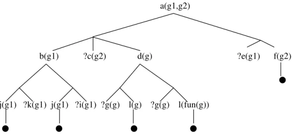
We first give an example to show how this inference procedure works. For a given query “a(g1,g2)” and a rule base below,
1. a(X,Y) ⇐ b(X) ∧ c(Y) ∧ d(g). 2. a(X,Y) ⇐ e(X) ∧ f(X).
3. b(X) ⇐ j(X) ∧ k(X). 4. b(X) ⇐ j(X) ∧ i(X).
6 SUBST(θ,α) denotes the result of applying the substitution θ to the sentence α. For example:
SUBST({x/Sam,y/Pam},Likes(x,y)) = Likes(Sam,Pam) [37].
7 headOf(r) denotes the positive atom of the definite clause r. For example headOf(“d(X) ⇐ g(X) ∧ l(X)”)
5. d(X) ⇐ g(X) ∧ l(X). 6. d(X) ⇐ g(X) ∧ l(fun(X)). 7. $askable(c(X)). 8. $askable(k(X)). 9. $askable(i(X)). 10. j(g1). 11. g(g).
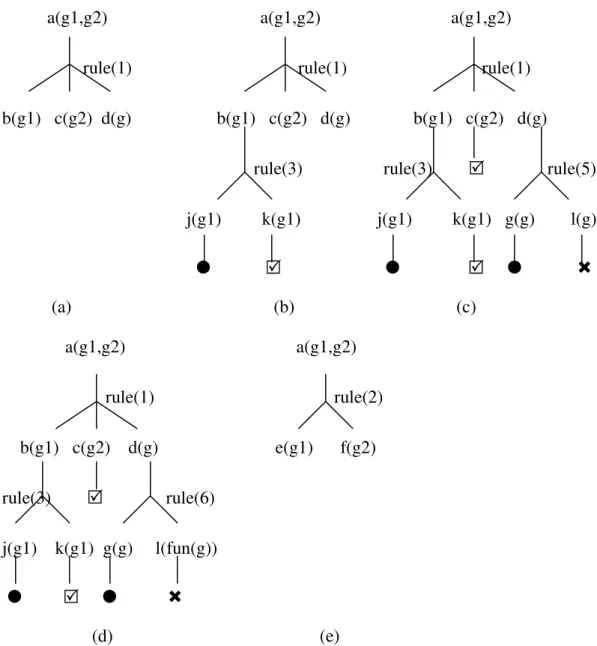
the above top-down inference procedure of jDREW will go through the following steps as shown in Figure 3-2. In Figure 3-2, the “ ” means the goal is supported by the rule base as a fact; the “ ” means the goal is not a fact in the rule base and no rule can lead to it; the “ ” means the question of an askable goal is answered “yes” by the user. We also assume that the depth-first search strategy is from left to right, the rules are scanned according to their sequence in the rule base and all the questions are answered “yes” by the user.
First, a “proofTree” data structure is initiated with a(g1,g2) as its root. The rule (1) is used as the first attempt to prove a(g1,g2). After applying unifer {X/g1, Y/g2} on rule (1), the proofTree changed to Figure 3-2(a). Consequently, rule (3) will be applied for goal “b(g1)”, which is shown in Figure 3-2 (b); rule (10) for goal “j(g1)”; $askable(k(X)) for goal “k(g1), which will cause question “?k(g1)” being asked; $askable(c(X)) for goal “c(g2), which will cause question “?c(g2)” being asked; rule(5) for goal d(g), which is shown in Figure 3-2 (c); rule(11) for goal “g(g)”; No rule can be applied for goal “l(g)”, so the inference procedure traces back one step and uses rule(6)
to apply to goal “d(g)”; rule(11) for goal “g(g)”. No rule can be applied for goal “l(fun(g))”, so the inference procedure traces back one step and uses rule(2) to apply to goal “a(g1,g2)” as shown in Figure 3-2 (e); no rule can be applied for goal “e(g1)” and no traceback operation can apply, so the goal “a(g1,g2)” fails.
a(g1,g2) a(g1,g2) a(g1,g2) rule(1) rule(1) rule(1) b(g1) c(g2) d(g) b(g1) c(g2) d(g) b(g1) c(g2) d(g) rule(3) rule(3) rule(5) j(g1) k(g1) j(g1) k(g1) g(g) l(g) (a) (b) (c) a(g1,g2) a(g1,g2) rule(1) rule(2) b(g1) c(g2) d(g) e(g1) f(g2) rule(3) rule(6) j(g1) k(g1) g(g) l(fun(g)) (d) (e)
Figure 3-2 Partial Proofs Generated By The Proof Procedure
On the other hand, we can combine all these steps together into a search tree that is composed by interleaving “or” layers and “and” layers. In “and” layer, a node is true if
any of its children is true while in “or” layer, a node is true only if all its children are true.
Figure 3-3 is a search tree of the above proof procedure. The question mark denotes that the system will ask the user when the node cannot be proved by the inference procedure.
a(g1,g2)
rule(1) rule(2) b(g1) ?c(g2) d(g) e(g1) f(g2)
rule(3) rule(4) rule(5) rule(6) j(g1) ?k(g1) j(g1) ?i(g1) g(g) l(g) g(g) l(fun(g))
Figure 3-3 The Search Tree
From Figure 3-3 we can see that goal “a(g1,g2)” will fail on rule(1) no matter what answer the user will give on question ?k(g1), ?i(g1) and ?c(g2) because there is no way to satisfy d(g).
• Optimization 1
Optimization could be done to prevent the system from asking the user any question that will not help the final resolution of the task. Based on the observation that the failure of a node in the “and” layer alone can cause the failure of its parent node, the system could check out such nodes and avoid asking any question that appeared in the subtrees that are rooted on their siblings.
• Optimization 2
In addition, the sequence of questions that are asked by the system also affects the number of questions that a user has to answer. Take the following proof tree as an example:
a(g1,g2)
?b(g1) ?c(g2) ?d(g) Figure 3-4 Example 1
Assume the user will give ?b(g1) and ?c(g2) a “yes” answer and ?d(g) a “no” answer. The user will have to answer all three questions if the questions are asked on the same sequence as they are encountered by the inference procedure. On the other hand only one question needs to be asked if ?d(g) is asked first. Even though the system has no way to know what question is more likely to be answered “no” by the user, it still can make some heuristic optimizations. By observing the position of the questions in Figure 3-3, we can find out that “no” answer on question ?c(g2) will have more impact on the total number of questions that need to be asked than “no” answers on “?k(g1)” or “?i(g1)”. The reason is that any “no” answer on a higher layer question is more likely to trim off bigger substrees than “no” answer on a lower layer question does. So, for a coarse optimization, we could simply choose the question of higher layer to begin with. Yet the above optimization only works well on a special subset of questions in which the askable nodes form a “tight group” that is defined below.
Definition 1: A set of “and” layer nodes forms a “tight group” if the first common ancestor of all the nodes is the father of at least one node of that set.
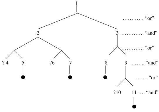
Figure 3-5 shows a more general case. In figure 3-5, each number represents a predicate of first order logic. The predicate that is preceded by a question mark means this predicate is askable. In this case, “?4” and “?6” reside on a higher level than “?10”. Yet a “no” answer to “?10” will trim off the whole search tree while “no” answer to either “?4” or “?6” can only trim off a subtree that is rooted on the or-node father of either “?4” or “?6”. So, in this case, it is better to ask “?10” first.
1 ………… “or” 2 3 …………. “and” …………. “or” ? 4 5 ?6 7 8 9 …….. “and” …….. “or” ?10 11 …. “and”
Figure 3-5 Example 1 Of a General Case
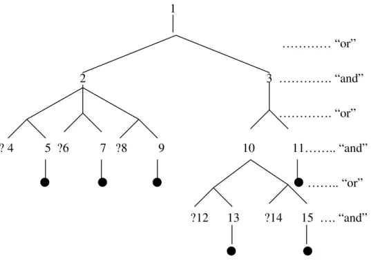
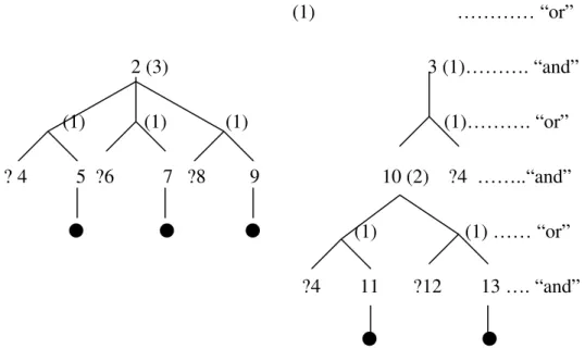
For an even more general case as shown in Figure 3-6, it is not easy to tell which question should be asked first without quantifying the impact of each question.
1 ………… “or” 2 3 …………. “and” …………. “or” ? 4 5 ?6 7 ?8 9 10 11…….. “and” …….. “or” ?12 13 ?14 15 …. “and”
Figure 3-6 Example 2 Of a General Case
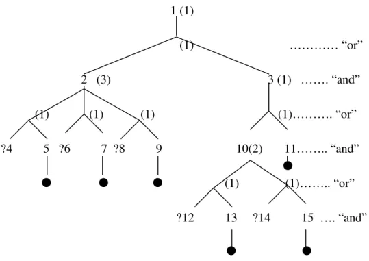
In order to quantify each question, we add a factor value to every internal node and question node of the search tree. (Note that each node on the “and” layer is a predicate and each node on the “or” layer is a rule)
The factor value of each internal node is defined as follows:
1. For each internal “and” layer node, the factor value is the sum of the factor values of its children.
2. For each “or” layer node, the factor value is 1.
1 (1) (1) ………… “or” 2 (3) 3 (1) ……. “and” (1) (1) (1) (1)………. “or” ?4 5 ?6 7 ?8 9 10(2) 11…….. “and” (1) (1)…….. “or” ?12 13 ?14 15 …. “and” Figure 3-7 The Factor Value of Figure 3-6
The impact of a question is represented by the factor value that is calculated as follows:
Assume along the path from the parent of the question node to the root of the search tree, there are n “and” layers nodes a1,a2,...an. The factor value v of the question node is:
v=
∏
= n i ai F 1 / 1 ; (1) where i aF denotes the factor value of the node ai.
According to formula (1), the factor value of “?4”, “?6” and “?8” is 1/3 and the factor value of “?12” and “?14” is 1/2.
In order to calculate the factor value of a question that appears more that once in the search tree, we introduce a variable Into denote the impact of a question on a node
n.
We define Inas follows:
1. the impact of a question on the question node of itself is 1; the impact of a question on the other leaf nodes is 0;
2. for an internal “or” layer node o,
i c n i o I I 1 max =
= where n is the number of children of o, ciis the i-th child of o.
3. for an internal “and” layer node a,
∑
= = n i a c a I F I i 1
/ where n is the number
of children of a, ciis the i-th child of a.
And the factor value of a question is equal to the impact of the question on the root of the search tree:
v= Iroot; (2) According to formula (2), the factor value of “?4” in Figure 3-8 is “1”.
(1) ………… “or” 2 (3) 3 (1)………. “and” (1) (1) (1) (1)………. “or” ? 4 5 ?6 7 ?8 9 10 (2) ?4 ……..“and” (1) (1) …… “or” ?4 11 ?12 13 …. “and” Figure 3-8 An Example Of The Factor Value
We can see that formula (1) is just a special case of formula (2).
By this, we can choose the sequence of the questions according to their factor values. That is the question of the highest factor value will be asked first.
Choosing the question set is another important aspect of this optimization. There are several strategies to choose from.
• Question selection strategy 1
We could choose a question set that includes all the questions that appear in the search tree. The whole optimization process turns out to be finding out a fastest way to trim off the search tree until the whole tree is trimmed off (the goal fails) or, on some steps during the trimming, the goal succeeds. Because the scope of the optimization is the whole tree, this choice of question set makes full use of the trimming capacity of the optimization method. So, it works best when a goal fails, yet it does not perform as well when a goal succeeds.
• Question selection strategy 2
Another proof-oriented strategy is to choose a question set that holds just enough questions for each proof. Whenever a question in the question set is answered “no”, the system will discard the remaining questions and turn to another question set. The following is an example of this approach that chooses the next question set in a depth-first, left to right sequence.
a(g1,g2)
b(g1) ?c(g2) d(g) ?e(g1) f(g2)
j(g1) ?k(g1) j(g1) ?i(g1) ?g(g) l(g) ?g(g) l(fun(g))
Figure 3-9 Search Tree Illustrating The Question Selection Strategy 2
By using the search tree of Figure 3-9, the first question set will include {?c(g2),?g(g),?k(g1)} (the questions are written in the sequence in which they would be asked). If only the answer of “?k(g1)” is “no”, the system will choose the next question set, that is {?i(g1)}. The last question set is {?e(g1)}. The idea behind this strategy is to focus on the questions that may lead to one valid proof. This seems to work more harmoniously with the goal-oriented top-down proof procedure. Yet, it has a disadvantage -- it limits the optimization locally to a small subset of questions.
![Figure 2-1 The Syntax Of The First-Order Logic [37]](https://thumb-eu.123doks.com/thumbv2/123doknet/14194488.478786/20.918.167.768.94.463/figure-syntax-order-logic.webp)