Publisher’s version / Version de l'éditeur:
Conference Proceedings Repository, 2017
READ THESE TERMS AND CONDITIONS CAREFULLY BEFORE USING THIS WEBSITE. https://nrc-publications.canada.ca/eng/copyright
Vous avez des questions? Nous pouvons vous aider. Pour communiquer directement avec un auteur, consultez la
première page de la revue dans laquelle son article a été publié afin de trouver ses coordonnées. Si vous n’arrivez pas à les repérer, communiquez avec nous à PublicationsArchive-ArchivesPublications@nrc-cnrc.gc.ca.
Questions? Contact the NRC Publications Archive team at
PublicationsArchive-ArchivesPublications@nrc-cnrc.gc.ca. If you wish to email the authors directly, please see the first page of the publication for their contact information.
NRC Publications Archive
Archives des publications du CNRC
This publication could be one of several versions: author’s original, accepted manuscript or the publisher’s version. / La version de cette publication peut être l’une des suivantes : la version prépublication de l’auteur, la version acceptée du manuscrit ou la version de l’éditeur.
For the publisher’s version, please access the DOI link below./ Pour consulter la version de l’éditeur, utilisez le lien DOI ci-dessous.
https://doi.org/10.29008/ETC2017-371
Access and use of this website and the material on it are subject to the Terms and Conditions set forth at
The effect of stiffening tabs on the performance of lobed mixers at
off-design conditions
Wright, Alexander; Mahallati, Ali; Conlon, Martin; Militzer, Julio
https://publications-cnrc.canada.ca/fra/droits
L’accès à ce site Web et l’utilisation de son contenu sont assujettis aux conditions présentées dans le site LISEZ CES CONDITIONS ATTENTIVEMENT AVANT D’UTILISER CE SITE WEB.
NRC Publications Record / Notice d'Archives des publications de CNRC: https://nrc-publications.canada.ca/eng/view/object/?id=4ec72942-6c7d-4126-8d01-831436d4d830 https://publications-cnrc.canada.ca/fra/voir/objet/?id=4ec72942-6c7d-4126-8d01-831436d4d830
Paper ID: ETC2017-371
Proceedings of the 12th European Conference on Turbomachinery Fluid Dynamics & Thermodynamics ETC12, April 3-7, 2017; Stockholm, Sweden
THE EFFECT OF STIFFENING TABS ON THE
PERFORMANCE OF LOBED MIXERS AT OFF-DESIGN
CONDITIONS
Alexander Wright
1,2, Ali Mahallati
1,3, Martin J. Conlon
1, and Julio Militzer
2 1 Gas Turbine Laboratory, National Research Council of Canada, Ottawa, ON, Canada2Department of Mechanical Engineering, Dalhousie University, Halifax, NS, Canada 3APG-Neuros, Montr´eal, QC, Canada
ABSTRACT
This paper presents a computational investigation of scaled turbofan lobed mixer stiff-ening tabs at low-speed off-design conditions. Stiffstiff-ening tabs provide rigidity to the thin lobed mixer by connecting the mixer valley to the more rigid centrebody. Evidence shows that the tabs affect the flow structures of turbofan exhaust systems at off-design core inlet swirl conditions. Observations were made downstream of the mixer in simulations that were carried out with an unstructured RANS solver and thek − ω SST turbulence model. To model off-design conditions, the core flow swirl was increased from axial flow to10◦ at
the moderate case and30◦ at the high swirl case. The tab geometry was shown to perturb
some of the less involved flow mixing structures, streamwise vortices near the lobe valley. Simulations of geometries with the tabs displayed more uniform flow throughout the com-mon nozzle with higher thrust outputs; however, these minor improvements are negated by higher total pressure losses.
NOMENCLATURE Acronyms
T KE Normalized turbulent kinetic energy, K V2 i Greek Symbols Γ circulation,R R ~ω · ~n dA ω vorticity,∇ × V ρ density Roman Symbols
CΓs streamwise circulation coefficient,
Γ ¯ uxiDh
Cωa azimuthal vorticity coefficient,pωr2+ ωθ2
Dh
¯ uxi
Cωs streamwise vorticity coefficient,ωs
Dh
¯ uxi
CP0 total pressure coefficient,
P0− ¯Psi
¯ P0i− ¯Psi
CPs static pressure coefficient,
Ps− ¯Psi
¯ P0i− ¯Psi
CT thrust coefficient
Dh equivalent diameter at the mixer core inlet
K mean turbulent kinetic energy P pressure
Re Reynolds number,ρ¯uxiDµh
u velocity component V mean velocity x axial
Y total pressure loss coefficient, P¯0i− ¯P0
¯ P0i− ¯Psi
Subscripts a azimuthal
i core flow inlet of the mixer s static, streamwise 0 total Other Symbols ¯ ( ) mass-averaged values INTRODUCTION
Medium bypass turbofan engines use a common nozzle to eject core and bypass gases to the atmosphere. Their exhaust systems typically consist of structural struts that support a lobed mixer from the centrebody, followed by the common nozzle. The hot core and cooler bypass gases interact and mix downstream of the forced mixer prior to leaving the common nozzle. Mixing the flows before ejecting them provides increased net thrust (Paynter and Birch, 1977) and reduces the jet noise (Kuchar and Chamberlin, 1980). The operating environment exposes the lobed mixer to significant thermal and mechanical stresses due to the large temperature gradient and vortex shedding from the mixer’s trailing edge. To mitigate the effects of these dynamic loads, some exhaust systems use small tabs between the centrebody and mixer to provide stiffness to the thin mixer lobes.
The mixing mechanisms produced by forced mixers are now very well understood thanks to past work (Paterson, 1984; Waitz et al., 1997; McCormick and Bennett, 1994; Yu et al., 1995; Yu and Yip, 1997). The dominant flow structures of lobed mixers are streamwise vortices— large scale structures resulting from the radial deflection of the core and bypass flows as they pass over the mixer geometry. These vortices are the largest scale flow structures and remain so as they interact with each other and other flow structures downstream of the mixer (Kuchar and Chamberlin, 1980; Kozlowski and Larkin, 1982). Mixer performance can be improved via trailing edge modification like scalloping (Kuchar and Chamberlin, 1980; Yu et al., 1997), which allows an additional pair of counter rotating vortices to develop at the trailing edge (Presz et al., 1994). The strong shear layer between the high speed core and lower speed bypass flows produces smaller scale normal vorticity along the trailing edge of the mixer due to the Kelvin-Helmholtz instability (Waitz et al., 1997; McCormick and Bennett, 1994). These two types of vorticity interact within the common nozzle producing regions of high turbulent kinetic energy (Waitz et al., 1997).
Computational fluid dynamics (CFD) has become a popular tool for examining the flows of lobed mixers because the complicated lobe geometries limit the ability of traditional probe measurement techniques. CFD provides full resolution of all velocity components through-out the measurement domain and offers a great low-cost complement to traditional higher-cost experimental techniques.
Previous studies of lobed mixers have focused on at-design conditions with very little swirl in the core flow. The present authors have investigated off-design core flow swirl conditions
and their effects on mixing and aerodynamic performance of a scaled turbofan mixer with 12 scalloped lobes (Wright et al., 2013). The present investigation aims to extend that study to in-clude mixers with stiffening tabs. A CFD-based investigation was used to examine the reaction of the tabs to off-design core swirl conditions and the subsequent effect on performance.
COMPUTATIONAL MODELLING
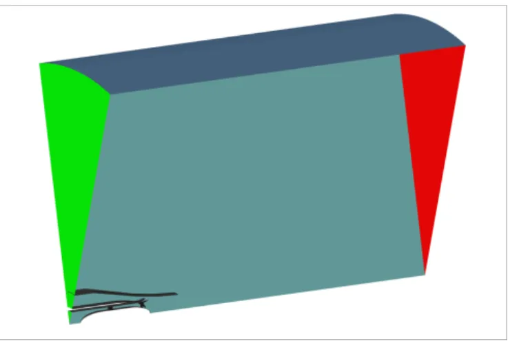
Figure 1: Computational domain and boundary con-ditions. Inlets: Green, Solid Walls: Black, Periodic: Blue, Outlet: Red.
Computational fluid dynamics offers the advantage of resolving fully three-dimensional flow fields without intru-sive probes disturbing the flow. This is especially useful in cases of sepa-ration or reverse flows, which probes may not reliably measure. This study used FINE/Open v3.2, an unstructured, density-based finite volume, Reynolds-averaged Navier-Stokes (RANS) solver developed by Numeca International. Convective fluxes were discretized us-ing Roe’s second order up-wind scheme. Diffusive fluxes were discretized using
the central differencing scheme. Turbulent closure of the Navier-Stokes equations was accom-plished with the two-equationk − ω SST model (Menter et al., 2003), which was previously shown to be the best model for simulating this sort of flow (Wright et al., 2013).
The computational domain, shown in Figure 1, encompassed one lobe period of30◦ in the
tangential direction, 20 equivalent mixer diameters,20Dh, downstream of the nozzle in the axial
direction and10 Dh in the radial direction to ensure an undisturbed far field condition.
Previ-ously measured experimental values (Wright et al., 2013) were prescribed at the boundaries. Turbulence intensities of 5% and 0.2% were applied to the core and bypass flows, respectively.
Figure 2 shows a sample of the5.5 M cell computational grid near the mixer. This number was arrived at through a mesh independence study, Table 1, and ultimately verified against experimental data, Figure 3. The unstructured grids were fine enough to properly resolve wall boundary layers, free shear layers and mixing zones.
DATA REDUCTION
Several of the parameters used to gauge the performance of the exhaust system were de-rived from the basic flow quantities of velocity and pressure fields. The primary performance parameters of interest are the total pressure loss coefficient,Y , and the thrust coefficient, CT.
The pressure loss was normalized by the dynamic pressure at a reference plane in the core and
Table 1: Mesh Independence Data.
Case No. of Cells Thrust Coefficient Nozzle Thrust 1 1, 242, 408 82.80 105.54 N 2 2, 924, 068 85.34 107.01 N 3 5, 303, 580 85.72 107.49 N 4 9, 773, 624 85.72 107.48 N
Figure 2: Sample of unstructured mesh near the mixer.
bypass upstream of the mixer,x/Dh = −1.8. The thrust was calculated as the sum of
momen-tum thrust, pressure thrust and momenmomen-tum drag. It is normalized by the sum of ideal adiabatic expansion thrust of the flow at the same upstream reference planes in the core and bypass.
Secondary parameters for understanding the mixing and flow structures are also derived from the basic flow quantities. Vorticity, a measure of the local rate of fluid element rotation, is derived from the curl of the velocity vectors; the axial component is an indicator of the streamwise vortex strength and the azimuthal vorticity,ωa =pωr2+ ωθ2, is an indicator of the
normal vortex strength. Additionally, a uniformity factor was defined,φ = X− ¯Xm
¯
Xi− ¯Xm, to provide
a quantification of mixedness for a particular flow quantity; whereX is the local point value of any scalar quantity of the flow, ¯Xm is the mass-average value at a far downstream
“mixed-out” plane or ambient condition and ¯Xi is the mass-average value at the upstream reference
plane. The mixing index,I, is defined as the mass average of the squared uniformity factor. It describes the mixedness at a plane by a single number; a fully mixed out plane has an index I = 0.
(a) Swirl,◦. (b) Total pressure coefficient, CP
0.
Figure 3: CFD predicted vs. measured pitchwise averaged core flow swirl and total pressure coefficient,CP0, measured at the reference plane,x/Dh = −1.8.
Figure 4: CFD predicted streamwise vorticity, azimuthal vorticity and total pressure coefficient fields for the design condition,0◦, with and without tabs.
RESULTS AND DISCUSSION
The numerical simulations were analyzed to determine the influence of lobed mixer stiffen-ing tabs on flow structures and overall aerodynamic performance. Three cases are presented: design, moderate and high swirl. There was no swirl in the bypass flow for all three cases. The core swirl was0◦,10◦ and30◦ for design, moderate and high conditions, respectively. All
simulations were performed at low speed conditions. Validity of the simulations is based on previous validation work for similar geometries and mesh densities published by the present authors (Wright et al., 2013).
Design Condition
Figure 5: Radial distribution of CFD predicted swirl angle at the Dx
h = 0.07 plane for 10
◦ and30◦ inlet
swirl cases. The tab was designed to have
min-imal aerodynamic impact at the de-sign condition of completely axial flow through the mixer. Figure 4 shows flow fields of the design case for the base-line geometry without the stiffening tab and the investigated geometry with the tab. The quantities shown are the stream-wise vorticity coefficient, azimuthal vor-ticity coefficient, and total pressure coef-ficient at six axial planes downstream of the mixer, Dx
h = {0.00, 0.07, 0.36, 0.72, 1.09, 1.45}. As expected, the qualitative differences
between the two geometries are small. The vortex structures take on the same size and strength, developing downstream in the same way. The only noticeable difference comes from the total
(a) 10◦, no tab. (b) 10◦, tab.
(c) 30◦, no tab. (d) 30◦, tab.
Figure 6: CFD predicted static pressure coefficient distribution on the core surface of the mixer lobe valley for10◦ and30◦ inlet swirl cases with and without tabs.
pressure coefficient contour, which indicates a slight total pressure deficit in the wake of the tab, observed in the Dx
h = 0.07 plane. In both cases, vortex structures were generated by the
radial velocity components of the core and bypass flow interacting to form a convoluted shear layer and the distinct sets of counter rotating vortex cores (Paterson, 1984). The scalloping of the lobed mixer trailing edge allowed the higher pressure core flow to expand through the scal-lop into the bypass flow prior to reaching the mixer outlet plane. The expansion of core gas is evident in planes Dx
h = 0.07 and
x
Dh = 0.36, where the expansion of higher total pressure can
be observed. The orientation of the scalloped edges, combined with the pressure difference of the core and bypass flows, resulted in a shear induced vortex observed downstream as stream-wise vorticity. The vortex along the outer edge of the scallop quickly merged with the main streamwise vortex. The vortex along the inner edge of the scallop remained distinct from the main streamwise vortex, but quickly interacted with the normal vortex and dissipated by the
x
Dh = 0.36 plane. The length scale of the scallop mixer vortex pair was much smaller than the
single pair of streamwise vortices generated by an unscalloped mixer (Wright et al., 2013). The normal vorticity began development upstream of the mixer exit plane due to the scallop and interacted with the streamwise vortices as it broke down into smaller scale turbulent structures. The normal vortex was stretched atDx
h = 0.07 and pinched off at
x
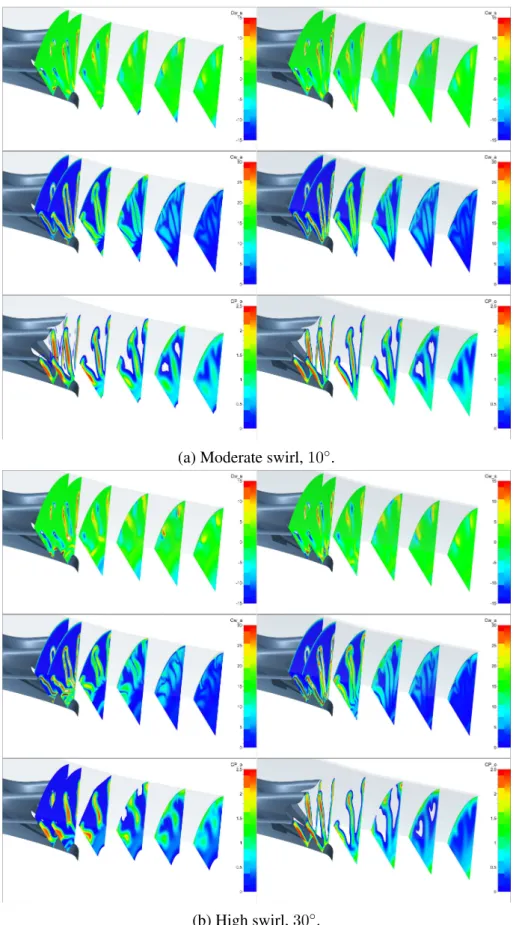
(a) Moderate swirl, 10◦.
(b) High swirl, 30◦.
Figure 7: Predicted streamwise vorticity, azimuthal vorticity and total pressure coefficient fields for the moderate,10◦, and high,30◦, swirl cases with and without tabs.
Off-Design Condition
Figure 8: CFD predicted streamwise circulation at the Dx
h = 0.07 plane.
This section will discuss the devel-opment of flow structures downstream of scallop mixers with and without stiffen-ing tabs at moderate,10◦, and high,30◦,
inlet swirl conditions. Figure 5 presents crestline swirl distribution at Dx
h = 0.07,
illustrating the effectiveness of the lobed mixer when directing the tangential com-ponent of the flow back to the axial di-rection. The swirl is largely reduced to
levels near zero for flow in the radial region of the lobe,0.28 < r
Dh < 0.72. The gap between
the centrebody and mixer allows residual swirl to persist downstream and even increase due to angular momentum conservation and the falling radius of the centrebody. Observations show that the inclusion of the tab can reduce the magnitude of the swirl in this region of flow not affected by the mixer.
The mixer does work to straighten the flow; therefore, it is helpful to examine the static pressure loading on the mixer surface. Figure 6 illustrates the loading at10◦ and30◦ swirl and
the effects the tab has on it. Moderate levels of swirl show no separation on the mixer surface. The high swirl condition does show separation in the form of a region of low static pressure with an adverse pressure gradient. It creates an analog to a wingtip vortex downstream of the mixer (Lei et al., 2012). The presence of the tab reduces the intensity of the separation near the mixer, but results in a much larger unstable separation bubble within the lobe passage.
Observing the flow structures in planes downstream of the mixer will assist the reader in understanding the flow around the mixer and the tab, when present. The development and gen-eration of the distinct streamwise vortex cores has been explained in detail previously (Wright et al., 2013; Lei et al., 2012). Some differences exist when the tabs are brought into the system, as the tab disrupts the development of the wing-tip-analog valley vortex. Instead, a passage vortex was developed as it would be in a compressor or turbine blade row. This vortex differs from the valley vortex in that it does not interact with other vortices downstream of the mixer but is instead pulled toward the centre of the jet by the static pressure deficit in the wake of the centrebody. As swirl increases, the passage vortex gains strength as evident in Figure 7.
Staying with the high swirl case, the large separation around the tab completely disrupts the mechanism that generates the scallop-derived streamwise vortex. The tab’s effect on normal
vorticity was the reduction of vortex strength along the trailing edge adjacent to the separation. It was also evident that the normal vortex did not dissipate or distort as much near the centre of the flow compared to cases without the tab. The total pressure plots, also shown in Figure 7, reveal that the high total pressure of the core flow became distorted by the residual swirl near the centre of the flow. This distortion suggests that residual swirl improved mixing near the core of the flow. The tab resulted in lower levels of total pressure throughout the mixing region, which may be attributed to the wake and associated losses of the tabs.
Figure 10: CFD predicted stream tubes and stream-wise vorticity coefficient downstream of the mixer with tabs at design, moderate and high swirl cases. Circulation, measured as the integral
of streamwise vorticity over the area of a plane of interest, is a good indicator of overall mixing and can reveal how these changes to flow structures affected the mixing performance. Clockwise circula-tion is derived from the right hand side of the lobe looking upstream and vice versa for counterclockwise. Figure 8 shows plots of circulation versus inlet swirl angle and its development down-stream of the mixer. The baseline geom-etry shows that clockwise and counter-clockwise circulation tended to diverge as the swirl angle increased. The tabs are shown to reduce the strength of cir-culation at all conditions except for de-sign. This change from the baseline sug-gests that the strength of the circulation was mainly driven by the kinetic energy of the core flow. The tab produced sep-arations in the core flow, which in turn reduced the amount of energy that could be converted into circulation for mixing. Turbulent kinetic energy values are a good indicator of where the flow struc-tures are interacting and breaking down into small scale turbulent mixing struc-tures. The turbulent kinetic energy plots in Figure 9 show where the streamwise and normal vortex interact and break each other down into smaller scale tur-bulent structures. Figure 10 illustrates the convoluted path required by fluid
ele-ments in order to pass by the tab in a case of high swirl. The design case shows little disturbance from the tab. The moderate case shows a small amount of fluid deflection. The high swirl case shows the very long and circuitous flow path around the tab, which adds to the high pressure losses.
Overall Performance
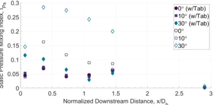
Figure 11: CFD predicted static pressure mixing in-dex,IPs, downstream of the mixer.
The mixing index of static pressure for the six cases of investigation is plot-ted versus downstream distance in Fig-ure 11. On such a plot, higher values suggest higher mixing or less uniform flow. An index of zero suggests fully uniform flow where no mixing occurs. The data confirms that the tab has very little effect on the flow at design condi-tions. The moderate condition showed reduced uniformity downstream without
the tab. The moderate condition with the tab, however, resulted in mixing index values that were similar to the design condition. The effect of the tab on mixing rates at high swirl conditions was much larger than at moderate conditions. In much the same way, the tab geometry showed mixing index levels much closer to the design condition than the baseline geometry. The highly non-uniform flow seen in the baseline geometry at moderate and high swirl conditions was due to the large low pressure zone in the wake of the centrebody. At high swirl, that wake resulted in a large recirculation zone. There was no large recirculation zone observed at any condition for the tab geometry, resulting in more uniform flow within the nozzle.
Figure 12: CFD predicted total pressure loss,Y , at nozzle exit plane,x/Dh = 1.45.
The total pressure loss measured from the reference plane upstream of the mixer to the nozzle exit, plotted in Fig-ure 12, illustrates the aerodynamic effi-ciency of the geometries. This measure-ment included all frictional losses in the boundary layers and other viscous losses due to separations and mixing. Little dif-ference was indicated at moderate swirl cases. There was high pressure loss due to the separation around the tabs at high swirl conditions. The baseline geometry
at high swirl conditions produced a very large recirculation zone in the wake of the centre-body. This zone extended to the nozzle outlet and resulted in high total pressure loss. The tabs disrupted that recirculation zone, but separation of the flow around the tab resulted in even higher total pressure loss as observed in Figure 12. The tab geometry with high swirl conditions showed the highest pressure loss of all cases investigated.
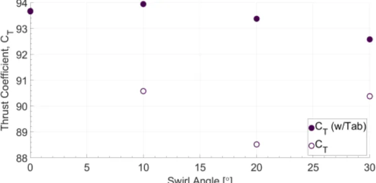
The thrust coefficient was calculated based on the flowfield at the nozzle outlet plane. Fig-ure 13 shows the thrust coefficient versus inlet swirl. It is clear that the tab geometries produced higher thrust than the baseline geometry for all cases with swirl because the flow was straight-ened by the tabs. Increased swirl with the tab geometry produced progressively worse thrust output due to the associated loss and separation of flow around the tab.
CONCLUSIONS
A numerical investigation of the flow around lobed mixer stiffening tabs at off-design con-ditions was presented in this paper. Simulations showed the tabs had negligible impact on the
flow at design conditions. However, simulations at off-design conditions revealed that the tabs affect the flow structures downstream of the mixer and the overall performance of the exhaust system.
Figure 13: CFD predicted thrust coefficient,CT.
A new streamwise vortex was ob-served in the passage between adjacent tabs at off-design conditions. The val-ley vortex did not occur because the leak-age of flow over the valley of the mixer was obstructed by the tab. In the high-est swirl case of30◦, the scallop-derived
vortex was not produced because of the very large separation bubble around the tab. The tab also stopped the large re-circulation zone from occurring
down-stream of the centrebody. The data shows that the tab improved overall flow uniformity in the exhaust for most cases. However, total pressure loss calculations indicate that the tab ge-ometry resulted in greater pressure losses than the baseline geometries. The separation around the tab made a large contribution to the total pressure loss of the exhaust system. This tab sepa-ration loss outweighed the gains of avoiding the large recirculation zone in the high swirl case. Finally, the thrust output was higher with tabs than without because the tangential component of core flow velocity was redirected axially at the expense of total pressure loss.
It must be noted that these simulations were run at low-speed laboratory conditions. It is ex-pected that the higher Reynolds number flows of engine operation conditions would exacerbate the negative effects of the tabs at off-design conditions.
ACKNOWLEDGEMENTS
This work was conducted at and paid for by the National Research Council of Canada.
REFERENCES
Kozlowski, H. and Larkin, M. (1982). Energy efficient engine exhaust mixer model technology report. Technical Report CR-165459, NASA.
Kuchar, A. and Chamberlin, R. (1980). Scale model performance test investigation of exhaust system mixers for an energy efficient engine (e3) propulsion system. AIAA Paper, 229.
Lei, Z., Mahallati, A., Cunningham, M., and Germain, P. (2012). Effects of core flow swirl on the flow characteristics of a scalloped forced mixer. Journal of Engineering for Gas Turbines and Power, 134(11).
McCormick, D. C. and Bennett, Jr, J. (1994). Vortical and turbulent structure of a lobed mixer free shear layer. AIAA Journal, 32(9):1852–1859.
Menter, F., Kuntz, M., and Langtry, R. (2003). Ten years of industrial experience with the SST turbulence model. Turbulence, Heat and Mass Transfer, 4(1):625–632.
Paterson, R. W. (1984). Turbofan mixer nozzle flow field—a benchmark experimental study. Journal of Engineering for Gas Turbines and Power, 106(3):692–698.
Paynter, G. and Birch, S. (1977). An experimental and numerical study of the 3-D mixing flows of a turbofan engine exhaust.
Presz, W. M., Reynolds, G., and McCormick, D. (1994). Thrust augmentation using mixer-ejector-diffuser systems. AIAA Paper, (94-0020).
Waitz, I., Qiu, Y., Manning, T., Fung, A., Elliot, J., Kerwin, J., Krasnodebski, J., O’Sullivan, M., Tew, D., Greitzer, E., et al. (1997). Enhanced mixing with streamwise vorticity. Progress in Aerospace Sciences, 33(5):323–351.
Wright, A., Lei, Z., Mahallati, A., Cunningham, M., and Militzer, J. (2013). Effects of scallop-ing on the mixscallop-ing mechanisms of forced mixers with highly swirlscallop-ing core flow. Journal of Engineering for Gas Turbines and Power, 135(7):071202.
Yu, S. and Yip, T. (1997). Experimental investigation of two-stream mixing flows with stream-wise and normal vorticity. International Journal of Heat and Fluid Flow, 18(2):253–261.
Yu, S., Yip, T., and Liu, C. (1997). Mixing characteristics of forced mixers with scalloped lobes. Journal of Propulsion and Power, 13(2):305–311.
Yu, S. C., Yeo, J. H., and Teh, J. K. (1995). Velocity measurements downstream of a lobed-forced mixer with different trailing-edge configurations. Journal of Propulsion and Power, 11(1):87–97.