Publisher’s version / Version de l'éditeur:
Vous avez des questions? Nous pouvons vous aider. Pour communiquer directement avec un auteur, consultez la
première page de la revue dans laquelle son article a été publié afin de trouver ses coordonnées. Si vous n’arrivez pas à les repérer, communiquez avec nous à PublicationsArchive-ArchivesPublications@nrc-cnrc.gc.ca.
Questions? Contact the NRC Publications Archive team at
PublicationsArchive-ArchivesPublications@nrc-cnrc.gc.ca. If you wish to email the authors directly, please see the first page of the publication for their contact information.
https://publications-cnrc.canada.ca/fra/droits
L’accès à ce site Web et l’utilisation de son contenu sont assujettis aux conditions présentées dans le site
LISEZ CES CONDITIONS ATTENTIVEMENT AVANT D’UTILISER CE SITE WEB.
Internal Report (National Research Council of Canada. Institute for Research in Construction), 1994-12
READ THESE TERMS AND CONDITIONS CAREFULLY BEFORE USING THIS WEBSITE.
https://nrc-publications.canada.ca/eng/copyright
NRC Publications Archive Record / Notice des Archives des publications du CNRC :
https://nrc-publications.canada.ca/eng/view/object/?id=c8e2433e-1d74-4dda-9345-6dc557053f13 https://publications-cnrc.canada.ca/fra/voir/objet/?id=c8e2433e-1d74-4dda-9345-6dc557053f13
NRC Publications Archive
Archives des publications du CNRC
For the publisher’s version, please access the DOI link below./ Pour consulter la version de l’éditeur, utilisez le lien DOI ci-dessous.
https://doi.org/10.4224/20375618
Access and use of this website and the material on it are subject to the Terms and Conditions set forth at
Temperature Measurements in Full-Scale Insulated and Non-Insulated (1x2) Gypsum Board Protected Wall Assemblies with Steel Studs
by M.A. Sultan, J.W. Maclaurin, E.M.A. Denham and R.C. Monette National Research Conseil national
Council Canada de recherches Canada
lnstltute for lnstitut de
Research ~n recherche en
Construction construct~on
Steel Studs
internal Report No.675
Date of issue: December 1994
Internal report : Institute
-- Bev Creighton ANALTSE
ion Canada ANALYZED
is an Internal report of the Institute for Research In Constructlon. Although not ded for general distrlbutlon, r t may be clted as a reference In other publlcatlons.
TEMPERATURE MEASUREMENTS IN FULL-SCALE INSULATED AND NON-INSULATED (1x2) GYPSUM BOARD PROTECTED WALL ASSEMBLIES WITH STEEL STUDS
TEMPERATURE MEASUREMENTS IN FULL-SCALE INSULATED AND NON-INSULATED (1x2) GYPSUM BOARD PROTECTED WALL ASSEMBLIES WITH STEEL STUDS
ACKNOWLEDGMENTS
This research is a Joint Research Project among the following partners. The National Research Council Canada appreciates the participation of these partners in research, both in terms of their financial contributions and in terms of their technical contributions through the Project Steering Committee.
Canada Mortgage and Housing Corporation Canadian Home Builders Association Fiberglas Canada Inc.
Roxul Inc.
Cellulose Insulation Manufacturers Association of Canada Gypsum Manufacturers of Canada
Forintek Canada Corporation
Canadian Sheet Steel Building Institute Institute for Research in Construction
TEMPERATURE MEASUREMENTS IN FULL-SCALE INSULATED AND
NON-INSULATED (1x2) GYPSUM BOARD PROTECTED WALL ASSEMBLIES
WITH STEEL STUDS ABSTRACT
This rcpon presents the temperature measurements from 5 full-scalc fire resistance tests conducted at the National Fire Laboratory on insulated and non-insulated full-scale gypsum board protected wall assemblies. Asymmetrical gypsum board installations 1x2
(one layer of 12.7 mm thick gypsum board on the exposed side and two layers of gypsum board on the unexposed side) on light steel studs were evaluated. The insulations used were glass, mineral and cellulose (wet sprayed) fibres. Tests were conducted to determine the effects of the insulation type in the wall cavity and the insulation tightness between the studs on the fire resistance rating of gypsum board wall assemblies. The temperatures measured on the gypsum board surface and on the studs are presented.
TEMPERATURE MEASUREMENTS IN FULL-SCALE INSULATED AND NON-INSULATED (1x2) GYPSUM BOARD PROTECTED WALL ASSEMBLIES WITH STEEL STUDS
1.0 INTRODUCTION
Changes included in the 1990 edition of the National Building Code of Canada (NBCC) [I] increased the sound transmission classification between dwelling units from STC 45 to STC 50. As well, changes included in the 1991 CANICSA-A82.27-M91 Standard [2] "Gypsum Board-Building Materials and Products" removed minimum density requirements for gypsum board. Either or both of these changes may have an impact on the fire resistance of both wall and floor assemblies referenced in Parts 3 and 9 of the NBCC, as well as the calculation methods in Chapter 2 of the Supplement to the NBCC.
As a result of these changes, a Joint Research Project involving the Institute for Research in Construction (IRC), the National Research Council Canada (NRCC) and 8 industry partners was conducted. The primary objective of the project was to determine the impact of the changes to the Code and Standard on the fire resistance ratings of insulated and non-insulated gypsum board wall assemblies. To evaluate these possible effects. a number of full-scale (22) and small-scale fire resistance tests (49) were conducted.
This report presents the results of 5 full-scale fire tests conducted at the National Fire Laboratory, IRC, NRCC, as part of the Joint Research Project. These tests were conducted to determine the effect of different insulations in the wall cavity and the insulation tightness between steel studs on the fire resistance performance of non-load- bearing (1x2) gypsum board wall assemblies. The temperatures measured on the gypsum board surfaces and on the studs are presented.
2.0 DESCRIPTION OF TEST ASSEMBLIES
The full-scale test assembly furnace is shown in Figure 1.
2.1 Dimensions
Five full-scale assemblies were constructed, 3048 mm high by 3658 mm wide and 128.1 mm deep. The specific dimensions for Assemblies F-07, F-09, F-10 and F-11 are given in Figures 2 to 5 respectively. Assembly F-IOB had the same dimensions as Assembly F-10.
2.2 Materials
Materials used in assemblies were as shown in the following sections. 2.2.1 Gmsum Board
Type X gypsum board conforming to the requirements of CANICSA-A82.27-M91 [2] was used. The gypsum board used in the assemblies was 12.7
mm
thick.2.2.2 Framing Materials
The steel studs used were light C sections 90
mm
wide by 30 mm deep by 0.46 mm thick, manufactured in accordance with CANICGSB-7.1-M86 [3].2.2.3 Insulation
Three types of insulation were used: glass fibre-R12 (supplied by2Fiberglas Canada Inc., Willowdale, Ontario with a mass per unit area of 1.08 kglm ), mineral fibre- R13 (supplied by Roxul Inc., Milton. Ontario with a mass per unit area of 2.78 kg/m2) and cellulose (wet sprayed) fibre (suppl$d by Thermo-Cell Insulation Ltd., Orleans, Ontario with a mass per unit area 5.25 kg/m ). All insulations used conformed to CSA Al01-M83 [41.
2.3 Fabrication
The full-scale assemblies were constructed in accordance with CANICSA-A82.31- M91 [5]. Details on assemblies are presented in Table 1. All assemblies were constructed by the same contractor using the same construction practices.
2.3.1 Steel Stud Assemblies
The steel studs were light C sections 90 mm by 30 mm by 0.46 mm and were spaced at 600 mm O.C.
In asymmetrical gypsum board (1x2) wall assemblies with studs spaced at 600 mm
O.C., the exposed side had one gypsum board layer and the unexposed side had two gypsum board layers: base and face layers. All gypsum board was applied vertically to the studs. The base layer on the unexposed side was attached to steel studs with Type S drywall screws, 25 mm long, spaced at 600 mm O.C. in the field of the gypsum board and at 300 mm O.C. along the edges of the board. The face layer was attached to both the base layer and steel studs with Type S drywall screws, 41 mm long, spaced at 300 mm
O.C. along the edges of the gypsum board and in the field of the board. The gypsum board layer on the exposed side was attached to steel studs with Type S drywall screws, 25 mm long, spaced at 300 mm O.C. along the edges of the gypsum board and in the field of the board. Screw locations and gypsum board joints are shown in Figures 6 to 8 [5]. Screw heads on both the exposed and unexposed faces were covered with joint
compound. Gypsum board joints were also taped and covered with joint compound. 2.3.2 Insulation
Mineral fibre batts were supplied in different sizes: one sample was 90 mm thick by 615 mm wide and 1220 mm long and the other was 90 mm thick by 584 mm wide and 1220 mm long. Glass fibre batts were supplied in samples 90 mm thick by 615 mm wide and 1220 mm long. The cellulose fibre insulation was sprayed wet on the single gypsum board layer side after the installation of the thermocouples.
2.4 Instrumentation
Type K (20 gauge) chromel-alumel thermocouples, with a thichess of 0.91
mm,
were used for measuring temperatures at a number of iocations throughout an assembly. Inside the cavities, the thermocouples were attached to 6 wire hangers installed midwav between the studs and at mid-depih of the studs at distances of 114and 314 of the height of the wall. By providing tension to the hanger wire, the thermocouples were positioned flush with the surface of the gypsum board. Thermocouple locations for each assembly are shown in Figures 2 to 5.
The deflection at the unexposed surface was measured at the centre of the wall as shown in Figure 9 using the electro-mechanical method described in Reference [6].
3.0 TEST APPARATUS
The tests were carried out by exposing the assemblies to heat in a propane-fired vertical fumace as shown in Figure 1. The furnace was lined with fire brick covered with a 25.4
mm
thick ceramic fibre blanket. The assemblies were sealed at the edges against the furnace with ceramic fibre insulation. The fumace temperature was measured by nine (20 gauge) shielded thermocouples in accordance with CANNLC-S101-M89 171. The average of the nine thermocouple temperatures was used to control the furnacetemperature.
4.0 TEST CONDITIONS AND PROCEDURES
4.1 Fire Exposure
The ambient temperature at the start of each test was approximately 22OC. During the test, the wall assembly was exposed to heating on the exposed side, in such a way that the average temperature in the fumace followed as closely as possible the CANAJLC- S 10 1 [7] standard temperature-time curve.
4.2 Failure Criteria
The failure criteria for the tests were from CANNLC-S 101-M89 [7]. An
assembly was considered to have failed if a single point thermocouple temperature reading on the unexposed face rose 180°C above the ambient temperature or the average
temperature of the 9 thermocouple readings under the insulated pads on the unexposed face (see Figure 10) rose 140°C above the ambient temperature or there was passage of flame or gases hot enough to ignite cotton waste.
4.3 Recording of Results
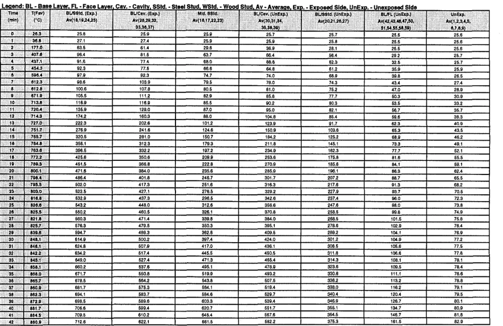
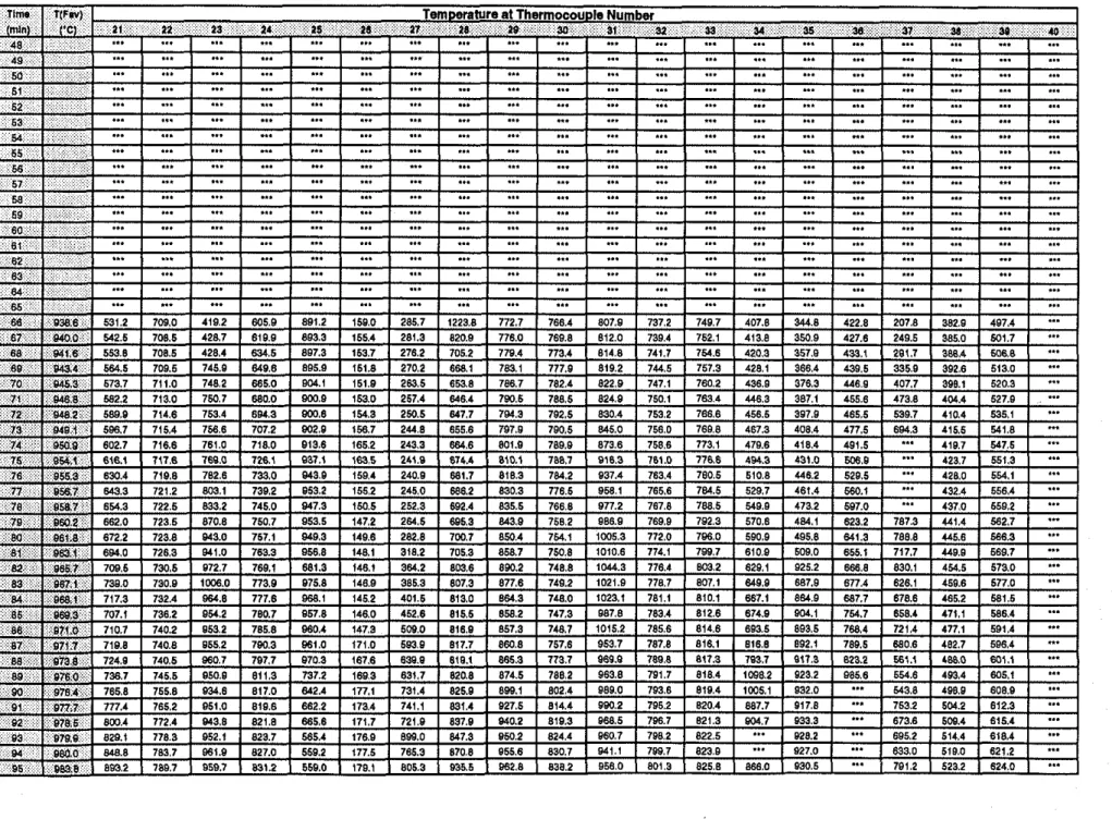
The furnace and wall assembly temperatures were recorded at 1 minute intervals. In Test F-IOB, due to a power failure at 65 min, all computer-stored data up to that time was lost.
5.0 RESULTS AND DISCUSSION
The results of the 5 full-scale fire resistance tests are summarized in Table 1 in which the failure times are given for each assembly.
Tabular data for each test is presented in the following:
Test F-07 F-09 F-10 F- I OB F-11 Single Location Temperature Tables 2 4 6 8 10 Average Surface Temperature Tables 3 5 7 9 11 Deflection Measurement Tables
***
12 13 14 15The average temperatures on gypsum board surfaces and on the studs are plotted in Figures 1 1 to 15. Detailed temperatures for all nine thermocouples under the insulation pads on the unexposed surface are also plotted in the Figures.
The deflections measured at the unexposed surface are plotted in Figure 16.
5.1 Effects of Different Insulations in (1x2) Non-load-bearing Assemblies
(Figure 17)
Glass Fibre Insulation - Tests F-09 (insulated) and F-07 (non-insulated) were carried out to invcnieate the cffect of thc installation of nlass fibre insulation (GFI) in a wall caviw on the fire rGistance ratings of (1x2) asymmetrical installation of gyp'sumboard wall
assemblies. The temperature failure criterion was reached at 65 min for Test F-09 and at 65 min for Test F-07. These results suggest that, in (1x2) assemblies, the 90 mm thick glass fibre insulation in the wall cavity did not affect the fire resistance rating.
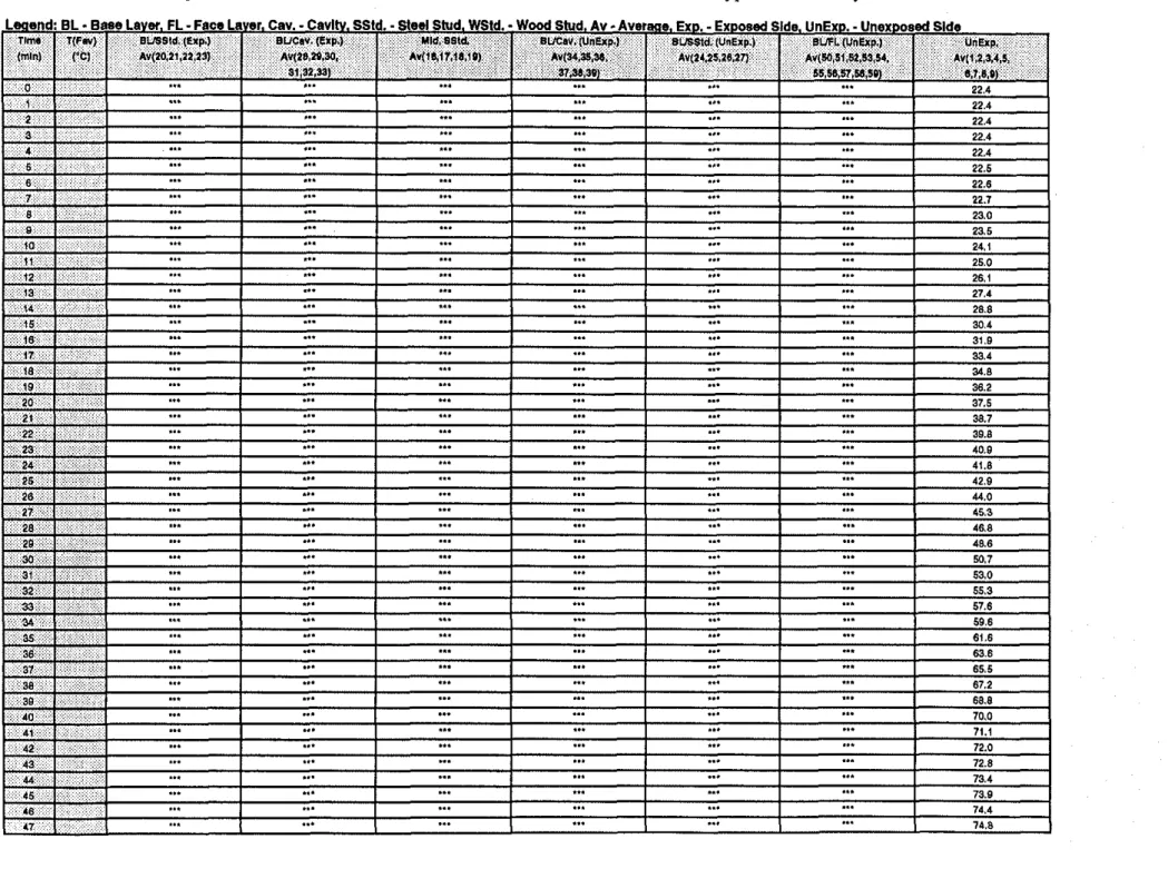
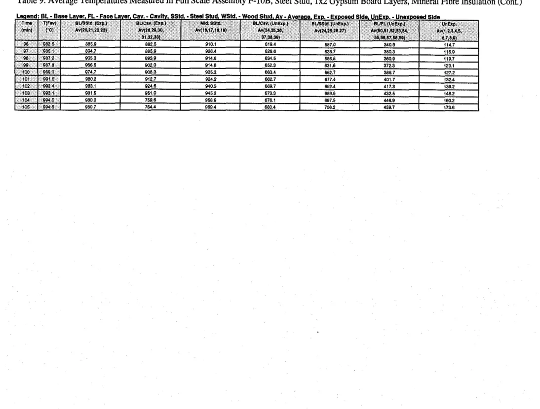
Mineral Fibre Insulation -Tests F- IOB (insulated) and F-07 (non-insulated) were
conducted to investigate the effect of installation of mineral fibre insulation (MFI) in a wall cavity on the fire resktance ratings of asymmetrical (1x2) gypsum board wall assemblies. The temperature failure criterion was reached at 100 min for Test F-1OB and at 65 min for Test F-07. These results suggest that, in asymmetrical (1x2) assemblies, the installation of 90 mm thick mineral fibre in the wall cavity provided a 54% increase in the fire resistance rating compared to a non-insulated assembly.
Tests F-10 (MFI, 584 mm wide, installed loose) and F-IOB (MFI. 615 rnm wide, installed tight) were conducted to determine whether the width of the insulation batts between the studs has an effect on the fire resistance performance of (1x2) gypsum board wall assemblies. The temperature failure criterion, as shown in Figure 18, was reached at 60 min for Test F-10 and at 100 min for Test F-IOB. To maximize the benefit of the insulation on the fire resistance rating in (1x2) assemblies, it is important to have insulation tightly installed between the studs.
Cellulose Fibre Insulation -Tests F-1 1 and F-07 were conducted to investigate the effect of wet sprayed cellulose fibre insulation (CFI) in the wall cavity on the fire resistance ratings of (1x2) asymmetrical installation gypsum board wall assemblies. The temperature failure criterion was reached at 62 min for Test F-l 1 and at 65 min for Test F-07. In (1x2) assemblies with 90 mm thick wet sprayed cellulose fibre insulation in the wall cavity, the cellulose fibre insulation slightly decreased the fire resistance rating compared to a non-insulated assembly.
6.0 CONCLUSIONS
1. In non-loaded 1x2 gypsum board wall assemblies, the glass fibre insulation did not affect the fire resistance performance of the assemblies while the cellulose fibre insulation slightly decreased the fire resistance by 5% and mineral fibre insulation increased the fire resistance performance by 54% compared to non-insulated assemblies.
2. To maximize the benefit of the insulation on the fire resistance performance, it is important to have insulation tightly installed between the studs.
5
7.0 REFERENCES
1. National Building Code of Canada (Part 9), National Research Council Canada, Ottawa, Ontario. Canada, 1990.
2. CANICSA-A82.27-M91, Gypsum Board-Building Materials and Products, Canadian Standards Association, Rexdale, Ontario, 1991.
3. CANICGSB-7.1-M86, Cold Formed Steel Framing Components, Canadian General Standards Board, Ottawa, Ontario, Canada, 1986.
4. CSA-A101-M83, Thermal Insulation, Canadian Standards Association, Rexdale, Ontario, 1983.
5.
CANICSA-A82.3 I-M91, Gypsum Board Application, Canadian Standards Association, Rexdale, Ontario, 1991.6. Lie, T.T. and Bemdt, J.E., Remote Measurement of Large Deflections in Fire Tests, Division of Building Research, National Research Council Canada, Building Research
Nnte
.
.- - -
Nn - .-
. R 4 - . > 19727. CANNLC-SlO 1 -M89, Standard Method of Fire Endurance Tests of Building Construction and Materials, Underwriters' Laboratories of Canada, Scarborough, Ontario. 1989
Table 1. Full-Scale Assembly Parameters and Fire Test Results
X
-
Gypsum Board Type X GFI -Glass Fibre InsulationMFI
-
Mineral Fibre Insulation 584 rnrn wlde MFI'-
Mineral Fibre insulation 615 rnrn wldeCFI'
-
Cellulosic Fibre insulation 615 rnrn wide (sprayed)-, . . ,. ... E;? . . F::L . . . ... . - .
,
. . . . . . . .,
: . . . . .,
. . .:. . . . . . .,
.,
. . . . ,,
. . . .,
: . . . . : .;
*
,& . ; : . . . ' ; . , . , , , . . ..,
. . .,:
.:.,
. . . : . . . . ':-~ . . .,
~ : ~ ~ ~ ~ % ~ ~ H $ ~ ~ : : ~ ~ ~ ~ ~ ~ ~ ~ ~ . ~ ~ ~ ~ ~ 2 ..: . , ; . . . ::. 'i .. . . . :12
.
..:..
).: . . . ;l . . :::: : ...;
: . - - - - . F T v - - - " n g ... : :i . : . ; :. ... .- : . . .:: . . . . : . :*
. . . : :.. . . .*
. : ,% . :: :;::
~ ? ? * ~ ~ ~ ~ ~... . ~... ~ ~ ~ ~ ~ ~ ~ r - o . . - ~ ~ . ~ ~ : ~ . ~ : . ~ . ~ . . ~ . ~ ~ . ~ ~ ~ % ~ ~ ~ s ~ ~ ~ 14.7q . . . ::: ... 'E; : : ;,*
. :.. .:. i :::.
.:: . . . ...:...:... :(i.:;> :::. u. . : r.. . . . .?. y. . : . . ::: .N.:y .N ... : . : . . : ... !8. : .:.p. :& ;. ylq:r. .% ..."
. . . . ... z z g s :.:: .? .--:
. . . 0, : ..: . . .&& .: :: ".. .>.'.>"
... ::. ... .? ::. ... .:. .^" . . . ;.. .< .::: :.: ..& <*.ul . . . Z,:? : . ~ . . . ... :.:: .- . . . . ;-
: . . . :. . . . . . . I . . . . .: :.o
? ':.' . . ,- .,
:g s ~ 5 . e : d a . . z s n i ~ s . : ' : . . . ;& ... .: .:.. . > : : .: ... . ...
::, & ::: ..*
. . . I. & ::.8'22 I E'B v I 0'18 1 1'29 I 2'88 I sea1 I E'WI : . . :, ::: @ i.,.
V22 O'SV E'28 v l 9 1'68 SEO1 0'9% : ~ ' t ) o . i . .:: 4 : ::
2'22 I E'Z* I V8L I vss I P'LB I s'sa I 8 . ~ 6 I .. . ~ ~ ~ q . , . : : l ::::: n. :..::
w,, -.I" ,.", 7 , " w7a moo I. :..=* . ... .n.. ,.
0'22 I 9.E I 9'8L I 9'6s I B'5Q 1 6'9s 1 C26 ( ' y $ v , ' : : . { : : ::+ .::;.
1'22 0'E 1'18 I I'EE 8'8L E.16 9'56 : . ' e . w ~ : ~ . . .,r'::' n.7, I we7 I w*, L.71 I J'", I
"',
,
I ,'O, I . , . I . . : . r . : :. ", - - " I " ~~-
.
. . . : . . . . . . Z P 0-
4 0 E 8=
,- rn 05
111 E i...
m w . . .3,
. . .
c c . : . , . . . 8 m . ~ ' . . '3.
. ~ ~ : . . . . : : : : : : : 4 m ~ 4 d u i d d d i i i ~ r d d C - j i i ; ; I i i i I i I ~ ~ ; ; ~ ~ ~ - ? e ~ ' ~ ' ~ ~ r Y -. ~ -. . . . . ' : .~ : . . . . . ... . . ... .... ... ... ... . . . . ... .... ... . . . . ... ... ... . . . ~. * I E ' .aa
: $ ; . $ . ;.
F c : . : . . . :::.. .:. ::.: :.:~.. :.': .:.. :..:: .:. $:; . :... 5: ... ... ... . . . . ... ... . . . . . . . . .~-
. . .-
. . . . . . ~'E;;=
. . . . .;6:
I : : : : : ; ; ; ; ; : . . . . ~~~~-
,;:*
5.
.;; , ::: . . . . . . . . . . . c F p ... . . & . . . ~ . . . . ~ ~~~~~-~ m m m ? Y - . . . . ~ . . $ ~ . . F k l . O n w O w . r . , e b b , - ,"".?.. G ; ; ~ ; s ; c b e , c e...
: h C C C C n$er.?ZI c b c c c 3 " " . :..~. ~ . . . . . . .~.. . . .
.
. . . . . . . . . .- . . . .% . . .. . .
.
c c :: .~ . : . . . ~ ' . ' . . . 5 . ? : . . . . . ".. . .. . . . . . . : : :.
. . .
. . . . . . . . . . . . . : : : . . : . . . . .. . ~ . . . 9 ' . . m m . m . . m .8
. . . ... . . . .. . .
. . . . . . . + n . m Y . w * . 9 ' D Y N * . 0 m h . f ' D * - - P O - - - . . . " 4 ! ~ ~ . - : . ~ . ~ 1 ' P ; m q * * , ~ m q ? S . . . . . . . . . $ 8 . . . . 5 . . . . . . . . . . . . . ..
. . .
. . . ..~.. . . . . . . . . . . ~ i i i I I i i I ; I I i I i i I i ~ ~ ~ ~ ~ ~ ~ ~ ~ ~ ~ ~ ~ ~ ~ ~ ~ ~ ~ ~ ~ ~ ~ ? ~ ~ * ? * -~ ; I I ; i i i ; i i i I i i ; I I ; -~ -~ -~ -~ -~ ? Y ? ? 9 P ? " -~ ? ? ? Y 7 ? ? ? -~ ? " ? ? ' Y " I i I ; I i I I ; i i I I I I ; i i ~ ~ ~ ~ ~ ~ " ~ " 4 ~ Z ~ ~ ~ " ~ " s ? " n c " " " " Y ~ f i i ; I i I I I I I I i I ; I ; I I ~ ~ $ " ~ ~ " 9 ? " ' ~ " ' ? o ? " " c o l q q q ? F ~ 9 7 I ; i i ; I i I i i i ; I I I I I ? - S - ? " 9 ? ? ' " Y ? 3 C ? ' 9 " 9 ? ? ~ r o m ? " ? ~ = ; ; I I ; ; ; ; ; ; ; ; i ; ; $ ; ; ; ; ; ; ~ ; ; $ ; 5 ; ; ~ ; ; ; $ ~ ; ; 2 2 ; ; ; ; $ + ; ; i 1 ; 1 ; ; i ; ; ; ; i 1 1 1 ; ; s ~ r ~ z z ; ; 7 ~ & z ; f z " - c m ' e x ? ? ? ~ ~ " * , ; ; ; ; ; ; ; ~ I ; ; ; I I I I I O ? " ? ~ ' D ? ? ? ' ~ W ~ - ~ - ~ ~ ? ? ~ ? ~ ~ ? ~ ? ? ~ ~ ~ o ~ ~ ; $ & i i ; ; l i ; i ; i i l i O ~ ~ 9 O q ~ ~ ~ m ~ m 9 ~ C F < ? - N ? ? ~ ~ Y ? 9 Y ? Yw t i t i t i t i i : ; : : ; ; ; i ; i : : ; z ; ~ ~ z ~ ~ 9 ~ 9 ? - ? ~ ? ~ t z ~ z ~ z z ~ ? ~ ~ ~ " ?
~ ~ : x g g 3 S . : ~ : : : : : : : I i i ~ ~ ? F 9 " - - - ~ ' ? ' ~ ~ ~ ~ Q ~ ? ~ c ? 9 9 " 9 Y ~ 9 : i i i ; $ a $ ; z a 9 ? - " 9 ~ ? ~ q ? ~ ? - o - - ? 9 ' " ? 9 " ~ ~ ? : . ; i I i ; I i I ; ; ~ Y ? ~ ' " ? - ' 9 ' " ' D " ? " 4 ? ~ ~ ? ? " h ~ ~ ? ' " " n 0 m . . . . . .3.3
~ n n d a g g g g 8 8 X 8 S g S g 8 . .~. . . . . r c d 2 ? ? ? ? 1 ? ~ ~ " ~ g g g g ~ ~ = = " l " f ~ 8 8 S 8 8 8 8 P P Z Z I f 0 " ' $. . .
. a " . . . ' .
. . . . . - w ~ n : p ~ $ g = p ~ g x ~ $ 8 8 & ~ ~ $ 6 8 ; 6 ~ 6 ~ g g g ~ P P ~ rr :X . . . f P ~ P ~ ~ ~ ~ . . ~ a ~ . ~ , s , ~ ~ ~ ~ ~ ~ $ ~ ~ $ - m ~ - ~ - ~ ~ ~ I ; . . ~ . .~ . . : . . . . . . . . . ~ :. ~ :S . . . . . . . . . . . . . . . . . . $ ...:... ~ : ~ r - . - . - . * F " : ? ~ g $ : ~ ; 9 , % $ $ 2 % $ :;. i i : : : : : : . . : : : ~ ~ $ ~ ~ ~ ~ ~ 9 9 7 ? ~ ~ 9 ~ a ~ ? ~ ? 9 ~ ~ 7 ? ~ ~ ? ~ -or-; IP .~.. ~ I . . . . . . . . .:.
. . . a . I.
~. .
: . . . . . . .,~, . . . .~. ... ; ; ; ; i I i I I I ; i ~ ~ ~ ~ ~ ~ z ~ ~ q ~ ~ - ~ ~ - ~ ~ o l ~ ~ ~ ? ? ~ ~ ~ ~ ~ ? m m w m m o 6 1 X % 6 8 S S d W : : : i : : : : : ~ : : ~ ~ ~ ~ ~ ~ 9 0 9 ? N ? Y ? ~ ? f f f ? ~ C f f f f f f ~ ~ ... " ' 6 . 6 . 6 - m m e ~ c-1
. . . . . . 6 i d g :~ ~ . . . . . . . . . &,p:.~.. ... 8 S S 9 s s s s s s 8 8 s 8 8 8 8 8 8 8 8 s 8 % ~ g ~ H $ ga a a a a 3 E J 1 ~ ~ 1 ~ 3 ~ l 5 0 3 3 3 ~ 2 3 ~ 2 3 2 2 ?
c c c c , , ~ ~ k k k e ~ ~ ~ ~ ~ ~ ~ ~ ~ ~ g g ~ g ~ ~ g Z ; ; ~ ~ ~ f ; a ; a ~ z $ ~ - . 9 ~ ~ 9 - ~ ? ? ? ? ? ? ? 0 ? ~g g : ~ ~ - n ~ z s ~ P p P ~ g $ g p ~ ~ ~ t E ; " - : " -
~ - . " g . ~ z . $ z 3 , - . 8 " , 8 g - -8
. . .m m m 8 8 8 f ~ f f ~ f P 8 % 8 ~ ~ 8 ~ 2 5 8 3 % % $ ~ ~ %
g $ $ $ o g : g g ~ ; $ ~ g $ ~ g g g g g 3 g g g ~ g $ ~ ~ - r * r r * + w w r * r * * + r r w $ $ a $ $ E X % S 8 Z z m ~ c ~ c c c c , , ~ , S s s ~ ~ % 3 3 3 $ 3 s 8 X S % ~ ~ C c c c ~ c c c , c c , , , ~ ~ ~ ~ ~ 8 ~ % % ~ 6 E ~ ~ ~ 8 8 S 8 g % 3 E k & 3 g E e l t $ 2 E D Z Z 8 3 8 % 3 8 - - - - ~ ~ ~ - ~ ~ X O O ~ - P P P , - - -~ ~ n - g z z z p s g s p ~ s g P P P g p f ~ f p : ~ ~ g
m m m m m m m Z 5 8 8 8 8 X X % % m m m m m m 3 ~ ~ ~ ~ z z ~ ? ? l o n o ~ z o o z e e s ~ $ - - - b c - m m m , 8 ~ 2 ~ ~ ~ ~ ~ ~ s 8 8 i % k $ ~ ~ z z $ ~ $ c b c c c 8 S Z z z 3 8 8 % % 3 k 3 X X 8 % % k ~ ~ ~ $ $ ?.*,
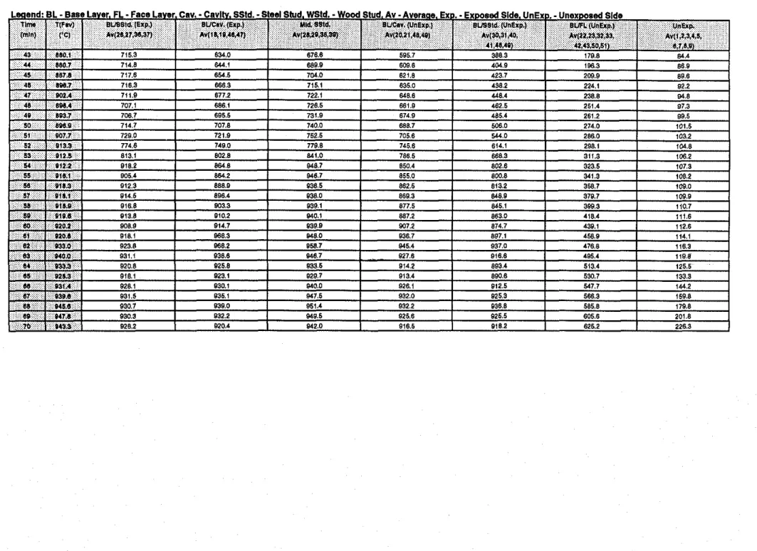
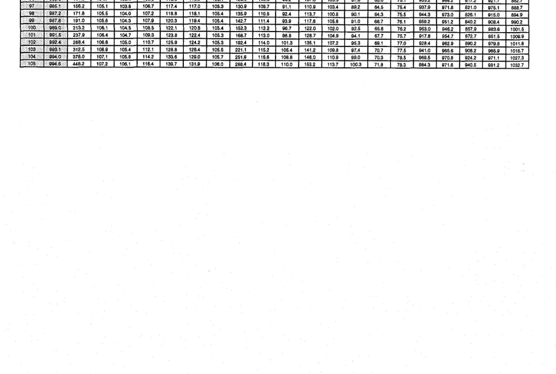
. . . ? Y q ? q . ? q . q c q ? . , C q " r - r : q q q N " Y 9 9 9Table 9. Average Temperatures Measured in Full Scale Assembly F-lOB, Steel Stud, 1x2 Gypsum Board Layers, Mineral Fibre Insulation
: .* , .: , ,: . ,, . :
.. . . .
...
I...
I...
I...
I.,.
I...
1 22.4a : : 1 ' . : : 1
...
...
...
...
.,.
...
22.4L 51 I
,.,
I...
I...
I...
I...
I...
epls peswxeun
-
'axaun ' 0 ~ 1 s pesodx3-
'ax3 ' e w m v-
AV 'pnls PWM-
'PJSM 'PIUS POIS-
'PJSS ' a c e 3-
'nu3 'JeAal ooej-
14 'leAU1 esaa-
l a :pueml 13.1 1udl1 18'o~r.o t'*'n I ) ~ V 'draw BV Iuwl -81 ~P'W'U'OP'SO 'K'CE'KS'IS'OG~~V I'munlims (16 sz's0zhv l ' d ~ 3 ~ n l ' ~ ~ a lwl'~e '%'n'rcl*v I'dxpun)'~~ms 1 8 1 ~ 0 ~ ~ ~ 1 ~ ~ l ~ v pi88 'PIW Iec'6c'~s 'Ww szhv I'dal) A W ~ B ICC'LK'ltD~hV Wr3) PISMETable 11. Average Temperatures Measured
in
Full Scale Assembly F-11, Steel Stud, 1x2 Gypsum Layers, Cellulosic Fibre Insulation (wet spray)Leaend: BL
-
Base Laver. FL-
Face Laver. Cav.-
Cavltv. SStd.-
Steel Stud. WSM. -Wood Stud. Av.
Averme. E ~ D .-
Exoosed Slde. UnExo.-
Unexoosed Sidennu TIFW) BV881d IExp.) suclv. (Exp.) Uld. Sold. BUwr. (UnElp.) BV98ld. [UnErp.) BLFL(lJnup) UnElp. (mlnl I'C) AV(lA10.2435] IWVPL29.32. AvlI~.l7,22,23) A~(30.3l.M. ~ 1 2 4 2 t . 2 6 , ~ ~ Av(U,U.1447.W. 1 ~ i t , ~ , a 6 5 .
33.3Y,3?) 3538.30) 41,%86,ULO)
Table 12. Centre Deflections Measured in Full-Scale Assembly F-09, Unloaded Assembly
Table 13. Centre Deflections Measured in Full-Scale Assembly F-10, Unloaded Assembly
Table 14. Centre Deflections Measured in Full-Scale Assembly F-lOB, Unloaded Assembly
Fire Exposed Side - A Unexposed Side
r
5 Studs Q 600.0 rnm O.C.1
18 24 zn3!.
se E E 9 00 w 0 19 37 U 51 -3657.6 rnrn D&g Not To S m * SectionA-A
I
E E 9 N (D i-t
Fire Exposed Side
r-
AUnexposed Side
Dmring Not To Smlo
1-
5 Studs Q 600.0 mm O.C.1
Section A-AI
r
E E2
-t 0 *)I
Figure 3. Thermocouple Locations in Full-Scale Test S-09
' 28
qq.
IS.. 29 3 1 1 43 ' 10%
i e 21 24 " s7. w. a,. s 51:
n ?p 38 38. su 37 JO. s " IFire Exposed Side Unexposed Side 5 Studs O 600.0 rnrn O.C.
1
B
a
g
U za 52 3n 34. $ 8 . .?
1 8 2 5a=!
E E 99
0 21?:
::
Y JO.
1 V 19Z7 51=?
-3657.6 rnrn D*np Not To Smls Section A-AFire Exposed Side
r A
d
90.0 rnrnt
Unexposed Side Section A-Ar
5 Studs 8 600.0 rnrn O.C.1
Figure 5. Thermocouple Locations in Full-Scale Test S-1 1
r
EE
2
*
0 r)I
-3657.6 rnrn ' ?a,.
l, .? 29 31. 17.. U, :
24 a!!'
n 2d 3B. sa 37 30. w; '
18 19 21 47 " 37. 3,. 50 s3 30. 2Snp 51 ; ;:
Fire Exposed Side
Unexposed Side
I--
5 Studs 8 600.0 mrn O.C.. . . .
.
. . .
I
*. .
I. .
.
.
.
.
. .
I II
. .
I
-9k 'I.
.
0 EI
.
.
I
. .
I
E E EI
I
I
0 9 .I. .
J. .
.I rn 0 00 -I -0I
I
I
8, I I.
.
1
1
I I I 01
1
. .
'I
V) I I I. .
I I IJ
. .
I I. . . .
.
. .
. . .
.
4 6 0 0 m m C - 4 6 0 0 m m L-LL
3657.6 mm-1
Figure 6. Screw Locations For Steel Stud, 1x2 Gypsum Board Layers,
Fire Exposed Side
d
90.0 rnrnf
Unexposed Sider
5 Studs CP 600.0 rnrn O.C..
. . .
.
. .
. .
1
- . .
.
.
I I. .
I
. .
I
.
.
I. .
1
I 10 rnrn. .
. .
I.
.
1 0 0 0. .
I
E.
.
I
. .
EE
E 9. .
I.
.
I
I.
.
5:
m n*
0I
I
@, II
. .
..
IE
I
. .
I
0
m V) I I 0 wI
.
.
I I. .
50 rnrnlI
I.
. .
.
. . .
.
. .
. . . .
e - 4 6 o o r n r n L- l a o o m m C ]
r n - I - = -3657.6 rnrn M n g Not To SscrbFigure 7. Screw Locations For Steel Stud, 1x2 Gypsum Board Layers,
Fire Exposed Side 90.0 rnrn
f
Unexposed Side 5 Studs 8 600.0 rnrn O.C.. . . .
.
. .
1
.
. .
. .
. .
. .
. .
I 10 rnrn I+,
-k. .
E 'II
. .
I
. .
E EI
I
I
E 0 9 .I. .
-1. .
.I n 0 03+
0I
I
I
8 I I. .
I m1
'I
Z 1 I IE
1
1
.
.
'I
V) I I.
.
I IJ
. .
I.
. .
.
-
. .
. .
. .
-4600rnmL
4 6 0 0 rnrnC 6 .rnrn1
-DmriIq Not To smbFigure 8. Screw Locations For Steel Stud,
1x2
Gypsum Board Layers,Fire Exposed Side
Unexposed Side
@ Attatchment Point For Measurement of Deflection During Test
Gypsum Board Joint Stud 4
r
'
I
f
'
Figure 9. Deflection Attatchment Point For Full-Scale Tests
1
E E*
N V )-
E E 9 m*
0 5 Studs 8 600.0 rnm @ O.C.A
k
3657.6 rnm2
1
Ikmmp Not To sea*
I
I
II
II
1I
II
II
IL I
I
II
II
II
I II
II
II
II
6
I
II
I
II
II
II
I II
II
II
II
II
I II
II
II
I IB
5 2 E l *. .
10 13 IS 17 -El E E7
E3
&
11.
h
18.
&I w 0 N 4 s"
;2 14.
IS 19 El 8 El I. 1219.2 mm 3251.2 mrn Dmrlng Not To Sm*E
l
Thermocouple Under Std. ULC St01 Insulated Pod Bare ThermocoupleFigure 10. Thermocouple Locations on Unexposed Surface
Average Values ULC Furnace Temp.
BUSStd. (Un-.) Failure Criterion 1 (Rm. Temp. + 139'C) 0 10 20 30 40 50 60 70 80 90 100 Time (min.) 0 0 10 20 30 40 50 60 70 80 90 100 Time (rnin.)
(b) Unexposed Temperature Distribution
- - -Thermocouple 2 Thermocouple 6 .---- Thermocouple 3 --- Thermocouple 7 - Thermccouple4
-
- -
Thermocouple 9 Failure Criterion 2 (Rm. Temp.+
1 BO'C)1000
-
(a) Average Face Temperature Distribution Average Values-
ULC Furnace Temp.
-
BUCav. (UnExp.) --- BUFL (UnExp.) Failure Criterion 1
-
(Rm. Temp.+
139'C)-
0 10 20 30 40 50 60 70 80 90 100 Time (min.) 1000 Unexposed Face(b) Unexposed Temperature Distribution - Thermocouple I -.-.-.---Thermocouple 5
800 - - - Thermccouple 2 Thermocouple 6
p
--- Thermoaxlple 3 --- Thermocouple 7-
-
Thermocouple 4 -Thermocouple 8 600- -
Thermocouple 9 3 Cs
a
E
400r-"
200 Failure Criterion 2 (Rm. Temp.+
180'C) 0 0 10 20 30 40 50 60 70 80 90 100 Time(min.)
ULC Furnace Temp. .. BUCav. (UnExp.) BUSStd. (UnExp.) Failure Criterion 1 (Rm. Temp.
+
139'C)Time (min.)
1
000
(b) Unexposed Temperature Distribution - Thermocouple 1 .--.-.-Thermocouple 5
800
- --Thermocouple 2 Thermocouple 6 .---- Thermocouple 3 --- Thermocouple 7 w - Thermocouple 4 -Thermocouple 8600
-
-Thermocouple 9 3izi
z
400
r-"
200
Failure Criterion 2 (Rm. Temp.+
180'C)0
Time (min.)
Time (min.)
1000-
0 800-
600 C 1000(b) UnexposedTemperature Distribution - Thermocouple 1 Thermocouple 5
800 - - - Thermocouple 2 Thenocouple E
---
Thermocouple 3 Thermocouple 7-
-
Thermocouple 4-
Thenocouple E 600- -
Thermocouple 9 33
a
4008'
200 Failure Criterion 2 (Rm. Temp. + 1 EVC) 0 1 ' " 1 " ' 1 " ' 1 " ' 1 " ' 1 " ' 1 " ' 1 " ' 1 ' " 1 " ' ~ " ' 1 ' " 1 " ' ~ " ' ~-
-
(a) Average Face Temperature Distribution Average Values-
-
ULC Furnace Temp.
-
-
-
--- BUCav. (Em.)-
-
-
BUCav. (UnExp.)-
-
BUSStd. (UnExp.)-
--- BUFL (UnExp.)Time (min.)
Figure
14.Temperature Distributions For Full Scale Test Assembly F-1OB
400
e
200
n-
-
./"
Failure Criterion 1 --
(Rm. Temp.+
139%)-
-
1-- I-
/ : ~ ~ " ' " ~ * " ~ ~ " ~ " ' " " ~ " ' ~ " ' ~ " ' ~ " ' ~ " ' ~ " ' ~ " ' ~ ' ~ ' ~ " '-
-
1000
-
(a) Average Face Temperature Distribution Average Values-
-
ULC Furnace Temp. --
- - BUSStd. (Exp.) - BUCav. (Exp.) Mid. SStd. BUCav. (UnExp.)-
BUSStd. (UnExp.)-
-
--- BUFL (UnExp.)-
UnExq. Failure Criterion I - (Rm. Temp. + 139'C)-
' m l v o ~ I ~ s . l ~ o n 0 10 20 30 40 50 60 70 80 90 100 110 120Time (min.)
1000(b) Unexposed Temperature Distribution - Thermocouple 1 .---.-..-Themacouple 5
800 - --Thermocouple 2 Thermocouple 6
p
.---- Thermoxuple 3 --- Thermocouple 7-
- Thermocouple 4-
The-uple 8 600-
-Thermocouple 9 =I-
$
400I-"
200 Failure Criterion 2 (Rm. Temp. + 180'C) 0 0 10 20 30 40 50 60 70 80 90 100 110 120Time (min.)
(a) Deflection Measurements For Unloaded Full-Scale Assembly F-09
5
9
Time (min.)
(b) Deflection Measurements For Unloaded Full-Scale Assembly F-10
5
0
Time (min.)
(c) Deflection Measurements For Unloaded Full-Scale Assembly F-1OB
5 1 " ' 1 " ' 1 " ' 1 " ' 1 " '
-
Mid Stud Deflection, Stud 4-
-
-
-10 I # , , I . , , 1 , , . ~ . , . I , , 0 20 40 60 80 100 120 Time (min.)Figure
16.Measured Deflections For Full-Scale Assemblies (Cont.)
(d) Deflection Measurements For Unloaded Full-Scale Assembly F-11
5 E
s
C 0.-
3
F -5 n -1 0 I-
I I I-
O L
-
Mid Stud Deflection, Stud 4-
-
-
-
-
I I I 0 I 20 40 60 80 Time (min.)Full-Scale (1x2, 12.7 mm, Type X Gypsum Board)
65
min
65min
62min
No Insulation GFI MFI CFI
F-07 F-09 F-1 OB F-1 1
GFI
-
Glass Fibre lnsulationMFI
-
Mineral Fibre lnsulationCFI
-
Cellulosic Fibre Insulation (wet spray)Figure 17. Fire Resistance Ratings of Insulated and
Non-Insulated
(1x2)Gypsum Board Wall
Assemblies
FUN-Scale (1x2,12.7
rnrn
Thick Type X Gypsum Board)c
I
60min
100min
Loose Fit MFI
. F-10
Tight Fit MFI
F-1OB
MFI