Vincent P. Manno and Michael W. Golay Energy Laboratory Report No. MIT-EL-83-009
by
Vincent P. Manno and
Michael W. Golay
Energy Laboratory and
Department of Nuclear Eng-ineering Massachusetts Institute of Technology
Cambridge, MA 02139
MIT-EL-83-009
October 1983
Sponsored by: Boston Edison Co. Duke Power Co.
Northeast Utilities Service Corp.
ABSTRACT
ANALYTICAL MODELLING OF HYDROGEN TRANSPORT IN REACTOR CONTAINMENTS
by
Vincent P. Manno and Michael W. Golay
A versatile computational model of hydrogen transport in nuclear plant containment buildings is developed. The background and significance of hydrogen-related nuclear safety issues are discussed. A computer program is con-structed that embodies the analytical models. The thermo-fluid dynamic formulation spans a wide applicability range from rapid two-phase blowdown transients to slow incompres-sible hydrogen injection. Detailed ancillary models of molecular and turbulent diffusion, mixture transport pro-perties, multi-phase multicomponent thermodynamics and heat sink modelling are addressed. The nume'rical solution of the continuum equations emphasizes both accuracy and effic-iency in the employment of relatively coarse discretization and long time steps. Reducing undesirable numerical diffu-sion is addressed. Problem geometry options include lumped parameter zones, one dimensional meshes, two dimensional Cartesian or axisymmetric coordinate systems and three dimensional Cartesian or cylindrical regions. An efficient lumped nodal model is included for simulation of events in which spatial resolution is not significant.
Several validation calculations are reported. Demon-stration problems include the successful reproduction of analytical or known solutions, simulation of large scale experiments and analyses of "thought experiments" which test the physical reasonableness of the predictions. In particular, simulation of hydrogen transport tests per-formed at the Battelle Frankfurt Institute and Hanford Engineering Development Laboratory show good agreement with measured hydrogen concentration, temperature and flow fields. The results also indicate that potential areas of improvement are enhanced computational efficiency, further reduction of numerical diffusion and development of con-tainment spray models. Overall, a useful tool applicable to many nuclear safety problems is described.
ACKNOWLEDGEMENTS
This research was conducted under the sponsorship of Boston Edison Co., Duke Power Co., Northeast Utilities Service Corp. and Public Service Electric and Gas Co. of New Jersey. The authors gratefully acknowledge this
support. The first author also received partial support from the U.S. Department of Energy. The authors thank all those who assisted them during this research especially Dr. Kang Y. Huh, Dr. Lothar Wolf, Mr. B.K. Riggs, Ms. Cindy Sheeks, Ms. Rachel Morton and Prof. Andrei Schor. The work was expertly typed by Mr. Ted Brand and-Ms. Eva Hakala.
TABLE OF CONTENTS Page ABSTRACT 2 ACKNOWLEDGEMENTS 3 TABLE OF CONTENTS 4 LIST OF FIGURES 7 LIST OF TABLES 10 NOMENCLATURE 11 1.0 Introduction 14 1.1 Problem Description 14 1.2 Historical Background 16 1.3 Scope of Work 21 2.0 Literature Review 23
2.1 Hydrogen Related Problems in Nuclear
Plants 23
2.2 Relevant Computational Methods 31
2.3 Containment Analysis Tools 36
3.0 Analytical Modelling 41
3.1 Overview 41
3.2 Modification of the BEACON Program 44
3.2.1 Continuum Regions 44
3.2.2 Lumped Parameter Zones 51 3.2.2.1 Inclusion of H2 in
Existing Formulation 51 3.2.2.2 Model Improvement 52 3.2.3 Ancillary Model Development 59
3.2.3.1 Thermodynamic and
Transport Properties 59 3.2.3.2 Condensate Films and
Heat Transfer 60
3.2.4 Inherent Limitations of the
Modified Code 63
3.3 Longer Term Transient Modelling--MITHYD 64 3.3.1 Basic Equation Formulation 66
3.3.2 Turbulence Effects 73
3.3.3 Mass Diffusion 78
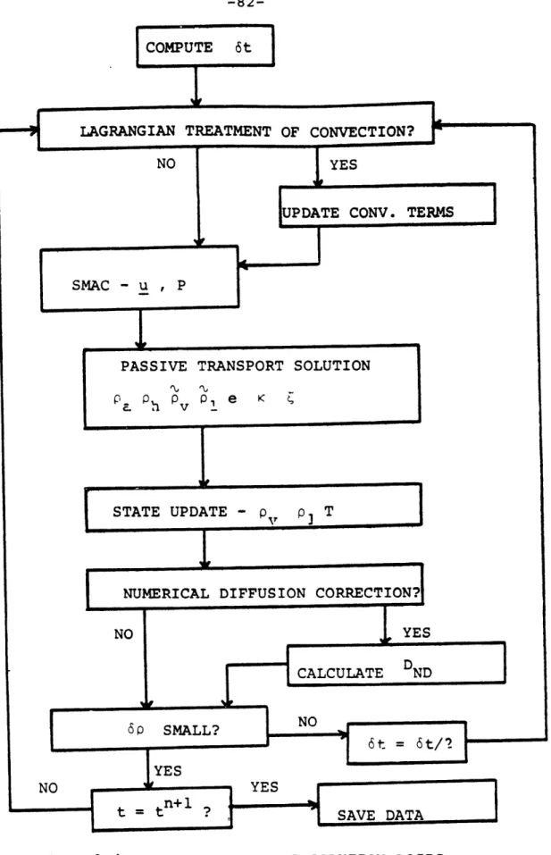
3.3.4 Solution Scheme 81
3.3.4.1 Treatment of Convection
and Numerical Diffusion 84 3.3.4.2 Flow and Pressure Fields 87 3.3.4.3 Transport Equations 98 3.3.4.4 Information Update and
State Determination 108 3.3.4.5 Initial and Boundary
Page 3.3.4.6 Incompressibility Check 118 3.3.5 Physical and Computational Inter- 119
facing of MITHYD and Overall Code
4.0 Results and Discussion 122
4.1 Validation Methodology 122
4.2 Results Using the Modified BEACON 124 Equation Set
4.2.1 Air and Water Blowdown 125 4.2.2 Hydrogen and Water Blowdown 129 4.2.3 Analysis of Slower Transients 133 4.2.4 Transition to Slower Mixing Model 138
4.3 Longer Mixing Transients 139
4.3.1 Battelle Frankfurt Tests 143 4.3.1.1 Facility and Testing 143
Program Review
4.3.1.2 Simulations Based on 158 Selected Tests
4.3.2 Hanford Engineering Development 209 Laboratory Tests
4.3.2.1 Facility and Testing 209 Progran Review
4.3.2.2 Simulations Based on 214 Selected Tests
4.4 Lumped Parameter Model Results 248
4.5 Discussion of Results 252
4.6 Model Capabilities vs Other Approaches 255 4.7 Computational Effort Analysis 258 5.0 Conclusions and Recommendations 261
5.1 Conclusions 261
5.2 Recommendations for Future Work 264
6.0 References 267
APPENDIX A: COMPUTER APPLICATION TOPICS 275
A.1 General Principles 275
4.2 Acquisition, Installation and Modification 276 A.3 Brief Review of Modifications 281
4.4 Segmented Loading 283
A.5 Production Mode Execution 289
A.6 Application on a Non-CDC System 290 APPENDIX B: INPUT DECKS FOR REPORTED SIMULATIONS 292 APPENDIX C: ANALYTICAL ASPECTS OF POSSIBLE EXTENSION 304
TO CHEMICALLY REACTIVE FLOWS
C.1 Introduction 304
C.2 Important Phenomena 304
Page
C.2.2 Deflagration Regime 306
C.2.3 Detonations 309
C.3 Flow Modelling 312
C.3.1 Flows Near a Stationary Flame 312
C.3.2 Reactive Flows 314
C.4 Outline of a Composite Model 319
C.5 Conclusions 322
C.6 References 324
APPENDIX D: IMPORTANT CONSIDERATIONS FOR 326 ASSESSING AN IMPLICIT SLOW MIXING
SOLUTION SCHEME
APPENDIX E: ADDITIONAL REMARKS ON THE SOLUTION OF 335 THE SLOW MIXING MODEL ENERGY EQUATION
LIST OF FIGURES
Figure Title Page
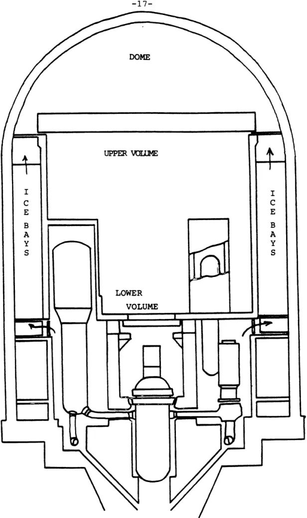
1.1 PWR Ice Condenser Containment 17
1.2 Hydrogen Concentration vs Metal Water 19 Reaction
2.1 Flammability and Combustion Limits of 27 Air-Water-Hydrogen Mixtures
2.2 Effect of Steam on Hydrogen Combustion 30 3.1 Basic BEACON Time Advancement Logic 49
3.2 Coordinate System Definition 50
3.3 Molecular Mass Diffusivities 80
3.4 MITHYD Solution Logic 82
3.5 Thermodynamic Property Functional Fits 115
4.1 Blowdown Problem Geometry 126
4.2 Gas Phase Flow Field at 0.1 Second 127 4.3 Void Fraction Transients at Selected 128
Locations
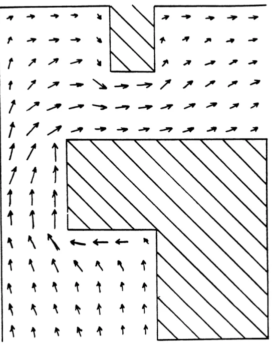
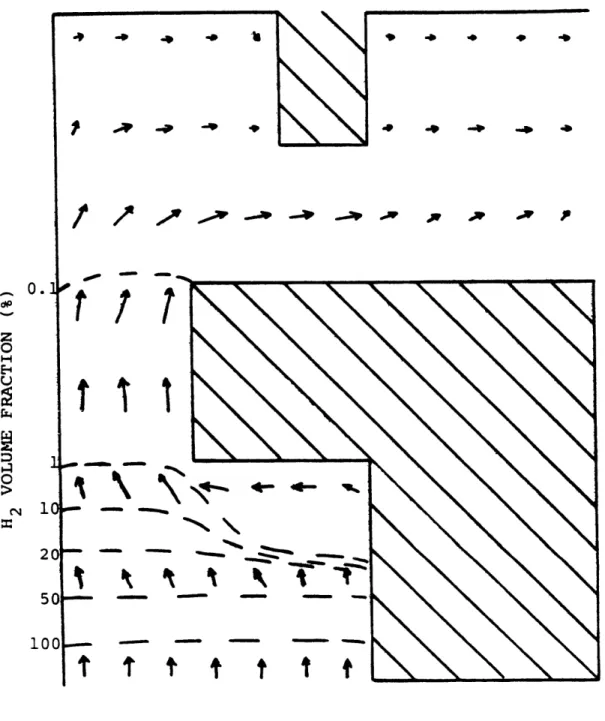
4.4 Gaseous Flow Field and Hydrogen Distri- 130 bution Map at 0.10 Second
4.5 Gaseous Flow Field and Hydrogen Distri- 131 bution Map at 0.20 Second
4.6 Hydrogen Volume Percent vs Time 132 4.7 Problem Geometry Used In BEACON Analysis 136
of BF2-Type Transients
4.8 Computational Switching Problem Specifi- 140 cation and Convergence Behavior
4.9 Evolution of Hydrogen and Velocity Fields 141 4.10 Flow Field and Hydrogen Concentration at 142
1 and 10 Seconds
4.11 Schematic Diagram of Battelle Frankfurt 145 Facility
4.12 Perspective View of BF Facility 146 4.13 Possible Compartmental Connections and 147
Dimensions
4.14 Typical BF Instrumentation Locations and 149 Source Injection Schematic
4.15 Hydrogen Sensor Electrical Schematic 150 4.16 32 Node Coarse Mesh Model of BF2 and BF6 161
4.17-4.19 Hydrogen Volume Fraction and Velocity 163-Profiles at 20, 100 and 200 Seconds of 165 BF2 Simulation
4.20 Development of Velocity Field in BF2 167 Simulation
4.21 Hydrogen Concentr.tion Transients at 168 Five Selected Locations During BF2
Page 4.22 Hydrogen Volume Fraction and Velocity 170
Profile at 100 Seconds of Open-BF2 Simulation
4.23 Development of the Velocity Field in 171 Open-BF2 Simulation
4.24 Hydrogen Concentration Transients at Five 173 Selected Locations During Open-BF2 Simulation
4.25 Time Dependent Behavior of Turbulence 175 Parameters
4.26 Hydrogen Volume Fraction and Velocity 176 Profile at 100 Seconds of Closed-BF2
Simulation
4.27-
178-4.29 Hydrogen Volume Fraction and Velocity 180 Profiles at 20, 100 and 200 Seconds of BF6
Simulation
4.30 Hydrogen Concentration Transients During 182 First 200 Seconds of BF6 Simulation
4.31 Development of the Velocity Field During 183 First 200 Seconds of BF6 Simulation
4.32 Mixture Density Time Response During 184 First 200 Seconds of 8F6 Simulation
4.33-4.34 Hydrogen VolumeFraction and Velocity 186-Profiles at 2000 and 4000 Seconds of BF6 187 Simulation
4.35 Comparison of Predicted and Measured 188 Hydrogen Concentrations for BF6
4.36 Local Temperature Behavior During BF6 189 Simulation
4.37 Mixture Density Behavior During BF6 190 Simulation
4.38 Vertical Orifice Velocities vs Time 192 4.39 Estimated Numerical Diffusion Coefficients 194
at 1000 Seconds of BF6 Simulation
4.40 50 Node Model for BF6 Simulation 196 4.41 Velocity Profile and Time History During 197
50 Node BF6 Simulation
4.42-4.44 Hydrogen Volume Fraction Profile During 199-50 Node BF6 Simulation at 1000, 3000 201 and 5000 Seconds
4.45-4.47 Temperature Profile During 50 Node BF6 202-Simulation at 1000, 3000 and 5000 Seconds 204 4.48 Comparison of Measured and Predicted 205
Hydrogen Concentrations During 50 Node BF6 Simulation
4.49 Development History of Velocity Field 207 During 50 Node BF6 Simulation
Page 4.50 Comparison of Orifice Region Froude Numbers 208
of the Two BF6 Simulations
4.51-
210-4.52 HEDL Facility Schematics 211
4.53 HEDL Lumped Parameter Analysis 218 4.54 Discrete Model of HEDL Facility 219
4.55-
221-4.58 Flow and Temperature Fields at 50 and 300 225 Seconds into HEDL B Simulation
4.59 Hydrogen Concentrations During HEDL B 226 Simulation vs Data
4.60 Normalized Velocity Component Behavior 228 During HEDL 8 Simulation
4.61 96 Node Model of HEDL Facility 240
4.62-4.65 Flow and Temperature Fields in Jet and Non- 241-Jet Regions at 50 and 350 Seconds into 244 96 Node HEDL B Simulation
4.66 Hydrogen Volume Fraction Predictions vs 246 Data During 96 Node HEDL B Simulation
4.67 Behavior of Normalized Velocity Components 247 During 96 Node HEDL B Simulation
4.68 Six Room Lumped Problem 249
4.69 H2 Transient of Six Room Problem 251 A.1 Basic Computer Application Plan of Operation 279 A.2 Slow Mixing Code Solution Structure Logic 285
LIST OF TABLES
Table Title Page
2.1 Deflagration-Detonation Transition Data 29 3.1 Comparison of Transport Property Approxi- 61
mations vs Data
3.2 Turbulence Model Constants 76
3.3 Illustrative Example of Iterative State 114 Definition Logic
4.1 Long Term Problem Specification Attempted 134 Using Modified BEACON Equation Set
4.2 Synopsis of Attempts at Simulating BF2 137 Using the BEACON Equation Set
4.3 Phase I Battelle Frankfurt Tests 151 4.4 Phase II Battelle Frankfurt Tests 156 4.5 BF2 Testing/Simulation Overview 159 4.6 Over-relaxation Factor Sensitivity Study 172 4.7 Transient Froude Number in Orifice 191
Region During BF6 Simulation
4.8 HEDL Hydrogen Mixing Test Matrix 213
4.9 HEDLB Blower Specification 217
4.10 Lumped Parameter Predictions vs Analysis 250 Results
4.11 Comparison of Hydrogen Analysis Tools 256
4.12 Computer Resource Utilization 259
A.1 Environmental Library Routines Retained 280 for Use With Modified Code
A.2 Modification Summary 282
A.3 Plotting Subroutines Deleted From the 284 Modified Codes Execution Procedures
C.1 Important Hydrogen-Air-Water Reaction 310 Steps and Nssociated Rate Expressions
NOMENCLATURE
Some of the variables defined below have more than one meaning. All possible meanings are presented. The correct interpretation is either obvious or stated in the context of the symbol's use. There are a few symbols used
in the text which do not appear in this listing. These are used once in a very specific context and are defined at that time.
The following dimensional conventions are utilized: L-lenqth, M-mass, T - temoerature, t-time, VD-variable dimension and 0-D-dimensionless. Three listings are
presented - symbols, subscripts and superscripts. SYMBOLS
A - area (L2 ) or coefficient (0-D) 8 - coefficient (0-0~
C - specific heat (L /t2T), coefficient (0-D) or constant (VI)
c - mass fraction (0-D) or sound speed (L/t)
D - diffusion constant (L2/t) or coefficient (0-D) E - coefficient (0-0)
e - specific internal' energy (L2 /t2 )
F - degree of implicitness (0-D) or coefficient (0-D) f - force (ML/t 2 )
G - coefficient (0-D)
q - gravitational acceleyat on (L/t2 )
h - specific enthaloy (L /t ) or heat transfer coefficient (M/L tT)
I - junction inertia (1/L)
J - mass ohase change rate (M/L t) K - loss coefficient (VD)
k - thermal conductivity (ML/t T) or TKE (L2 /t 2 ) LHS - left hand side
m - mass flow rate (M/t) p- pressure (M/Lt )
Q - volume flow rate ( /t) R - gas constant (L /t T) r - radial dimension (L) S - source strength (VD) Sc - Schmidt number (0-D) SM - mass source strnq 2th (M/t) U - total energy (ML /t )
u - r direction velocity component (L/t) or velocity (L/t)
V - volume (L )
v - axial velocity comoonent (L/t) W - junction mass flow rate (M/t) w - 6 direction velocity (L/t)
x - dimension (L) or quality (0-D) z - axial dimension (L)
a - void fraction (0-D) or velocity coefficient (L/t) 8 - geometry flag 0O-D) or velocity coefficient (L/t)
r - diffusivity (L /t)
y - velocity coefficient (L/t)
6 - change (VD) or velocity coefficient (L/t)
E - small number (VD) or velocity coefficient (L/t) 6 - third dimension (L or O-D) or angle (radians) K - turbulent kinetic energy (L /t )
X - third dimension option flag (0-D) - viscosity (M/Lt) 2
v - kinematic viscosity (L /t)
- dissipation of turbulent kinetic energy (L2 /t3 ) p - mass density (M/L )
a - shear stress tensor or velocity coefficient (L/t) T - wall shear stress (M/Lt2 )
- normalized phase change rate (1/t) Y - transported entity (VD) < > - ensemble average (VD) SUBSCRIPTS a - air c - condensation D - draq E - energy e - evanoration f - friction fg - vaporization q - gas or gravity gl to g3 - qaseous components h - enthalpy or hydrogen
i - radial or lumped zone index j - axial or junction index k - 6 cell index L - lumped reqion 1 - liquid M - momentum m - mean o - blower inlet r - radial s - steam w - water - vector SUPERSCRIPTS M or m - molecular n - time step index r - radial
T - turbulent z - axial
6 - third direction
- turbulent and molecular - fluctuation or perturbation - aooroximate value
o - old value
1.0 Introduction
1.1 Problem Definition
The potential problems associated with the inadvertent or accidental introduction of combustible gases into nuclear power plant containment buildings have been recognized for many years. Of all the potential
constituents, hydrogen gas is of the greatest concern in light water reactor (LWR) safety due to the abundance and potency of its sources in a typical LWR plant. The
three orincipal sources are: production as a byoroduct of an exothermic fuel cladding-steam chemical reaction,
radiolytic decomposition of water and corrosion of certain metallic species present in the containment. Prior to the Three Mile Island (TMI) accident in March
1979 most nuclear safety analysts believed hydrogen concerns were adequately addressed in the commercial licensing process.
The TMI event and especially the hydrogen
ignition which occurred has fostered renewed attention in this area. One important lesson learned is that large amounts of hydrogen can be produced and released to the containment over a wide range of time frames. Further,
the potential detrimental consequences of this evolution are strongly determined by the pre-chemical reaction behavior of the various effluent species. In response to this problem, the requlatory authorities have proposed and in some cases required, the installation of various
prevention and/or mitigation schemes including deliberate ignition and ignition prevention systems. In many
instances remedies are formulated without the benefit of sufficient analytical support to aid in the assessment of efficacy or desirability.
When one considers the progression of hydrogen behavior in nuclear containments, five general phenomena are identified. The first is hydrogen source definition since its characteristics define both the relevant time frames and bounding compositional end states. The second phenomenological regime involves the pre-chemical
reaction flow transient which determines the combustion potential through the specification of local fluid-thermodynamic conditions. As hydrogen concentrations
increase, ignition criteria and proqression become important. Dependina uoon the local conditions and strength of the ignition source, either a subsonic deflaqration wave (flame) or a detonation wave (shock) will result.
The purpose of this work is to develop
analytical methods to treat the pre-chemical reaction thermo-fluid dynamic transient. The analytical
methodology is applicable to rapid or slow transients. As models are described their assumptions and limitations are specified. Further, this work unifies these models
into a single tool (comouter program) for the convenient analysis of a wide range of problems.
Prior to proceeding to the body of this work, a general introductory remark is in order. The overall
thrust of this endeavor is to develop a realistic
approach to an actual nuclear safety problem. The general lesson that should be ascertained from the TMI experience is that nuclear safety analysis must become more
concerned with events that will probably occur over the course of a plant's operating life and less fixated on scenarios of events which have only the smallest
possibility of occurrence. Also, the analytical approach must be based on the goal of producing best estimate results with well understood uncertainty bounds. This is
indeed in line with the good engineering practice of applying conservatisms after a realistic analysis is performed. In the consideration of complex systems with
strong interactions, the orescriptive definition of "conservative" analyses as embodied in the current
nuclear requlatory apparatus is intrinsically flawed and worthy of change.
1.2 Historical Background
The inadvertent combustion of volatile elements is a common safety concern in many industrial
facilities. In nuclear plant applications these concerns arise during normal operation and unexoected events. The unexpected occurrences are of the greatest significance. Figure 1.1 deoicts a particular containment design and is
provided as a physical reference for the problem. The hydrogen damage ootential increases precisely when the proper operation of critical safety systems needs to be assured. Equipment damaqe can result from the impact of detonation waves originating at explosions or from
exposure to elevated temperatures or flames.
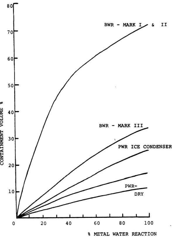
The most significant hydrogen source is its production as a chemical byproduct of the exothermic
zircaloy fuel cladding - high temperature steam reaction which can occur during undercooling events. The reaction has an approximate threshold temperature of 1600°K. The potency of this source is graphically depicted in Figure
1.2. The imoortance of this figure is noted when one realizes that the nominal flammability limit of hydrogen
in air is 4% by volume. In order to "control" this source, the regulatory requirements state that peak cladding temperatures cannot exceed 1480°K and total
zircaloy metal reacted cannot exceed 1% of the core
inventory during a credible accident. The conformance to this standard is demonstrated throuqh the use of
conservative licensing analysis in conjunction with prescribed assumptions as to the performance of man and machines during the postulated events. By using this
approach this source is "eliminated".
Radiolytic decomposition of water occurs in both the reactor coolait system (RCS) and containment sump after a postulated loss of coolant. This source
BWR - MARK & II 70 60 50 40 30 20 10 0 20 40 60 80 100
% METAL WATER REACTION
FIGURE 1.2:CONTAINMENT HYDROGEN CONCENTRATION VS METAL WATER REACTION
dominated pre-TMI licensing considerations since it could not be eliminated physically or analytically. While the total amount of hydrogen potentially produced by this source is large, its production rate is relatively low
(order of many hours). Hence concentration control can be accomplished through the use of various removal devices such as catalytic recombiners. Hydrogen production due to
the corrosion of metallic elements is accelerated in the warm and humid post-accident environment. Two elements of greatest concern are aluminum and zinc (which appears principally in paints and protective coatings). Control of this source is accomplished by strict material
accountinq procedures.
The TMI accident demonstrated the shortcomings of this overall approach in that the significance of the metal-water reaction hydrogen potential has been
underestimated. While hydrogen produced in the reactor and trapped in the coolant svstem (eg. the infamous "hydroqen bubble" of the TMI accident) has little
reaction potential due to the depressed oxygen level in the system, once it is vented from the RCS the
containment can easily support an ignition. This indeed occurred at TMI as evidenced by a pressure spike in the containment pressure measurements, depressed containment oxygen content and subsequent visual evidence of
The regulatory reaction to these concerns has focused on the installation of new prevention/mitigation systems. Included amonq these are inerting strategies
(which decrease oxygen concentration but also causes operational concerns when human access is required) and controlled ignition devices which deliberately burn hvdroqen at lean, non-detonable, concentrations. In addition, the use of flame suooressants (eq. HALON gas),
controlled containment venting (which aggravates radiological releases), water-foqginq systems and catalytic absorption systems have been proposed. The basic concern which motivates the present research is that implementation is leading analytical support which calls into question the efficacy or even the desirability of any one or combination of these aforementioned
alternatives. 1.3 Scope of Work
There are many ohenomena related to this work worthy of study. The scope of this work encompasses the develooment and testing of analytical methods which
accurately predict pre-chemical reaction flow. The hydrogen source strength and introduction mode are assumed to be defined a priori to these analyses. The division of pre- and oost-reaction reqimes is a logical one since the important physical phenomena as well as the porcess time scales of each regime are qualitatively
chemical reactions.)
The dynamic domain of interest spans rapid two-phase blowdown transients which are descriptive of jet or relief valve releases to slower near-homogeneous flows which are exemplary of slowly degrading cores or radiolytic sources. The treatment of longer term
scenarios are more central to this work since they
encompass most of the potential occurrences addressed by the proposed regulatory remedies. The major physical asoects of the problem are: two-ohase effects, buoyancy, turbulence, diffusion, heat transfer and condensate
behavior. The computational schemes must be both
physically and economically appropriate to the problem. An example of physical appropriateness is the proper treatment of diffusion which can be a dominant transport mechanism in a low flow regime. Economical
appropriateness relates the computational exoense of solving a problem versus the quantity and quality of the
information accrued from such an analysis.
Given the stated work scooe and acknowledging this to be the initial product of a larqer research
effort, the particular qoal of this work is to develop a basic tool which identifies and treats basic phenomena in
a reasonable fashion. Recommendation as to possible areas of improvement are also addressed. Nevertheless, the
methodology described herein represents a valid and useful technique.
2.0 Literature Review
Given the large scope of this work, the
literature review has the dual purpose of highlighting particularly important work and guiding the reader to more extensive information sources. The survey is divided
into three categories - hydrogen related problems in nuclear power plants, relevant computational methods and containment analysis tools.
2.1 Hydrogen Related Problems in Nuclear Power Plants During normal operation of a nuclear plant
combustible gases accumulate in various treatment systems and require careful monitoring. The greatest concerns arise during accident conditions when the available hydrogen sources are orders of magnitude stronger. Hydrogen control was recognized as an important design constraint earlier in the development of large LWR plants. The article of Bergstrom and Chittenden [1] is
illuminating in that it documents hydroqen design constraints in containment construction as early as 1959. Keilholtz [2] has assembled an extensive annotated bibliography of hydrogen safety literature through 1977 and is noteworthy as a general reference. The literature
in this area can usually be divided into three overlapping categories - generation, behavior and control.
The three principal hydrogen generation
and corrosion. All three are enhanced under accident conditions. The reaction of zirconium fuel cladding and steam during core undercooling events is the largest source in terms of both strength and duration. The analytical and empirical study of this reaction is
reported in the seminal work of Baker and Just [3]. Their semi-empirical formulation of a finite rate process
controlled by steam availability and temperature,
characterized by an activation energy, is an important analysis tool. The ootential accident dynamics of the reaction in a power reactor core are described by Baker and Ivins [4] and Genco and Raines [5]. In the radiolytic decomposition of water ambient radiation (especially neutron and gamma fluxes) split the water molecules into their elemental parts thus yielding hydrogen.
Experimental investigations of radiolysis are reported by Bell et.al. [6] and Zittel [7]. Fletcher et.al.[8] not only investigated radiolysis but also combined the resultant generation rates with assumed metal-water
reaction and corrosion to estimate overall containment hydrogen concentrations. In their analysis flammability
limits are not reached since only very limited core damage is assumed. The measured radiolysis generation
rates are 0.33 H2 molecules/100 eV absorbed radiation and
0.44 H2 molecules/100 eV for the sump and core water
chemistries, respectively. The difference arises from the higher dissolved H2 content in the reactor. The chief
corrosion sources are metals either in the structural or protective coating material. For example, Lopata [9] analyzes the generation rate due to zinc paint primers. In core meltdown analyses more exotic sources such as core-concrete interactions and aluminum corrosion become important.
The topic of hydrogen behavior includes
pre-chemical reaction mixing, ignition, deflagration and detonation. (The latter three areas are mentioned here but are treated in greater detail in Appendix C.) The TMI
2 accident orovides an undesired yet significant
empirical demonstration of many aspects of this behavior. A thorough analysis of the TMI hydrogen burn is provided by Henrie and Postma [10]. They calculated an average
pre-burn H2 wet (including steam) volume fraction of 7.9%. The burn was apparently initiated at a lower
elevation but propagated through the entire containment height in roughly 10 seconds. Though very high local temperatures occurred (>750°C), equipment thermal
excursions were probably limited to 1 or 2 °C. Areas near steam vents showed significantly less fire damage. All
these findinqs are consistent with smaller scale observations.
Two recent large scale hydrogen mixing tests are significant because they are directly apolicable to reactor containment analysis and are well instrumented to provide useful data for analytical model validation.
One program was carried out at the Battelle Frankfurt Institute in West Germany. This testing program is
described in Chapter 4. Useful resources are the reports of Langer [11] and various data reports issued by the German Federal Ministry for Research and Technology
[12]. The second program was performed at the Hanford Engineering Development Laboratory (HEDL) and is also described in Chapter 4. A detailed review of the facility design, operation and results is given by Bloom et.al.
[13] and Bloom and Claybrook [14]. Zinnari and Nahum [15] also report a small scale test simulation for BWR
containments.
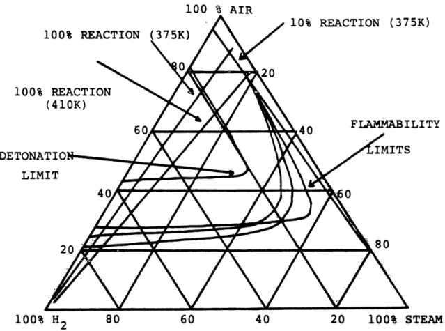
The combustion literature contains innumerable studies of various hydrogen reactions. Sherman et.al.[ 16] provide a general review of important implications in nuclear safety. Figure 2.1 is abstracted from that work and depicts the parametric dependencies of constituent
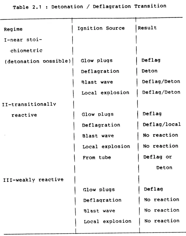
concentrations and thermodynamic state. Hertzberg and Cashdollar [17] present a review of current theoretical understanding of the size and shape of the flammability limit surface in containment volumes. J. C. Cummings et.al. [18] report work performed at Sandia National Laboratories in which qeometrical effects are studied. Jaunq et.al. [19] analyze the containment atmosphere system to better understand the transition from
deflagration (subsonic orooagation -i.e. flame) to detonation (sonic wave prooaqation). Table 2.1 is
100 % AIR 100% REAC' 100% REACTION (410K) DETONATION--... LIMIT 10% REACTION (375K) A . FLAMMABILITY 80 60 40 20 100% STEAM
FIGURE 2.1:FLAMMABILITY AND DETONATION LIMITS OF HYROGEN - AIR - STEAM MIXTURES
100% H2
80
20
taken from that work. Finally Kumar et.al.[20]
empirically investigated parametric effects at high concentrations including sensitivity to steam
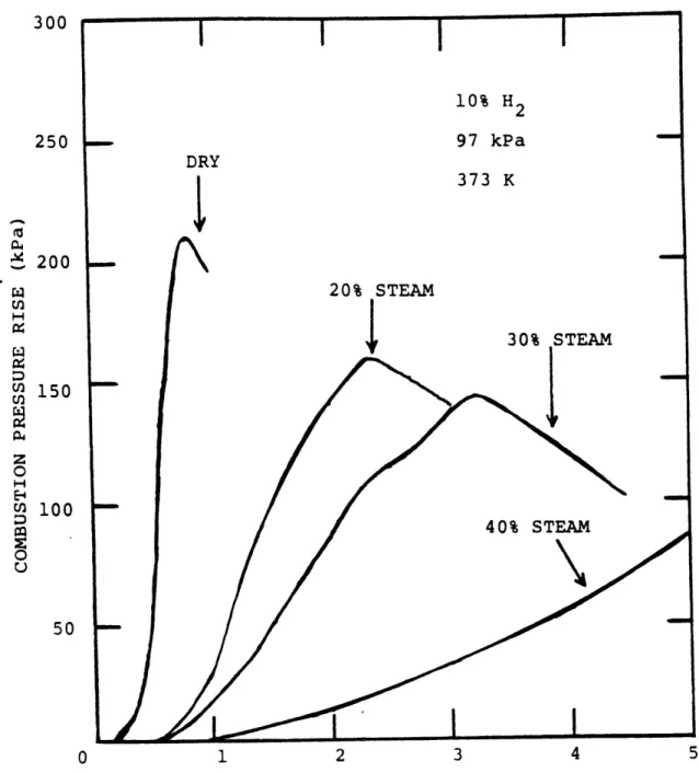
concentration and obstacles. Figure 2.2 illustrates on of their more important results. Steam is shown to restrain both the magnitude and extent of the hydrogen reaction.
The issue of post-accident hydrogen control is directly related to the underlying scenario assumptions.
If a small core oxidation source is assumed as was
required by the regulatory authorities prior to the TMI 2 accident [21], control involved demonstrating conformance analytically through safety analysis and through physical installation of relatively small recombining devices to handle the weaker radiolysis source. The regulatory
perspective has distinctly changed after the accident as is evidenced in the presentation of Butler et.al.[22]. The control measures described in this work are
classified as either preventive and mitigative.
Preventive measures most frequently involve enhanced emergency core cooling systems. This enhancement is sometimes guided by probabalistic risk assessment (PRA)
(see Boyd et.al.[23]). Potential mitigative measures include pre-accident inerting, Dost-accident inerting, deliberate ignition, filtered-vented structures,
water-fogging and catalytic absorption. Demonstrating the necessity and efficacy of any of these ootions is the underlying motivation for this and many other studies
Table 2.1 : Detonation / Deflagration Transition Regime I-near stoi-chiometric (detonation oossible) [I-transitionallv reactive III-weakly reactive Ignition Source Glow plugs Deflagration Blast wave Local explosion Glow plugs Deflagration Blast wave Local explosion From tube Result Defla Deton Defla Defla g g/Deton g/Deton Deflag Deflag/local No reaction No reaction Deflag or Deton Glow plugs Deflaqration Blast wave Local explosion Deflag No reaction No reaction No reaction i I
300 10% H2 250 97 kPa DRY 373 K 200 20% STEAM
S30%
STEAM o 150 H UM 100 g 40% STEAM 0 50 0 1 2 3 4 5TIME AFTER IGNITION (SEC)
(see Thompson [24].)
2.2 Relevant Computational Methods
Prior to the citation of works of narrower scope, a few qeneral references are noted which are used
throuqhout the analytical development. First, the
pioneering text of Richtmeyer and Morton [26] addresses the general topic of numerical solution of initial-valued problems. Of particular note are the review of finite difference approximations and their associated accuracy and stability characteristics (see Chapter 8 of that reference). Roache [27] has provided an encyclopedic review of most schemes utilized in the area of
computational fluid dynamics. The stability analyses of each scheme orovides an excellent overview to Aid in the selection of appropriate techniques. The stability
analysis of finite difference equations desctibed by Roache is based to a larqe extent on the work oE Hirt [28]. More recently Patankar [29] focuses on a single but quite qeneral flow solution methodolqy (ie. Semi-Implicit Method for Pressure-Linked Equations or SIMPLE) and also provides a basic understanding of the application of
finite difference techniques to the solution of fluid and heat transfer problems. Ransom and Traoo [30] have
presented a short but thorough review of the use of various computational methods in nuclear thermal
hydraulic analysis. Finally, while there are many techniques, most are based on aoolying the procedures
of numerical analysis, especially of linear systems. In this regard, the text of Isaacson and Keller [31] is useful for the specification of desirable numerical methods such as the inversion of banded matrices.
The solution method used for the solution of the rapid blowdown problems is the Implicit Continuum Eulerian (ICE) technique developed by Harlow and Amsden [32]. The technique allows a stable solution limited by the material Courant time step (ie. 6t<6x/u) rather than the full Courant limit (6t<6x/u+c) tyoical of other
compressible flow techniques. Rivard and Torrey [33] applied this technique coupled with a two-phase flow
formulation due to Ishii [34] to develop the K-FIX code which was the fluid solution subprogram of the BEACON code. A very efficient method applicable to
incompressible oroblems is the Simplified Marker and Cell or SMAC procedure developed by Amsden and Harlow [35]. It is closely related to the ICE method in both its
semi-imDlicit iterative procedure as well as its discretization logic.
The Courant limitation is rather restrictive in longer duration simulations in which the flow
characteristics change slowly in time. In order to
eliminate this restriction the use of implicit techniques deserves consideration. The application of completely
implicit techniques to pure diffusional problems of the form
af = V * F V T (2.1) at
is straightforward. An especially efficient technique is the alternating direction implicit (ADI) method.
Important theoretical considerations of this class of methods are provided by Douglas and Gunn [36]. The application of analogous methods to mixed convection/ diffusion problems characterized by
aT + V * uV' = V * r VY (2.2) at
is more complex and not generally amenable to closed form stability and accuracy analysis. Briley and McDonald
([37] and [38]) have analyzed these nroblems under the general heading of linearized block imolicit schemes. They point out that the consistent splitting of the directional sweeps is crucial to a method's success. Nevertheless, the application of the methods described
by Briley and McDonald are limited to fully compressible problems since a necessary validity condition is the presence of each dependent variable in a time derivative
in at least one equation. In an incompressible problem density does not conform to this constraint.
Stability is not the only computational
consideration. Accuracy is of equal importance. This is particularly true in cases when physically diffusive mechanisms are encountered in convective problems. The discretized treatment of convective terms usually gives
diffusional nature. This so-called numerical diffusion must be carefully assessed in order to ensure that the
numerical solution technique does not produce an unrealistic physical solution. The work of Huh [39] addresses this problem as it relates to hydrogen
transport analysis and it should be consulted for a more thorough treatment of the topic.
Some early higher order techniques are discussed by Roberts and Weiss [40]. The greatest
limitation of these early techniques are the prohibitive storage and computinq effort associated with correcting convective term inaccuracies. Similar methods are
discussed in a review paper by Fromm [41]. More recently, workers have studied Lagrangian-based techniques. Typical among these is the work of Raithby ([42] and [43]) who
surveys various upstream differencing techniques and develops an original skewed differencing which he claims
can significantly decrease false diffusion in some
oroblems. Chang [44] studied a number of these methods in terms of a method-of-characteristics (MOC) solution. (See Weisman and Tentner [45] for a general review of MOC
application to nuclear engineering problems.) Chang
emphasizes that the interpolation method used to estimate the upstream path value of the convected entity
significantly affects accuracy and physical
reasonableness. A related approach termed the tensor viscosity (TV) method has been reported by Dukowicz and
Ramshaw [46].
The numerical solution of turbulent flow problems usually involves simplifying assumptions in
order to render the problem tractable. Invariably, higher order correlation functions arising from the expansion of the primitive flow variables into constant and
fluctuating components are grouped together to define a reasonable physical characteristic of the average flow. The algebraic eddy viscosity approach is the simplest approximation since no additional conservation equations require solution. Unfortunately, algebraic and first order approaches (such as mixing length hypothesis) are
inadequate for recirculating flow analyses. A general introduction to these considerations is provided by Launder and Spalding [47] in a series of published
lectures at the Imperial College in England. Second order methods in which additional conservation equations for two turbulence parameters such as turbulent kinetic
energy and dissipation are generally accented as the best current alternative. The review article of Lumley [48] is useful for ascertaining a physical interpretation of second order methods. Rodi [491 presents a number of second order methods applicable to atmospheric transport problems.
These models are also useful in the present application since buoyant turbulent production is a significant driving force in both physical regimes.
relate to the solution of continuum problems. Lumped parameter or nodal methods are also very useful
analytical tools. The pioneering work of Porsching et al. [50] addresses the stable numerical integration of
conservation equations for hydraulic networks. The technique is semi-implicit which is a highly
desirable characteristic since an explicit time step stability constraint is quite prohibitive in most oroblems of this type.
2.3 Containment Analysis Tools
Analytical models of nuclear containment response to accidents have evolved from simple lumped parameter analysis to continuum modelling. The chief application of these tools are the assessment of
containment integrity and providing boundary conditions for nuclear steam supply system analysis. The lumped parameter analysis codes are exemplified by the CONTEMPT
series of programs (see D. W. Harqroves et.al.[51] for examole). As the requirements for accuracy and improved spatial resolution increased, multi-comoartment analysis tools were developed. The CONTEMPT4 program described by L. J. Metcalfe et al. [52] addresses the behavior of a wide range of containment designs including dry
containments, suppression pool designs, ice condensers and others.
As hydrogen related issues gained imoortance, basic lumped parameter models were extended to handle
the transport of additional non-condensibles. The fRALOC code developed by Jahn ([53] and [54]) is an examble of this approach. Some distinguishing characteiistics of the RALOC code are its explicit modelling of hydrogen
generation rates, treatment of component diffusion and mixed implicit/explicit integratiOn methods. An
assessment of this program is reported by Buxton et.al. ([55] and [56]). They conclude that the codi produces good qualitative results and fairly stable numerics. Areas worthy of improvement are expansion of base set of components, multiple source injection logic, improved heat slab modelling, removal of the saturation constraint and allowance of user-controlled loss resistances. The last point is particularly salient to the distusion of
all lumped parameter tools. These modeli are very well suited to scoping or global analysis. ihe
application of these methods to the ptediction dt detailed spatial distributions is hindered by the
inability of the basic conservation model to hahdie local effects. One of the major restrictions is the rather
arbitrary specification of junction characteristics such as resistance or inertia when modelling an essentially open space. Fujimoto et.al. [57] report the development of a code named MAPHY (Mixing Analysis Program of
Hydrogen) which seems nearly identical to RALOC except for a completely implicit integration logic. Fischer et.al. [58] report the development of the WAVCO program
for the analysis of general non-condensible transport in containments including hydrogen and CO2 (from
core/concrete interactions during meltdown events). The model includes a treatment of sump water dynamics.
The analysis of hydrogen behavior in
containments is more complex when chemical reactions are considered. Lumped parameter tools are reasonable in this regard if the analyst is interested in bounding
temperatures and pressures. The HECTR code developed by Camp et.al. [59] at Sandia Labs is a recent example of
such a program. In addition to the usual nodal flow models, HECTR includes a hydrogen burn and radiative heat
transfer models. The burn model is conceptually simple since actual chemical kinetics cannot be modelled in a lumped code due to the dependence of reaction kinetics on local conditions. Deflaqration is assumed to be initiated after a user-defined global concentration level is
achieved and flame speed is computed using an empirical correlation of the form
flame speed = A xh + B, (2-3)
where: A,B = empirical constants,and x = mole fraction.
The burn completeness can either be user specified or an additional internal emoirical correlation is employed.
If spatial definition is important as is the case in assessing many hydrogen safety questions, a continuum problem must be solved. A one dimensional
formulation is an intermediate step between lumped parameter models and multi-dimensidnal analyses. It is most appropriate for problems where variations in a
preferred direction dominate dynamic effects. Willcutt and Gido [60] and Wilcutt et.al. [61] have discussed application of this approach to hydrogen transport. The flow formulation depends heavily upon boundary layer
approximations to define the field. The method is applied to the analysis of radiolytic hydrogen source in a single room. Molecular, turbulent and buoyant effects are
treated separately and together in order to assess
individual contributions. The aPolication of this method to single region Problems with well-defined boundary conditions can accrue the benefits of a more
sophisticated multidimensional analysis with considerably reduced computational effort.
Pinallv, multi-dimensional models are
available. The BEACON code described by Broadus et.al. [62] is of central importance to this work. Its basic formulation allows the treatment of fluid regions in terms of zero (lumped), one or two dimensional zones. Two-phase continuum equations describe the
multi-dimensional regions from an Eulerian viewpoint. The program includes explicit models for transient heat
conduction in solids and condensate film dyhamics. This code is more fully described in the next chapter. Other continuum programs are beinq apolied to the hydrogen
problem. Trent [63] and Trent and Eyler [64] have modified the single region TEMPEST code to track
hydrogen. This program allows three (or two) dimensional modelling of a single region includinq heat conductinq solids. Turbulence is modelled through the use of a two equation closure model. The HMS (Hydrogen Migration Studies) program developed by Travis ([65] and [66]) is based on a compressible flow solution using the ICE method. Three dimensional single room modelling is
employed. Mixing enhancement due to turbulence is handled by an input eddy viscosity. Component diffusion is not
taken into account in the soecies transport equations. Thurgood [67] has applied the two-phase code COBRA-NC to
these problems A couoled two-field (gas and liquid) solution is accomplished in continuum reqions while a lumped ootion also exists.
3.0 Analytical Modelling 3.1 Overall Approach
In the interest of efficiency and to minimize the
duplication of effort, the starting point of this analytical development is an existing containment code. As noted in
Section 2.3, the BEACON code possesses a number of features necessary for the valid simulation of hydrogen transport transients and this program provides the superstructure upon which the overall tool is built. The justification for using
BEACON rather than another code or developing a completely new code is first presented in this section. Following this, the two-stage development/modification is described. These discussions demonstrate that the final product is substantially different from the original code.
There are six major characteristics favoring the choice of BEACON. First, it was developed with modelling options
such as compartment geometries, input specification and
material property data representative of containment problems. Second, the internal code structure is distinctly modular. This feature allows modification of one submodel without
serious impact on unrelated models. The computer application discussion of Appendix A further demonstrates this 'top down' programming approach. Third, BEACON's treatment of fluid regions is substantially more versatile than most containment codes in that a region can be modelled as zero-dimensional
(lumped parameter), one-dimensional or two-dimensional
be invoked in a single problem such that multi-compartment problems with user specified spatial resolution are possible.
The pre-chemical reaction flow transient as well as the chemical kinetics of hydrogen reactions are strongly influenced by the presence of water. Therefore, the inclusion of
condensate film formation and behavior in the original code is a desirable characteristic. Local containment thermal conditions are determined in part by the interaction with
structural heat sinks such as walls, gratings and equipment. These structures themselves experience thermal transients over the course of an event. The BEACON code contains a
one-dimensional heat conduction model to handle these effects. Finally, the code is available at relatively little expense on a timely basis from the National Energy Software Center.
The requirements of hydrogen analysis in conjunction with the basic deficiencies of the BEACON code specify the required development effort. The basic continuum formulation of the program involves a complex two-phase multi-equation
dynamic model with the provision of non-equilibrium inter-phasic mass, momentum and energy transport in a fully
compressible format. The original components are water in gaseous or liquid phase and air. Air and water are also the
only allowed components of the lumped parameter, condensate film, heat transfer and transport property calculations. These limitations define the first modification step such that hydrogen is consistently included in all the basic models. The resultant product of this first step is a tool
with the ability to handle hydrogen transport during rapid blowdown transients dominated by compressibility and two-phase flow effects.
The inherent limitations of the BEACON program
necessitates the development of a completely new slow mixing model. In a slower transient, non-equilibrium
thermo-dynamics, multiphase transport effects and total fluid
compressibility are not as important as buoyancy, molecular and turbulent diffusion and compositional changes. The development of an appropriate formulation and solution methodology is detailed in the discussions of section 3.3. The new models are independent of the original BEACON
equation set. Particular aspects of the new subcode are: basic model formulation, turbulence modelling, consistent definition of thermodynamic state and detailed consideration of the accuracy and efficiency of the computational scheme. The validity bounds of the new model are also specified.
A substantial amount of time and attention are involved in the acquisition, installation, modification and validation of any large computer program. The work reported here is no exception to this general rule. A number of computer
application topics are addressed in Appendix A. This appendix interfaces with the analytical discussions of sections 3.2 and 3.3. More information is contained in the new code's
3.2 Modification of the BEACON Code for Rapid Transients The modification of the BEACON equation set for the analysis of rapid blowdown events is divided into four sub-topics. First, the inclusion of hydrogen in the continuum equations and solution logic is described. Second, the treatment of hydrogen in lumped parameter formulations is specified. Following this a number of smaller ancillary model developments are detailed including basic thermo-dynamics, hydrogen and mixture transport properties, the effect of hydrogen on condensate film dynamics and heat transfer aspects. Finally, the inherent limitations of the modified BEACON equations are set forth. In many instances,
the original program documentation is a useful accompanying reference for this section.
3.2.1 Continuum Equations and Their Solution
The original BEACON continuum formulation is best suited for the analysis of rapid transients. The formula-tion is actually based on the K-FIX code. The model
derivation includes non-equilibrium interphasic exchanges. The revised equations are presented below in an abbreviated manner since the exact form of the various exchange functions
is not central to this discussion. A thorough treatment of the multifield model equations is provided by Ishii [34].
The major alteration is the addition of a fourth mass balance to represent hydrogen transport. The following mass conservation equations are solved:
v + (pu ) = J - Jc (3.1) t g-g e c S+ (p u) = - Jc, (3.2) - g -c at + V * (p u ) = 0, and (3.3) g -g + V (u ) = J - Je (3.4) at - = c e
These equations are fully compressible in formulation and the evaporation/condensation source terms are calculated using non-equilibrium thermodynamic models. Diffusional transport of the individual compounds is neglected. In a more conventional formulation the first equation might be
replaced with a mass balance for component 3 (air) such as
93 + V (p u ) = 0. (3.5)
at - -g
Nevertheless (3.1) is the sum of equations (3.2) (3.3) and (3.5) and thus represents a consistent formulation.
Each phase is described by energy conservation equations. modified and are presented here
can be seen and compared to the time momentum balances are:
its own pair of momentum and These equations were not
so that their general structure new slower mixing model. The
ap u 9 + V ( u u ) = at g-g-g - aVP + V a +p f+ f (U l J - ) (3.6) -g g- -M -g e and +t + ( U u) = (a-l)VP + V*(l-a) + P f - f (U g t Je Jc ) " (3.7)
The f function represents non-equilibrium interphasic -M1
momentum exchange due to velocity slip and phase change. The shear stress tensor embodies only molecular effects including bulk viscosity using Stoke'shypothesis. The neglect of
turbulent-enhanced viscosity is a reasonable simplification in blowdown calculations. f represents body forces such as gravity.
The two energy equations are: pg e + (p
e
) = -P [-. + Vctu
I + ao : Vu at 9 g-g at- -g -- g + V kg VTg + fE (U ,u , J - Jc,Tg - T, efg), (3.8) -t + V " (pze u) + (l-a)c :Vu - fE (u - u , where a. :Vu. E a.. 1 -113
ax
= P [ (t + V (l-u) u ] + V k VTk Je - Jc, Tg - T, efg), (tensor notation).In analogy to f , fE describes the non-equilibrium inter-phasic exchange. A number of possible exchange models are available as options but the analyst should be cautioned that all models save for the model of Crowe et al. [68] do not account for the presence of an inert gas such as hydrogen or air at the interface. As such, option choice must be based on the conformance of the problem to the constraints of the exchange model. As a general remark, it is felt that any of
these rather complex, semi-empirical and restricted scope
models are of limited usefulness to hydrogen-related questions. and
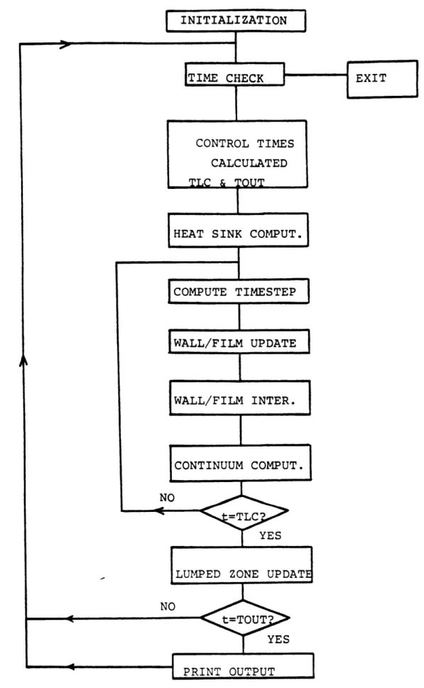
The basic numerical solution methodology of this modified equation set is not changed. The code allows different computational time step sizes for different regions and processes. The basic time advancement logic
is shown in Figure 3.1. As such time steps in lumped
parameter regions and solid heat sinks of reasonable thick-nesses are usually larger than those of the Eulerian fluid regions. The fluid solution technique involves casting the differential equations into a finite difference staggered mesh (see section 3.3) and solving the resulting coupled
algebraic equations by an implicit point relaxation scheme. Due to the coupling logic used to relate the momentum and mass equations the stability limitation of the time step
is independent of sound speed but constrained by the material Courant-Freidrichs-Levy (CFL.or Courant) condition of
X.
6t < _ (3.10)
i max
Due to the coupled nature of the conservation equations, a number of nested iterative operations are required to arrive
at a converged solution. A more detailed treatment of this technique, which is named Implicit Multifield (or IMF), is provided by Harlow and Amsden [69].
FIGURE 3.1: BASIC TIME ADVANCEMENT LOGIC CONTROL TIMES
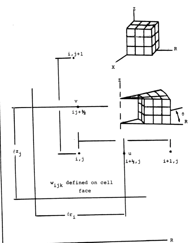
FIGURE 3.2: COORDINATE SYSTEMS DEFINITIONS FOR CONTINUUM REGIONS i,j+1 ...- * ij + 04
ij
iljwijk defined on cell face
I
i+1,j
3.2.2 Lumped Parameter Zones
The original program possessed the capability of treating large regions in which spatial variations are not important as zero-dimensional or lumped parameter zones. The regions are assumed to be perfectly mixed and mass and energy are balanced on a control volume basis. Flows to and from these zones are computed by modelling the connecting junction as a one-dimensional Eulerian region. This approach is restrictive for two reasons. First it necessitates employing a continuum model when merely average junction flows are required.
Second, the balance equations are solved explicitly in time which makes long term computations costly. Therefore two
lumped parameter related developments are described. First the existing BEACON approach is extended to handle hydrogen and second, an entirely new treatment which requires no continuum solution and is completely implicit in solution formulation is added as an additional option.
3.2.2.1 Inclusion of Hydrogen in Existing Formulation A balance equation for hydrogen of the following form is added
V p = Z (p u A) + Z(m ) • (3.11)
L d- g2 92 9 g 2
i=all boundaries j=all sources
The remaining energy balances are modified to account for
limitation of the original formulation is that the nodal balances are specified as to be compatible with the two-phase non-equilibrium model and as such the lumped parameter state solution exhibits the same limitations as the continuum solution.
3.2.2.2 Model Improvement
In light of the limitations elucidated above, a new lumped parameter model is developed.. The formulation presented is based on thewell-established nodal solution methodology used in the RELAP and FLASH programs and as such only the essential points are presented. Three nodal
mass balances are used.
Mik = W. - W. +SMik,
ik j Pj
(3.12) j=to junctions j=from junctions
where: k = air, hydrogen and water and i = node.
The nodal energy conservation equation is d U = h. W. - Eh. W.
dt i 3 3 1 3
j=to junctions j=from junctions
+ ESMik hsk, (3.13)
k=1,3 where: h = 1[U+pV] and
hsk = source enthalpy. sk
Momentum is conserved using a junction to describe the flow from node K to node L. Junction inertia, differential nodal pressure, frictional resistance and elevation differ-ences describe the junctions' temporal behavior.
K. Sign(W.)W2
Ij d W (P L) - 3 2 + P j g6z j ] . (3.14) 3 dt W K L 2A 22Ajpj
This model formulation requires the solution of 4 ordinary differential equations (ODE) for each node and one ODE for each junction such that a system of I nodes and J junctions requires the simultaneous solution of 41 + J coupled rather stiff differential equations. The strong coupling suggests an implicit method is required in order to attain a stable
solution. The particular implicit solution procedure was first introduced by Porsching et.al. The 41 +J system is formulated in a vector fashion with a state vector defined as follows:
W wJ Mal aI Mhl S = : . (3.15) MhI Mwl wI Ul
and the system is described by: dv
- = f(Z,t) . (3.16)
A Taylor series expansion of the vector function, f, in-cluding only first order terms and assuming a forward time difference for the left hand side is
n+l n
nt
= f( tn) + n+- n) . (3.17)6t Y a n n Y_
The terms of the Jacobian matrix are evaluated assuming the state variables are independent of each other. Under this constraint, the junction mass flow difference equation is
6t 2A 2 (I -W I KP n+l n P n+1 n U MK K K L L + ()(n+~1)-UnL (Un+1 + 1 n_ pn J3 + h nK L 2 n I. J -2A 3 p 3
The nodal mass and energy balances are of the form
1 1 6t n+l_ n n - ((wn+l_ n + wn J J I ) J J j=to junctions + SM. 1 j=from junctions (3.19)
u
+1
_U
n 1 1 [(n+l Wn ) + Wn]h 6t j -3 W j=to junctions - [(w n +1 _ Wn) + Wn] + SM.h . (3 j=from junctionsThe mass and energy balances can be substituted into the junction equations to reduce the system to order J. The resulting matrix equatio.i is
An AWn = Bn (3
(3.18)
and
.20)
where Ais a JxJ square coefficient matrix and AW (= Wn+l-W n) and B are vectors of length J. The matrix elements are
Sign(Wa1) 2 A. = 1- t F + () + () + () h S"a I. (M)K aM) L aU Kj + () Lhj , (3.22) where Fn j
2p
IjA2
K" inWjj2 W n n ifn > 0 hn if Wn < 0 L j A 13 isj 2 F1((I
p )K+ ( ) KhiK))+ F( ( )L + ( ) Lhik) Ij T K + K P LP 0 if Wni F1 = 1 if Wn 1-1 if w
n t0 if Wn F2 = 1 if Wn 1-1 if
W.
n
I (3.23) is not to or from K is from K is to K, is not to or from L is to L is from L, 1 n n h [(1+ Fl)h + (1-Fl) h of junction i and iK 2K L of junction i 1 + (1-F2)h] iL 2 K of junction i and where6t n n K- n4 B - 3 3 + p g 6z j j I K L 2p 3 A2 L j 6t 1K 2K 1L 2L + 5. 3 [FIK + F2K- FIL- F 2L (3.24) where 3 aP F I xk (SMx + xk W - x .Wn) ix = k= axk xk kjj kj '
j=to junctions j=fromjunctions and 3 ap F3 aP k (SM h + I x .Wnhn 2x I U x (Sxk sxk kjj jk k=1 xk j=to junctions - I X Wnhnkx)
3 3 3
j=from junctionsThe equation set must be closed with state relations in order to evaluate the various partial derivations of pres-sure. A mixture perfect gas law coupled with an assumption of a saturated liquid state leads to the following represent-ative relations: x MRT x RT aP a gx x x x gx x x(325) x gx gx x - [ ] , (3.26) gx Pg P 0 (3.27) R Xxa Ra x x R + Xxs x xa a xh h xs s