An Analysis of Residential Window Waterproofing Systems
by Austin Parsons
Master of Environmental Studies Dalhousie University, 1998
SUBMITTED TO THE DEPARTMENT OF ARCHITECTURE IN PARTIAL FULFILLMENT OF THE REQUIREMENTS FOR THE DEGREE OF
MASTER OF SCIENCE IN BUILDING TECHNOLOGY AT THE
MASSACHUSETTS INSTITUTE OF TECHNOLOGY FEBRUARY 2004
C 2004 Austin Parsons, All rights reserved. The author hereby grants to MIT permission to reproduce
and to distribute publicly paper and electronic copies of this thesis document in whole or in part.
Signature of Author:_____
Department of Architecture January 16, 2004
Certified by:
Leon R. Glicksman George Macomber Professor of Construction Management Professor of Building Technology
Thesis Supervisor
Accepted by:
I
Stanford AndersonProfessor of History and Architecture Chair, Department Committee on Graduate Students
MASSACHUSETTS INSTrIrTE OF TECHNOLOGY
JUN
2
8
2004
L!BRARIES
An Analysis of Residential Window Waterproofing Systems by
Austin Parsons
Submitted to the Department of Architecture
On January 16, 2004 in Partial Fulfillment of the Requirements for the Degree of Masters of Science in Building Technology
Abstract
The prevalence of vinyl nail-on windows in the North American new home construction market has prompted ASTM International to write ASTM E2112-01 "Standard Practice for Installation of Exterior Windows, Doors and Skylights". This thesis focuses on the window jamb flashing recommendation in ASTM E2112-01 for vinyl nail-on windows by asking the question of whether a vinyl window's integral nail-on flange is by itself an adequate jamb flashing.
To answer this question, the Jamb Drip Test was designed and completed on fourteen (14) window/wall details. The answer to the question depends on the window/wall construction sequence. When the weather resistant barrier (WRB) is installed prior to the window, it isn't. When the WRB is installed after the window, the nail-on fin is by itself
an adequate jamb flashing.
Based on this Jamb Drip Test study, a recommended window/wall construction sequence
of sheathing- flashing (sill, jamb and head) - vinyl nail-on window - WRB - siding
option is proposed. This sequence recognizes that while the nail-on fin may be an adequate jamb flashing, without flashing, the designer cannot take full advantage of the symbiotic relationship between the nail-on flange and the space it creates between the adjoining building elements (e.g. sheathing and the WRB). In this capacity, jamb flashing is added to the construction sequence to protect the sheathing from wetting and aid in directing incidental water to the exterior.
Based on this proposed construction sequence, effort was focused on improving the present state of the art window/wall weatherproofing detail. An alternative to the use of high performance sealant to create the seal between the flashing and the window's nail-on flange is proposed. The present recommendatinail-on uses a nail-one-piece folded sheet that envelops the window flange, WRB and at the same time incorporates the window flashing function.
This novel, dual function (window seal + window flashing system) product is called w-Flashing. The thesis ends with a description ofw-Flashing's performance attributes, prototype design and recommended installation sequence around a vinyl nail-on window. Thesis Supervisor: Leon R. Glicksman
Title: George Macomber Professor of Construction Management Professor of Building Technology
Acknowledgements
This degree would not have been possible without the support and sacrifices of my family. I have a special wife. Christene never complained, always supported me, never let me get too down, or too full of myself and through her example, taught me a great deal about commitment. My parents have always been there for me, and this latest adventure has been no different. They not only shared their house with me, but were quiet sounding boards who altered their lifestyle to provide me with a distraction free environment.
Keith McCluskey helped in taking the photographs and set up for the Jamb Drip Tests and the installation sequence for the w-Flashing. He also took the time to proof read a draft version of the thesis. I couldn't have done this work in half the time or as efficiently without him.
I would like to thank Mr. Thomas Russell, Vice President - Manufacturing and Mr. William Correia, Plant Manager of Harvey Industries, Inc. for their time, and interest in this project. Through their efforts, Harvey Industries, Inc. provided the window frames for the Jamb Drip Tests and the w-Flashing construction sequence. Thanks to Mr. Fred Baker, Corporate Technical Director of the Fortifiber Corporation for his time and providing me with flashing samples.
MIT provided me an opportunity to learn. I will always consider my time at the Institute as special. I not only learned a great deal from my courses, but I will always treasure the conversations with faculty and students. Finally, I would like to thank Dr. Leon
Glicksman for providing me not only with the opportunity of studying at MIT, but the time to finish this degree.
Table of Contents
ABSTRACT 3 ACKNOWLEDGEMENTS 5 TABLE OF CONTENTS 7 LIST OF FIGURES 10 LIST OF TABLES 12 1.0 Introduction 13 1.1 Principles 171.2 Controlling Above Grade Water Flow: Surface Barrier Walls and 18 Membrane/Drainage Walls
1.3 Residential Window Types 19
1.4 Making a Residential Window Watertight 20
1.4.1 The Role of the Window Flashing System 21
2.0 Is the Nailing Fin an Adequate Jamb Flashing? 23
2.1 Jamb Drip Test
2.1.1 The Construction of the Base Window /Wall Assembly 27 2.1.1.1 Description of the Cedar Clapboard and 28
Vinyl Siding
2.1.1.2 The Design of a Clear Clapboard 30
2.1.1.3 Siding Options 31
2.1.2 The Procedure Used to Introduce a Measured Amount 32 of Water at the Junction of the Window's Head Nail-on
Flange and the Jamb Nail-on Flange
2.1.2.1 Water Introduction Points 33
2.1.3 Recording the Path Taken by the Water as it Travels 34 Down the Window Jamb under the Influence of Gravity
2.1.4 Drip Jamb Test Procedure Recap 35
2.2 Water Drainage Paths 36
2.2.1 Test 1: no WRB or Clapboard, Water Introduced Over the 37 Nail-on Fin
2.2.2 Test 2: no WRB, Clear Clapboard, Water Introduced Over 38 the Nail-on Fin
2.2.3 Test 3: no WRB, Cedar Clapboard, Water Introduced Over 39 the Nail-on Fin
2.2.4 Test 4: no WRB, Cedar Clapboard, Water Introduced Next 40 to the Nail-on Fin
2.2.5 Test 5: no WRB, Vinyl Siding, Water Introduced Over the 41 Nail-on Fin
2.2.6 Test 6: no WRB, Vinyl Siding, Water Introduced Next to 42 the Nail-on Fin
2.2.7 Test 7: WRB, Clear Clapboard, Water Introduced in Front of the WRB Over the Nail-on Fin
2.2.8 Test 8: WRB, Clear Clapboard, Water Introduced Behind the WRB Next to the Nail-on Fin
2.2.9 Test 9: WRB, Cedar Clapboard, Water Introduced Behind the WRB Next to the Nail-on Fin
2.2.10 Test 10: 2.2.11 Test 11: 2.2.12 Test 12: 2.2.13 Test 13: 2.2.14 Test 14:
WRB, Vinyl Siding, Water Introduced Behind the WRB Next to the Nail-on Fin
WRB, Clear Clapboard, Water Introduced Behind the WRB Next to the Nail-on Fin
WRB, Cedar Clapboard, Water Introduced Behind the WRB Next to the Nail-on Fin
WRB, Vinyl Siding, Water Introduced Behind the
WRB Next to the Nail-on Fin
WRB, Strapped Wall, Water Introduced Behind the WRB Next to the Strapping
2.3 Conclusions
2.3.1 The Nail-on Fin in Isolation (Tests 1-6)
2.3.2 WRB (Tyvek Housewrap) Installed Prior to the Window (Tests 7-10)
2.3.3 WRB (asphalt felt) Installed after the Window (Tests 11-13)
2.3.4 Is the Nail-on Fin an Adequate Jamb Flashing? 2.4 A State of the Art Window/Wall Flashing System
Construction Sequence
2.5 Next Generation Window/Wall Flashing System
3.0 A Seal + Flashing System
3.1 w-Flashing System Installation Sequence
3.1.1 Modifying the w-Flashing Sill Detail to Allow Water Passage
3.2 A Critique of the w-Flashing System 3.2.1 Installation Concerns
3.2.1.1 The Relationship Between the w-Flashing Design and the Rough Opening
3.2.1.2 How Best to Install the Window into the Sheathing Through the w-Flashing
3.2.1.3 The Interface Between the Head Flashing and the Weather Resistant Barrier
3.2.1.4 The Time it Takes to Complete a w-Flashing Installation
3.3 The Next Steps
3.3.1 Selecting a w-Flashing Material
3.3.2 Modeling and Testing the w-Flashing's Performance 4.0 Conclusions and Recommendations
5.0 Reference
Appendix 1.0 ASTM E2112-01 (2002) 94
Recommended Window Installation Methods
AL.1 Method A: Weather Resistant Barrier (WRB) Applied after 95 the Window Installation - Flashing Applied Over the Face of
the Mounting Flange
A 1.2 Method B: Weather Resistant Barrier (WRB) Applied after 102 the Window Installation - Flashing Applied Behind the Face
of the Mounting Flange
A 1.3 Method Al: Weather Resistant Barrier (WRB) Applied Prior 109 to the Window Installation - Flashing Applied over the Face
of the Mounting Flange
A 1.4 Method B 1: Weather Resistant Barrier Applied Prior to the Window 118 Installation - Flashing is Applied Behind the Mounting Flange
A 1.5 Non-Finned Windows in Membrane/Drainage Type Walls 126
Appendix 2.0 Waterproofing Materials 136
A 2.1 Sealants 136
A 2.1.1 Silicone 136
A 2.1.2 Polyurethane 137
A 2.1.3 Latex Sealants 137
A 2.1.4 Plasticized Acrylic Latex Sealants 137
(a.k.a. Elastomeric Latex Sealant)
A 2.1.5 Block Copolymers 137
A 2.2 Flashings 138
A 2.2.1 Non-Stick Flashings 139
A 2.2.2 Peel and Stick Flashing: Rubberized Asphalt 139 (a.k.a. Bitumen Flashing)
A 2.2.3 Peel and Stick Flashing: Butyl Rubber 140
A 2.3 Weather Resistant Barriers 141
A 2.3.1 Asphalt Felt 141
A 2.3.2 Grade D Paper 142
A 2.3.3 Plastic Housewrap 143
A 2.3.4 Wrinkled Wraps 143
List of Figures
Figure 1-1: double hung window 14
Figure 1-2: vinyl nail-on window 14
Figure 1-3: nail-on window flashing detail 15
Figure 1-4: flush fin window flashing detail 16
Figure 2-1: typical flashing application 23
Figure 2-2: flashing application without the jamb flashing 24
Figure 2-3: typical base mockup assembly 27
Figure 2-4: cedar siding profile (finished side out) 28
Figure 2-5: cedar siding side profile 28
Figure 2-6: vinyl siding profile 29
Figure 2-7: vinyl siding side profile 29
Figure 2-8: clear clapboard profile 30
Figure 2-9: profile of the clear clapboard 30
Figure 2-10: installation of the clear clapboards on the mockup 31
Figure 2-11: Jamb Drip Test Set up 32
Figure 2-12: water introduction point directly over the nail-on flange (front view) 33 Figure 2-13: water introduction point next to the nail-on flange (front view) 33 Figure 2-14: water introduction point next to the nail-on flange (back view) 33 Figure 2-15: fluoroscein dye illuminated under white light 34 Figure 2-16: fluoroscein dye illuminated under black light 34
Figure 2-17: Test 1 drip pattern at the window head 37
Figure 2-18: Test 1 drip pattern at the window sill 37
Figure 2-19: Test 2 drip pattern at the window head 38
Figure 2-20: Test 2 drip pattern at the window head (side view) 38
Figure 2-21: Test 3 drip pattern 39
Figure 2-22: Test 4 water stains along the window jamb edge 40
Figure 2-23: Test 5 drip pattern 41
Figure 2-24: Test 5 drip pattern at the window sill 41
Figure 2-25: Test 6 drip pattern 42
Figure 2-26: Test 6 dot pattern 42
Figure 2-27: Test 7 drip pattern at the window head 44
Figure 2-28: Test 7 drip pattern along the entire length of the window jamb 44
Figure 2-29: Test 8 drip pattern 1 45
Figure 2-30: Test 8 drip pattern 2 45
Figure 2-31: Test 8 sill puddle 45
Figure 2-32: Test 9 drip pattern 46
Figure 2-33: Test 9 water pool above a clapboard edge 46 Figure 2-34: Test 9 fold in the WRB due to cedar clapboard installation 46
Figure 2-35: Test 10 drip pattern 47
Figure 2-36: Test 10 whip pattern 47
Figure 2-37: Test 11 drip pattern 49
Figure 2-39: Test 12 drip pattern 50
Figure 2-40: Test 12 drip pattern along the window jamb edge 50
Figure 2-41: Test 13 drip pattern 51
Figure 2-42: Test 13 drip pattern along the window jamb edge 51
Figure 2-43: Test 14 drip pattern 53
Figure 2-44: Test 14 drip pattern along the window jamb edge 53
Figure 2-45: lap joint between two clear clapboards 55
Figure 2-46: lap joint between two cedar clapboards 55
Figure 2-47: interlocking joint typical of the vinyl siding 55
Figure 2-48: space created by thickness of the nail-on fin 56 Figure 2-49: recommended vinyl nail-on window construction sequence 60
Figure 2-50: gap between the fasteners 62
Figure 2-51: water in the gap between the fasteners 62 Figure 2-52: ASTM E2112-01 recommended lap joint detail 63
Figure 2-53: sealant applied in the lap joint 64
Figure 2-54: modified lap joint detail 65
Figure 3-1: v-Flashing profile 67
Figure 3-2: location of the v-Flashing in the window/wall assembly 68
Figure 3-3: w-Flashing profile 69
Figure 3-4: location of the w-Flashing in the window/wall assembly 69
Figure 3-5: prototype w-Flashing profile 70
Figure 3-6:
j
channel profile 71Figure 3-7: L channel profile 71
Figure 3-8: constructed mockup 71
Figure 3-9: w-Flashing installation sequence - step 1 72
Figure 3-10: w-Flashing sill method 1 73
Figure 3-11: w-Flashing sill method 2 73
Figure 3-12: w-Flashing sill method 3 74
Figure 3-13: w-Flashing installation sequence - step 2 75
Figure 3-14: jamb - head detail - step 2 76
Figure 3-15: w-Flashing installation sequence - step 3 76
Figure 3-16: fastener detail - step 4 77
Figure 3-17: w-Flashing installation sequence - step 4 77 Figure 3-18: w-Flashing installation sequence - step 5 78 Figure 3-19: w-Flashing installation sequence - step 6 79 Figure 3-20: w-Flashing installation sequence - step 7 80 Figure 3-21: w-Flashing installation sequence - step 8 81 Figure 3-22: w-Flashing installation sequence - step 9 82 Figure 3-23 w-Flashing installation sequence - step 10 83 Figure 3-24: Harvey Industries, Inc. vinyl nail-on window side profile 84 Figure 3-25: w-Flashing installed %" proud in the rough opening 85
Figure 3-26: pinning the w-Flashing 86
Figure 3-27: head/jamb gap 87
List of Tables
Table 1: Forces that Lead to Moisture Penetration and the Associated 17 Critical Crack Size (t)
Table 2: ASTM E2112-01 Recommended Construction Sequences 21 Table 3: ASTM E2112-01 - Table 7 Installation Procedure Selection 94
1.0 Introduction
A building is designed and built to create a sustainable, comfortable indoor space. To meet this objective, the separate elements that collectively make up the building must perform as a system.
The building envelope - the roof, wall and foundation system - is one element of a building. The building envelope's role is to separate the indoors from the outdoors both physically and environmentally. Environmentally, the building envelope controls the flow of air, heat and moisture across the indoor-outdoor boundary. As with the whole building's performance, the exterior wall's performance as a space and environment mediator depends on whether the separate building envelope elements joined together to create the wall perform as a system.
Depending on how the wall is designed, this environmental separation is controllable. A properly designed wall can control the movement of wind, rain, solar radiation, heat, noise, insects, animals and people between the indoor and outdoor environment. To exercise the required control, the wall design must correctly resolve a set of competing
and conflicting requirements.
For example, windows are a means of controlling natural light and air into the indoor space. When a window is inserted into a wall, if not properly detailed, it can also allow uncontrollable wind, noise and rain into the indoor environment. The design challenge becomes one of providing a controllable entry point for light and air, but at the same
time, not compromising the wall's ability to control unwanted wind and water entry. The focus of this study is the in-service performance of a vinyl nail-on window's mounting flange I as a window jamb flashing. The nail-on window frame and its associated mounting flange or nailing fin was introduced in the California/Western United States new home market in the 1960s. Since then, the nail-on window frame has traveled west to east replacing the flush fin (a.k.a. brick mold) framed window as the most commonly installed window frame in the United States' new home construction market. This rise in popularity of the nail-on window frame has come with the rise in popularity of vinyl windows and is in part due to improvements in vinyl material, the cost of vinyl windows compared to windows made from wood and the low maintenance characteristics of a vinyl window (Russell, 2003 personal communication).
The nail-on window frame has a different frame configuration than the flush fin or brick mold framed window and the box frame window. As a result of these structural
differences, each window frame type has a particular installation and waterproofing procedure.
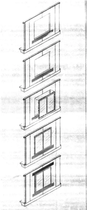
There are three residential window frame types. They include the nail-on fin window, the flush fin window and the box window. These window frame types are described in 1.3 Residential Window Types.
Interior Top Casing Interior Stop Insulating Glass -Meeting Rails Insulating Glass hithou Grids
Exterior Stop and /or Side Casing -amb
Intenior Apron -- Rough Sill
Figure 1-1 Double Hung Window Figure 1-2 Nail-on Window
source: AAMA (2000) source: AAMA (2000)
To inform window installers of the required installation procedures for a given window frame type, several installation guides have been written over the past decade (e.g. Bateman, 1995, JLC, 2003, McBride, 2002). ASTM International published an
installation practice in September 2002. The practice- "Standard Practice for Installation of Exterior Windows, Doors and Skylights" details a number of different procedures on how to install windows, doors an skylights into the fagade of a residential/light
commercial type building. The practice is intended to provide technical guidance to organizations that are developing training programs for installers of fenestration units (i.e. windows, doors and skylights) in low-rise residential and light commercial buildings. The recommended window installation details highlighted in ASTM E2112-01 (see Figure 1-3) are based on traditional window flashing details initially applied to flush fin framed windows (see Figure 1-4). If one references previous work in this field, the details highlighted in ASTM E2112-01 were first published in the AAMA Level RLC-1 training manual (2000) and Bateman (1995). In turn, in Bateman's work there is a direct reference to an earlier design guide (i.e. Thallon, 1991) that includes a flush fin window flashing detail.
IIIIMtIU6
L. 4TAPLt Im0?TUP
MaOV to 4ILL L 4L MPf P URt *.
kp4IFw. , unt Af AMPO
Pof-Eireo 6 at to Me0UN t40M" 4
Wit 4fe Poowr Wets ee tosa
4TAPLt LOWEtW E W ATNAjG 4 N. PO IT WLL LAP WALL ABWW 4 LOW W/ 4
MOK~IV GMMPt WON~* OSIIW. bM
A1%
WIbPW/ORA
IOPAt"i)I WAP -Figure 1-4 Flush Fin Window Flashing DetailtAT IrP OP of 110 W. Lnne es. IT K tTEftaseY IMPoMrruf o WRAP "10 0IG NI64 WITI A Meteidet MA B P
BBCAUU0 Wi 14 slUte
LU*4 Aft MT UrLKY to
Oc=5 4 SMCAIe *n* PM4O#1 i 24T WLO*A ALt A W024. Mt; paWeuwt 1 AteUATE N MWr I41AD WITUAT"OI4 00 WAU4t ALL LMVs% #tLAP A PPW ~ fIAT Dit4 ATer #AY M nie WiUCTiUALK PRAUt O
to swwp* 4IMP l
MngP" MAY t twPpto
mai xMusat VN a
der UKLY *S4aWZ Fo
Sl Tilt UM TIlW0 I0I, MARY
WU"t PItI *i Ae
M" TRW MOMOt MsIsess
P O4U A MrAr WmN) TIAT
M WILL r OLDUP V /ne ft PO * W1 WML LAYG
source: Thallon (1991)
The significance in noting this "reference trail" is recognizing that the flashing detail for a nail-on window is based directly on the flashing detail for a flush fin window. Given the differences in construction sequence between the two window frame types, the author
questioned whether the flashing details between the two window types had to be similar. In particular, there was a question about whether jamb flashing was needed for a nail-on window given the existence of the window's mounting flange and where this flange is located in the wall assembly.
This study is not theoretical in nature. It completes a series of physical modeling and testing studies. The information from these studies is then qualitatively reviewed. This
approach is in part a response to the difficulty of theoretically modeling water flow over and within a wall assembly, but also to what this study is attempting to achieve. A qualitative analysis is sufficient in terms of the recommendations made about the appropriateness of existing window flashing details.
The study's contribution to the field is two fold. It recommends a window/wall construction sequence for a vinyl nail-on window. It then introduces a novel window waterproofing assembly that both seals the window's mounting flange to a wall without the use of a sealant and provides a flashing system along a drain plane situated around the window's perimeter.
1.1 Principles
For a wall to leak, three conditions must exist. There must be a source of water, a force that pushes the water and a course that leads from the outside to inside. Water, in either its liquid or vapor state, can be made to move by a number of different mechanisms. The direction water moves for a given situation depends on what mechanism dominates (Addleson and Rice, 1991, DeFreitas et al, 1996).
Liquid water will flow downward under the effect of gravity, over the surface of the building or material. It can travel against the pull of gravity vertically and laterally by either capillary action (through porous materials such as soil, brickwork, plaster, timber, or between sheets of non-porous material in close contact), kinetic energy and/or external pressure gradients. Finally, as a gas, it can diffuse through air or porous materials under the influence of a vapor pressure gradient.
This study is concerned with unintentional rainwater entry. Condensation of internally or externally generated water vapor within the assembly is not considered. This
simplification is based on the study's objective and observations noted in the field. Most observed residential wall moisture problems are water-entry or leakage problems, not vapor condensation problems (Holladay, 2000).
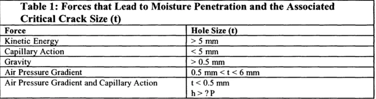
For rainwater to enter into a wall assembly under the influence of a given force, a course or hole must exist in the assembly. Once the size of the hole is determined, the designer can correlate the hole's size with the force(s) responsible for water mowment. The following table lists these relationships (Garden, 1963).
Table 1: Forces that Lead to Moisture Penetration and the Associated Critical Crack Size (t)
Force Hole Size (t)
Kinetic Energy > 5 mm
Capillary Action < 5 mm
Gravity > 0.5 mm
Air Pressure Gradient 0.5 mm < t < 6 mm
Air Pressure Gradient and Capillary Action t < 0.5 mm
h > ? P
Most moisture problems occur because there has been a failure to control either the force, source or course. This lack of control translates to an improper detail, (e.g. poor flashing practice (creating a course)), an unforgiving architectural detail (e.g. a flat fagade (not controlling the source)) or an improper product installation (e.g. a sealant that cannot adhere to a given substrate resulting in a gip in the air barrier (not controlling the force)).
1.2 Controlling Above Grade Water Flow: Surface Barrier Walls and Membrane/Drainage Walls
When a wall has the capability of managing rainwater entry it is considered waterproofed (Kubal, 2000). An exterior above grade wall can be waterproofed either as a surface barrier wall or as a membrane/drainage wall.
Surface barrier walls keep water out of the inner assembly by sealing the exterior surface with a waterproofing agent. They rely on sealarts around most building penetrations, including the windows, to prevent water from entering the wall assembly. They make no provision for drainage of incidental moisture that enters the wall space. These systems have little tolerance for construction variations or defects, or for compensating for through-wall cracks that develop as a result of weathering.
This is an "all or nothing" approach. The moisture-tight exterior surface is the wall's sole waterproof barrier. Examples of residential and light commercial sector barrier wall systems include some versions of EIFS (exterior insulation and finish system)2, concrete panels and single wythe masonry. The latter two examples are more common in light commercial buildings (Ruggiero and Myers, 1991).
A membrane/drainage wall waterproofing strategy (a.k.a. water-managed wall (Lstiburek, 2003)) is not an "all or nothing" approach. It is expected that incidental water will
penetrate the wall's outer surface. The design compensates for this "unintentional" entry by detailing a weather resistant barrier (WRB) behind the exterior surface. The role of the WRB is to collect and divert water back to the exterior.
The components of a membrane/drainage wall include the exterior surface (i.e. cladding), flashing system, weep holes, and the WRB.3 Examples of residential and light
commercial sector membrane/drainage wall systems include stucco, siding veneers, panels, shingles, wood shakes, metal panels, or tile.
2 An EIFS wall is a non-load bearing outdoor wall finish made up of a thermal insulation board, an attachment system, a reinforcement system and a compatible finish (ASTM E2112-01). EIFS systems are proprietary and different systems will have different requirements in terms of how to design and install the waterproof system.
3 If the wall is designed as a pressure equalized wall, then the WRB takes on the added responsibility of preventing air leakage across its plane. When it takes on this additional responsibility, it is sometimes referred to as a weatherproof barrier.
1.3 Residential Window Types
As implied in the introduction, windows are a typical component of a residential wall. A window can leak through the window unit itself or around the rough opening.4 Water
leakage through the window unit itself is a question of manufacturer quality control and is not discussed in this study. Water leakage through the rough opening is a question addressed presently.
ASTM E2112-01 describes various procedures on how to make the window/wall assembly waterproof. These procedures are based on two design variables:
1) whether the window unit is being installed into a barrier wall or a membrane/drainage wall; and
2) the type of window frame being used. There are three types of window frame assemblies:
1) flush fin or brick mold; 2) box frame; and
3) nail-on window.s
This window classification scheme is separate, or independent from the classification scheme that identifies residential windows according to how they open and close (i.e. double hung, casement, awning). Given this independence between schemes, it is possible to have a double hung window framed as a brick mold, box frame or nail-on window, and describe it as such.
A brick mold or flush fin is an exterior trim molding which forms a boundary between bricks or other siding and the window unit. The brick mold is positioned at or near the window's outside surface. The mold is left exposed and creates both the window's exterior trim and weather seal. The brick moldings are factory-applied to the window frame. The window is secured in the rough opening by nailing through the brick moldings into the framing members or by screwing through the shimmed head and side jambs.
A box frame (a.k.a. block frame or replacement window) has a boxlike appearance. It is delivered to the job site with no attached factory-applied flanges (i.e. flush fins). It is installed into the rough opening either by driving fasteners through the shimmed head and side jambs or by the use of installation clips or brackets.
Exterior moldings or casings may be supplied with the window for installation after the unit is secured in the rough opening. If not, they can be milled on site or at the builder's workshop.
4 A rough opening is the space between the wall frame and window unit. The rough opening is typically
the height of the window unit + %2" by the width of the window unit + %/".
5 A nail-on window is also referred to as a fin window, nailing fin or a flange window. These terms are synonymous and are used interchangeably in the text.
A nail-on window has a permanent 1 % to 2 inch vinyl mounting flange (a.k.a. fin) protruding from each side jamb of the window's body. Anchors (usually nails) penetrate the fin at intervals between 6 to 8 inches to secure the window to the wall. The nailing fin is later covered by siding or trim.
There are four types of nail-on windows: 1) Integral, structural flanges; 2) Integral, non-structural flanges; 3) Applied, structural flanges; and 4) Applied, non-structural flanges.
These categories define the window in terms of whether the flange's corners are fused together and whether the fin is installed in the factory or in the field. In this classification
scheme, integral implies that the flange is continuous and seamless.
While nail-on flanges can be applied or "snapped on" to a wood framed window, the most durable, problem free option is to use integral flanges. An integral flange can only be done with a window frame made from vinyl. It is applied in the factory, the comers are welded and it is part of the window jamb/frame extrusion. This construction results in a one-piece assembly that provides a continuous surface around the window perimeter. With the applied nailing flange, the corners are not welded, instead adhesive tabs are used as a bridging element. This detail creates a non-continuous assembly around the window perimeter. An applied flange would require more elaborate flashing and sealing details to ensure that the window mounting flange is watertight.
Structural implies that the flange can be used as an anchoring device or nailing flange and that the flange is capable of sustaining the structural load requirements of the fenestration unit in its location in the building. On the other hand, non-structural flanges must not be used as the sole means of anchoring the window (ASTM E2112-01).
The focus of ASTM E2112-01 and by default, the focus of this study is the nail-on window. However, all residential window frame types and wall assemblies must be made watertight. The different frame types dictate not only how the window is attached to the wall, but how it is made watertight. Recognizing these differences, ASTM E2112-01 includes procedures on how to make each window frame assembly inserted into either
a barrier wall or a membrane/drainage wall watertight. 1.4 Making a Residential Window Watertight
When installing a window into a barrier wall, independent of window frame, the
window/wall assembly is made watertight at the exterior joint between the window and wall. A brick mold window creates a fillet joint between the window trim and the wall
assembly. A nail-on window and box frame window create a butt joint. In the case of he nail-on window, this butt joint is between the window trim and siding. A box frame window creates a butt joint between the window jamb and wall assembly. The wall unit
is made watertight by extending the wall to the window jambs. There would be no exterior window trim in this (box frame) installation.
In terms of installing a nail-on, flush fin and box frame window into a
membrane/drainage wall, ASTM E2112-01 details specific step-by-step procedures with diagrams on how to make these window frames watertight. ASTM E2112-01
differentiates particular procedures or methods depending on the construction sequence. Four construction sequences are identified in the practice and are identified as Method A, Method B, Method Al and Method B 1. The following table identifies these Methods according the the construction sequence. Each method is presented in its entirety in Appendix 1.0.
Table 2: ASTM E2112-01 Recommended Construction Sequence
Method 1 2 3 4 5
A sheathing window flashing WRB' siding
B
sheathing
flashing
window
WRB'
siding
Al sheathing WRB2 window flashing siding
B1 sheathing WRB2 flashing window siding
Notes: The construction sequence is ordered by step starting at step 1. WRB: weather resistant barrier
1. The WRB in this instance would be #15 or #30 asphalt felt, Grade D paper or 3' wide strips of house wrap.
2. The WRB in this instance would be 5' to 9' width sheets of housewrap. 1.4.1 The Role of the Window Flashing System
The window flashing system is one component of a residential window waterproofing system. The WRB, the window fin (either a flush fin of a nail-on fin) and the siding are the wateproofing systems other components. The window flashing system's primary role is to collect and direct incidental water back to the exterior. From a water exclusion performance perspective, it integrates the window with the wall creating a continuous wet/dry boundary while compensating for the window and wall's separate movements due to thermal expansion (Addleson and Rice, 1991).
It is expected that the flashing system must prevent the flow of water into a wall due to gravity (Addleson and Rice, 1991, Lstiburek, 2003). As such, it is designed to work with gravity, using this force to direct water away from the wall. It controls gravity via the lapping principle creating a geometrical seal between the window and wall. In practice, the flashing system elements are overlapped so that "which is above overlaps that which is below" (McBride, 2002).
There is a range of possible materials one could select as a window flashing system. Given that the flashing system will get wet, the key consideration is that the material must be impervious to water.
ASTM E2112-01 defines the flashing system as the "integrated system of flashings intended to move incidental water to the building exterior." Flashing is defined as " sheet material that bridges and protects the joint (gap) between the window and door frame
members and the adjacent construction for the purpose of preventing water penetration by draining water away from the window or door penetration" (ASTM E2112-01, 2002). For the purposes of this study, the role of the window flashing system is collect and direct incidental water back to the exterior under the influence of gravity.
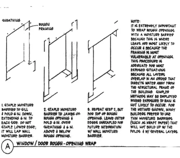
2.0 Is an Integral Nail-on Flange an Adequate Window Jamb Flashing?
Figure 2.1 shows the accepted shiplap or "weather-board" flashing sequence for a nail-on vinyl window. ASTM E2112-01 requires a nine (9) inch minimum jamb flashing be included in the detail
By definition, a flashing creates a drain
path - the course - under the influence of gravity - the force -to collect and
direct water to the exterior. An
adequate flashing is defined as a detail that in isolation, without the assistance of other details, creates a drain path that collects and directs water to the
exterior.
The chapter answers the question of whether an integral nail-on mounting
flange is by itself an adequate window
jamb flashing for a drainage/membrane type residential wall? If so, then the nine inch wide jamb flashing can be eliminated from Figure 2.1 and Figure 2.2 illustrates the modified flashing sequence for a nail-on window. If jamb flashing is required, then a series of follow up questions that include whether ASTM International's
recommendation are appropriate, what is an ideal window/wall waterproofing detail and conversely what is the primary weakness of existing window flashing details must be addressed. To answer these questions, a novel Fhfng Applied in We t rid Fashion) modeling and testing program has been
designed and implemented. This testing program was created because there is no
existing ASTM International test that
focuses only on the performance of the nail-on flange as a flashing element.
The set of existing ASTM International tests include relevant lab tests are:
Figure 2-2 flashing application without the jamb flashing
both lab tests and field tests. The 1) ASTM E283-91 (measure
air infiltration of the window unit);
2) ASTM E547-86 "Standard Test Method for Water Penetration of Exterior Windows, Curtain Walls, and Doors by Cyclic Static Air Pressure
Differential"(measures water penetration of the window or door unit); 3) ASTM E331-86 (measures
water penetration of the window or door unit) The field tests are:
1) ASTM El 105-86 "Standard Test Method for Field Determination of Water Penetration of Installed Exterior Windows, Curtain Walls, and Doors by
Uniform or Cyclic Static Air Pressure Difference" (this test measure the
performance of the installed unit);
2) AAMA 501.2: "Field Check of Metal Curtain Walls for Water Leakage" (a.k.a. AAMA 501.2 94: Field
Check of Metal Storefronts, Curtain Walls, and Sloped Glazing Systems for Water Leakage) (The procedure sprays a window unit with a 19mm (3/4") diameter hose fitted with a Type B-25,
These tests either focus on testing the performance of the un-installed window unit (the lab tests) or the performance of a complete window/wall assembly under a pressure differential (the field tests). Neither condition applies to the present question. What is needed in this case is a test that simulates the performance of a single detail as part of a construction system under a failure condition, not the performance of the entire window element or the performance of an "intact" window/wall assembly during a driving rain event.
2.1 Jamb Drip Test
Recalling a point made in chapter 1.0, for a water leak to occur in a wall, three conditions must coexist. At a particular location, there must be source of water, a force to move the water and a course for the water to follow. The Jamb Drip Test creates a situation where these three conditions co-exist.
In this test a measurable, verifiable amount of water is introduced in front of or behind the weather resistant barrier (WRB) at the junction between the window head nail-on fin and the jamb nail-on for a particular construction sequence. The subsequent steady state path taken by the water under the influence of gravity is recorded. Several construction
sequences are tested, and based on these observations the question is answered.
The Jamb Drip Test is empirical. Its operating premise is that once a source of water is deliberately introduced at the point of interest, the flow of water from this point is a
function of the relevant force and course created by the construction sequence in question. To determine if the nail-on fin is an adequate flashing, one has to understand how the nail-on flange performs not in isolation but as part of a construction system
created by the order in which the different elements were assembled (i.e. the construction sequence). The test is designed to provide this answer. Given the nature of what is trying to be accomplished, this type of test is referred to as a point of failure test.
Success or failure of the assembly in question is ultimately based on whether the introduced water is collected and directed to the outside along the window jamb edge. However, in addition to knowing whether water exits the wall assembly, the path taken by the water is also important. This last point will help determine the ideal window
nail-on fin jamb-flashing cnail-onfiguratinail-on.
Different window/wall assemblies are tested to determine how the nail-on flange performs as a flashing. To this end, the tests begin with the performance of the nail-on
fin in isolation and then progresses to the nail-on fin's performance in complete assemblies. When completed assemblies are tested, the choice of installing the WRB before or after the window as per ASTM E2112-01's Installation Procedure Selection Chart (Windows)' becomes a focus providing an order to the Drip Jamb Test sequence. For each complete assembly (i.e. an assembly that includes a window, WRB and siding), three siding options are evaluated:
1) a clear clapboard (see below for an explanation of why this type of siding was included in the tests);
2) cedar clapboard; and 3) vinyl siding.
As well, to include a drain plane type wall, a test on a furred out wall2 (that assumes the
WRB is installed prior to the window) will be done.
ASTM E2112-01 was used as a guide to select the material used for the WRB in each construction sequence. Housewrap (i.e. Tyvek) was used as the WRB, when the WRB was applied before the window. When the WRB was applied after the window, asphalt felt was used as the WRB. In the case of the furred out wall, ASTM E2112-01 provides no guidance on the recommended WRB. Neither is there an industry consensus for this type of wall construction. The author has experience with housewrap in this type of construction, so it was used in the present test.
Before the actual test procedure is described, information about the construction of the base window/wall assembly, the procedure used to introduce a measurable, verifiable and repeatable amount of water for each test and the visual techniques employed in the tests are discussed.
2 A furred out wall is one where a 1" x 3" piece of strapping is installed vertically over the housewrap at 16" on center. The siding is then nailed to the strapping. This detail creates a 16" wide drainage plane at 3" increments across the wall surface.
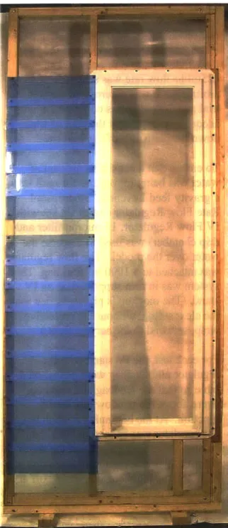
2.1.1 The Construction of the Base Window /Wall Assembly
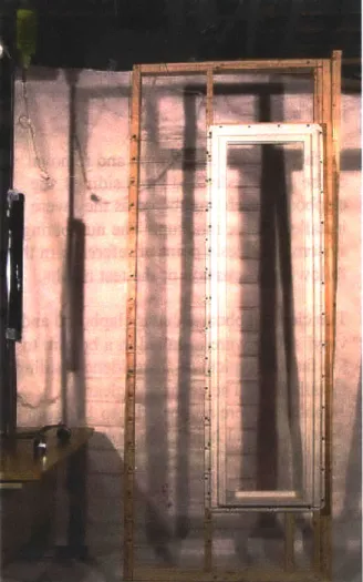
In the Jamb Drip Test, the ability to photograph results is paramount. Equally important, is consistency between results. As a result, a single or base window/wall assembly mockup is used for all tests.
The base window-wall mockup is made from 2"x 3" dimensional limber and
sheathed with a 33 2" x 90" % thick acrylic
sheet. It is framed using conventional platform framing techniques.
The mockup's outside dimensions are 35
5/8" x 91 %". The acrylic sheet's outside dimensions are 33 /2" x 90". An 18 %" x 64
/2" cut is made in one side of the acrylic sheet (For this explanation, this side will be considered the right side of the sheet). The
T resulting form of the acrylic sheet resembles
a C. The overall dimensions of this C
shaped sheet have an 18 %" x 64 2" inside
cut thirteen inches from the sheet's top and bottom, and fifteen inches from its left side. The " acrylic sheet is installed flush to the wood frame's left side. This results in the need to insert thirteen- inch support blocks against the acrylic sheet's right side. To compensate for the sheet's
a
%" x 1 %""", strip is fastened to the mockup's right hand side vertical outside stud. The resulting construction creates a 19" x 64 " rough opening. The nail-on window is introduced into this opening and the mockup braced in a vertical position.As per ASTM E2112-01, a 3/8" bedding joint (prior to compression) was installed between the nail-on flange and the acrylic sheet and/or WRB for each test. Once compressed the bedding joint "bleeds out" along the edge of the flange.
2.1.1.1 Description of the Cedar Clapboard and Vinyl Siding
Each piece of cedar clapboard was 5 %/" high x 14 %" long. Cedar clapboard has a tapering profile widening from 1/8" at its top edge to 3/8, at its bottom edge. Finished
(one side smooth) Western Red cedar clapboards were used in the present set of tests.
Figure 2-4 cedar siding pi
Each piece of vinyl siding was 9 %" high x 14 %" long. The vinyl was made from PVC. The vinyl siding used in the experiments simulated horizontal lap siding with two siding courses per panel. The top edge of the vinyl siding had a single thickness nail hem. The bottom or locking edge had a post- formed edge.
Figure 2-7 vinyl siding side profile Figure 2-6 vinyl siding profile
2.1.1.2 The Design of a Clear Clapboard
A clear clapboard was designed so that the flow of water behind a typical clapboard
could be photographed. The clear clapboard was designed to have a similar wall side profile as a cedar shingle.
To create this profile, a clear shingle was constructed from a 14 %" x 5 3/8" sheet of 1/8"
thick acrylic. To provide the necessary offset, a " x " clear acrylic strip was glued in
place four inches from the bottom of the sheet. This geometry resulted in the %" x "
strip being one inch from the sheet's top edge. At the point of the " x ' strip, the total
thickness of the clear shingle was 3/.
The clear shingle has a blue tint in this picture because the protective film was not removed at this point.
1/4"x 1/4" offset
4F1
Figure 2-9 profile of the clear clapboard
2.1.1.3 Siding Options
Using the base window/wall assembly, the WRB, furring strip and siding options were added as required. Each siding option was installed along the left side of the mockup and water was introduced at the left junction of the window's head and jamb nail-on flange.
To facilitate the installation and removal of the clear, cedar and vinyl sidings, the clapboards were numbered as they were installed on the mockup. The numbering system provides a point of reference in the following discussion of the test results. The clear clapboard, cedar clapboard and vinyl siding were installed in a bottom to top fashion typical of all residential siding installations. The cedar and clear
clapboards were numbered 1 to 18 given their individual heights. Clapboard 1 was installed first. Clapboard 18 was installed last. The vinyl sidings were numbered 1 to 10 given their individual heights.
Vinyl siding 1 was installed first and vinyl
siding piece 10 (a half piece) was installed last.
Each sheet was installed with the sheet's top edge facing upwards and the " x "
strip facing outwards (away from the sheathing). To create the "four inch to weather" clapboard pattern, a clear sheet
was installed against the acrylic sheathing and the next sheet was installed above this sheet with its edge flush to the bottom
Figure 2-10 installation of the clear clapboards on edge of the " x " strip of the previously
the mockup installed sheet.
In this photo, the protective wrap was not removed from the clear sheets. Blue was the typical color of the protective wrap with the exception of the first and twelfth sheets whose protective wrap was colored light green.
2.1.2 The Procedure Used to Introduce a Measured Amount of Water at the Junction of the Window's Head Nail-on Flange and the Jamb Nail-on Flange
For each test, water was introduced at a
rate of 125 ml/hr for a ten-minute period at the junction of the window head and the window jamb (see bebw). The 125ml/hr flow rate was selected arbitrarily. It was determined through trial and error that this combination was adequate to document the path of water down the jamb side of the window. To ensure that a consistent amount of water was being introduced for each test,
a gravity feed Leventon3 20 drops/ml
Rate Flow Regulator (Adult IV Set with IV Flow Regulator, 15 micron filter and drip chamber) was used to disperse the water over the model. The flow regulator was attached to a 1000 ml feed bag. This system was in turn supported on an IV stand. (The mockup is photographed with the clear siding, without the protective wrap, screwed to the acrylic sheet.) For each test, the IV stand with the regulator and feedbag were placed on a table so that the feedbag and regulator
Figure 2-11 Jamb Drip Test Set up were above the window head/jamb junction. At the beginning of each test,
the regulator was opened to the 125ml/hr setting, the time recorded and the water
allowed to drip for ten minutes. After ten minutes, the regulator was turned off and the results photographed.
3 Leventon, SA
Poligono CAN Sunyer, 11 08740 Sant Andreu de la Barca Barcelona, Spain
2.1.2.1 Water Introduction Points
Water was introduced directly over the nail-on flange and immediately next to the nail-on flange. The water
introduction point locations are consistent for each test.
Figure 2-12 water introduction point directly over the nail-on flange
Figure 2-13 water introduction
point next to the nail-on flange (front view)
Figure 2-14 water introduction
2.1.3 Recording the Path Taken by the Water as it Travels Down the Window Jamb under the Influence of Gravity
Each test was photographed on the MIT campus, in the Heat Transfer Lab. A space was sheeted off using Tyvek housewrap as a backdrop and photos were taken with an
Olympus C-740 digital camera. The images were saved as JPEG files.
Post photo manipulation was done using Adobe Photoshop 6.0 and was limited to
cropping, and altering the JPEG image's color brightness and contrast manipulation. The background shadows cast by the mockup onto the Tyvek sheet was left in the image. For
document consistency, all imags were sized with a 3" width and printed at a resolution of 150 pixels/inch for publication.
Since the objective was to record the water path, images were photographed under both white light and black light. When photographing in white light, 3 120V/300W
LowelTOTA-light lamps were used. When photographing in black light four 48" black lights were used. Two black lights were connected to a 48" florescent light tray. The trays were positioned around the model to illuminate the water path as required.
So that the water path would illuminate under black light, it was dyed with a 40%
concentrated aqueous sodium fluoroscein4. The dye solution was mixed to a ratio of 0.5
ml sodium fluoroscein to 1000 ml water. Once mixed, 1000 ml of the dye solution was poured into the feedbag. This mixture was then dripped over the model via the drip
regulator. While the dyed water could be seen under white light, it showed best under black light.
Figure 2-15 fluoroscein dye Figure 2-16 fluoroscein dye illuminate d under black light illuminated under white light
4 The author contacted the seller of the Fluoroscein dye, Mr. Daniel K. Afrides who informed him that the dye was not a biohazard and could be used safely in this study.
2.1.4 Drip Jamb Test Procedure Recap
Each Drip Jamb Test was completed under an identical three-step procedure: 1. construct the desired WRB/window/siding option on the base window/ wall
assembly;
2. introduce water at a rate of 125 ml/hr for ten minutes at the junction between the window head nail-on fin and the jamb nail-on fin via the feedbag/flow regulator set up; and
3. photograph the steady state path taken by the water after ten minutes using white or black light.
2.2. Water Drainage Paths
The following series of tests provide information about the in-service performance of the nail-on fin as a flashing element in isolation - when it is the only element attached to the base mockup and when it is part of a system of assembled components. A description of each test is included. This body of information is then considered as a whole to answer the question of whether the nail-on mounting flange alone is an adequate window jamb flashing for a drainage/membrane type residential wall?
The first set of Drip Jamb Tests focused on the in-service performance of the nail-on fin as a flashing element in isolation of the other wall elements. This set of six tests is collectively termed the isolation tests. Tests were completed for the clear clapboard, the cedar clapboard and the vinyl siding. Water was introduced directly over, and next to the nail-on fin.
isolation tests
Test 1: no WRB or clapboard, water introduced directly over the nail-on fin Test 2: no WRB, clear clapboard, water introduced directly over the nail-on fin Test 3: no WRB, cedar clapboard, water introduced directly over the nail-on fin Test 4: no WRB, cedar clapboard, water introduced next to the nail-on fin Test 5: no WRB, vinyl siding, water introduced directly over the nail-on fin Test 6: no WRB, vinyl siding, water introduced next to the nail-on fin
2.2.1 Test 1: no WRB or Clapboard, Water Introduced Over the Nail-on Fin
The water path that developed began as a continuous, single file line of vertical drips. This pattern then dispersed or spread into a fan shape one third of the way down the nail-on fin. This fan shape was made up of five separate drip lines. The five separate lines moved parallel to each other up to the mid-point of the nail-on fin.
At the mid point, five separate lines re-joined into one line that traveled along the inside edge of
the window's
j
channel to thebase of the nail-on fin. At this point, the water traveled onto the acrylic sheet down to the base of the mockup at which point it dripped onto the floor below.
Figure 2-17 Test 1 drip Figure 2-18 Test 1 drip This pattern developed once
pattern at the window head pattern at the window the test started and continued
sill until the test stopped.
This drip pattern illustrates how water travels down the window jamb when the window assembly is separated from the WRB and siding. It shows that the mounting flange acts as a jamb flashing. If water was introduced at the window head it would travel along the length of the window over the mounting flange and out the assembly via the sill flashing. This test documents that the mounting flange does act as a jamb flashing by design.
2.2.2 Test 2: no WRB, Clear Clapboard, Water Introduced Over the Nail-on Fin
Initially, a drip pattern was noted as water traveled down the first two clapboards. The water left the tube in plane with clapboard
18. It then free fell to the top
edge of clapboard 17. This pattern repeated itself between clapboards 17 and 16.
At clapboard 16, water collected, began to pool at the " x "
strip. The water eventually exited between clapboard 17 and
16 to the exterior. The exit point
of the water was not in- line with the insertion point, but within an inch to the left of the insertion point.
At this point, water sprayed over the exterior of the window/wall
Figure 2-19 Test 2 drip Figure 2-20 Test 2 drip assembly dripping on both the
pattern at the window head pattern (side view) clear clapboards and the window
frame. This water path was established within two minutes of starting the test and continued over the next eight minutes until the test was concluded.
Within the limit of how the clear clapboard approximates the cedar clapboard, this test is an acceptable visualization of how water travels between the mounting flange and the clapboard. In this test, water did not travel down the entire length of the mounting flange, but exited the assembly within two clapboards. From the test, it was observed that water dripped from the top to the bottom of the first clapboard. It then migrated between the interface of the top clapboard and the one immediately below it exiting the assembly via this lap joint. This test demonstrates how the clapboard system directs incidental water to the exterior and by extension, how the clapboard system acts as a contained drain plane.
2.2.3 Test 3: no WRB, Cedar Clapboard, Water Introduced Over the Nail-on Fin
A similar water path was observed with the cedar siding.
Water traveled behind clapboard 18 and then exited between clapboards 18 and 17. In this case, (it is assumed), water did not travel along the nail-on fin, but free fell directly to the intersection of clapboards 18 and 17 where it was diverted to the exterior due to the clapboard's lap design.
This test verifies the results and conclusions of Test 2. The noted exterior water drip pattern verifies that when water is present between the window's mounting flange and the
clapboard system it will exit the building due to the design of the clapboard system.
2.2.4 Test 4: no WRB, Cedar Clapboard, Water Introduced Next to the Nail-on Fin Water dripped along the acrylic sheet down the entire length of the window jamb. Within five minutes of the test, water stains begin to appear on cedar clapboard at the point where the nail-on fin touched the clapboard. The staining was most noticeable in clapboard 17.
This suggests that water was being drawn to the nail-on fin from the acrylic sheathing. At this point it was in direct contact with the porous cedar. Capillary action then drew the water into the individual cedar clapboards resulting in the observed staining pattern.
This test points to the problem associated with water traveling between the mounting flange and the cedar clapboard. If the cedar is not sealed before it is installed in the wall, it will get wet. Given the location, it may not be able to dry out. This could lead to paint not adhering to the clapboard to premature failure due to rot.
The value of this test was in recognizing the "cost" associated the siding acting as a drain plane. The cedar Figure 2-22 Test 4 water clapboards should be sealed (i.e. back primed) before they are
stains along the window installed on the wall.
2.2.5 Test 5: no WRB, Vinyl Siding, Water Introduced Over the Nail-on Fin
Water dripped down the length of
the nail-on fin onto the acrylic sheet and then puddled on the floor. This straight-line path developed within five minutes of the test and continued until the test was terminated.
The test illustrates how water
il-4n fin travels along the window jamb
when clad with vinyl siding. Unlike the clear and cedar clapboard pattern, water did not exit the assembly but traveled between the vinyl mounting flange and the vinyl siding. In this case there is no concern with rot given the nature of the materials involved.
Figure 2-23 Test 5 drip pattern
Figure 2-24 Test 5 drip pattern at the window sill
2.2.6 Test 6: no WRB, Vinyl Siding, Water Introduced Next to the Nail-on Fin Water dripped onto clapboard 9's nailing band from the water
introduction tube. The water then dripped from this nail band onto clapboard 8's nail band. The pattern continued with the water
dripping onto each successive nail band. When viewed as a whole, the water drip pattern looked like a dot pattern with each dot equally spaced from its neighbors.
While some water splattered onto the acrylic sheet in the vicinity of clapboard 9, this splatter appeared to be incidertal to the primary
drip pattern described above.
Figure 2-25 Test 6 drip Figure 2-26 Test 6 dot pattern pattern
The concern with this test is whether water would travel over an oriented strand board or plywood sheet as it does over the acrylic. Assuming that water would travel over new oriented strand board or plywood as it did in this test, the significance of this test is in demonstrating the existence of a drain plane between the acrylic sheet and the vinyl siding. Water, under the influence of gravity traveled along the mounting flange and exited the assembly.
The significance of Tests 1-6 was in demonstrating that the mounting flange collects and directs water to the exterior. It completes this function both in isolation and whe n it is combined with clear clapboard, cedar clapboard or vinyl siding. The tests illustrated the presence of a continuous drain plane along the length of the mounting flange. This mounting flange was present along the length of the mounting flange as well as immediately next to it.
The second set of tests simulated a window/wall assembly with the WRB (Tyvek
Housewrap) installed prior to the window. This set of four tests is collectively termed the WRB- window tests. Similar to the isolation tests completed above, tests were done for clear clapboard, cedar clapboard and a vinyl siding. Since these are visual tests, to establish a benchmark, water was inserted in front of and behind the WRB in the case of the clear clapboard. Water was inserted behind the WRB, next to the nail-on fin in the case of the cedar clapboard and vinyl siding.
In these tests, a sill- flashing element was applied to the WRB as per ASTM E2112-01. Test 7: WRB, clear clapboard, water introduced in front of the WRB directly over the nail-on fin
Test 8: WRB, clear clapboard, water introduced behind the WRB next to the nail-on fin Test 9: WRB, cedar clapboard, water introduced behind the WRB next to the nail-on fin Test 10: WRB, vinyl siding, water introduced behind the WRB next to the nail-on fin
2.2.7 Test 7: WRB, Clear Clapboard, Water Introduced in Front of the WRB Over the Nail-on Fin
Figure 2-27 Test 7 drip Figure 2-28 Test 7 drip pattern at the window head pattern along the entire
length of the window jamb
The observed water drip pattern was similar to the one noted in Test 2. The WRB is behind the nail-on fin, and with the water introduced in front of the nail-on fin; the WRB does not influence the water flow along the jamb. For the purposes of the study, the above water pattern (to a first order) is assumed to take place behind cedar and vinyl sidings. This test illustrates how the water drip pattern is affected by the presence of the weather resistant barrier. Water travels over the mounting flange, but once it comes in contact with the sill flashing it is not directed to the exterior but deviates
horizontally within the wall assembly.