Publisher’s version / Version de l'éditeur:
International Journal of Contemporary ENERGY, 2, 2, 2016
READ THESE TERMS AND CONDITIONS CAREFULLY BEFORE USING THIS WEBSITE. https://nrc-publications.canada.ca/eng/copyright
Vous avez des questions? Nous pouvons vous aider. Pour communiquer directement avec un auteur, consultez la première page de la revue dans laquelle son article a été publié afin de trouver ses coordonnées. Si vous n’arrivez pas à les repérer, communiquez avec nous à [email protected].
Questions? Contact the NRC Publications Archive team at
[email protected]. If you wish to email the authors directly, please see the first page of the publication for their contact information.
Archives des publications du CNRC
This publication could be one of several versions: author’s original, accepted manuscript or the publisher’s version. / La version de cette publication peut être l’une des suivantes : la version prépublication de l’auteur, la version acceptée du manuscrit ou la version de l’éditeur.
For the publisher’s version, please access the DOI link below./ Pour consulter la version de l’éditeur, utilisez le lien DOI ci-dessous.
https://doi.org/10.14621/ce.20160202
Access and use of this website and the material on it are subject to the Terms and Conditions set forth at
A fuel saving way in aerospace engineering based on morphing wing
technology: a new multidisciplinary experimental model
Kammegne, Michel Joel Tchatchueng; Botez, Ruxandra Mihaela; Grigorie,
Teodor Lucian; Manou, Mahmoud; Mebarki, Youssef
https://publications-cnrc.canada.ca/fra/droits
L’accès à ce site Web et l’utilisation de son contenu sont assujettis aux conditions présentées dans le site LISEZ CES CONDITIONS ATTENTIVEMENT AVANT D’UTILISER CE SITE WEB.
NRC Publications Record / Notice d'Archives des publications de CNRC:
https://nrc-publications.canada.ca/eng/view/object/?id=ac894349-03de-419c-882a-89bc9b664601 https://publications-cnrc.canada.ca/fra/voir/objet/?id=ac894349-03de-419c-882a-89bc9b664601___________________________________________________________________________________________________________ DOI: 10.14621/ce.20160202
A Fuel Saving Way in Aerospace Engineering based on Morphing Wing
Technology – A New Multidisciplinary Experimental Model
Michel Joel Tchatchueng Kammegne
1, Ruxandra Mihaela Botez
1*, Teodor Lucian Grigorie
1,
Mahmoud Mamou
2, Youssef Mebarki
21École de Technologie Supérieure
1100 Notre Dame West, H3C 1K3, Montreal, Quebec, Canada; [email protected] 2National Research Council Canada
1200 Montréal Road, K1A 0R6, Ottawa, Ontario, Canada
Abstract
The research presented in this present paper was done within the framework of the international CRIAQ MDO505 Morphing Wing project, developed as a collaborative research project between academia, research centres and industry partners. The work exposed in the paper is related to the development of an experimental morphing wing model and its performance evaluation by using some wind tunnel tests. This collaborative research aimed at the drag reduction over a wing by morphing it, conducting in this way at fuel savings and low emissions. The association between the drag reduction and wing morphing comes from the fact that if the wing airfoil shape is changed in a specific way then the laminar to turbulent flow transition point position can be moved toward its trailing edge. The model designed, fabricated and tested during our project is based on the dimensions of a full scale wing tip structure, equipped with a morphable flexible upper surface made from composite materials and deformed by using four miniature electrical actuators, with an array of 32 Kulite pressure sensors to monitor the air flow behaviour over the upper surface, and with an aileron also electrical actuated.
The first specific objective for our research team in this project was to develop a new morphing mechanism for the wing by using miniature electrical actuators; these actuators should deform the upper wing surface, so that the laminar-to-turbulent transition point moves closer to the wing trailing edge reducing in this way the drag force as a function of flow condition by changing the wing shape. The flow conditions were univocally defined by mean of Mach numbers, airspeeds, angles of attack and aileron deflection angles. The second specific objective was to develop a control system for the morphing actuators to obtain the desired morphed shape of the wing for each studied flow case, while the third specific objective was to develop a monitoring system able to detect and visualize the airflow characteristics using pressure sensors installed on the upper surface of the morphing wing, evaluating in this way the gains brought by the proposed architecture. During the paper sections are successively exposed the project description, the morphing wing model instrumentation and the mechanisms used to control it. Finally, a wind tunnel aerodynamic results analysis is performed, discussing the extension of the laminar region of the flow over the wing by using the morphing wing technology.
1.
Introduction
Regarded as one of the promising technologies in terms of saving fuel and limit emissions in the aerospace industry, the morphing technology has undergone various ways of implementation, among which highlights the morphing wing. The advantages of this technology have been proven by developing and testing numerous experimental models both in Industrial laboratories and in the laboratories of universities and research institutes. The researches were carried out both by local projects involving a single institution, and through collaborative projects with large industrial impact, involving entities from all sectors of aerospace field, and integrating human resources and expertise from academia, research and testing, and industry. The mechanism that has been identified morphing wing technology impact on fuel consumption was to improve the aerodynamic performance of the vehicle by reducing the drag. Therefore, technical solutions were sought to change the wing shape as a function of the flight conditions so as to obtain an extension of the laminar flow on its surface, extension equivalent with a decrease in drag force [1]-[20].
A research team from the Royal Melbourne Institute of Technology, Australia, developed and tested in the wind tunnel a wing model morphed by using SMA actuators; a significant change in the lift to drag ratio was detected when the wing was morphed [1]. In another study was performed the aerodynamic design optimisation of a micro air vehicle wing to obtain the optimal anti-symmetric wing twist distribution, with the aims to produce minimum induced drag and to achieve a better roll response [2]. A multiloop controller for the aeroelastic morphing unmanned aerial vehicle concept was formulated by a collaborative research team from USA and Spain; the approach successfully enabled in-flight transformation between vehicle states in less than
Keywords: Energy save; Drag reduction; Morphing
wing; Experimental testing; Wind tunnel; IR analysis
Article history: Received: 09 April 2016
Revised: 30 October 2016
___________________________________________________________________________________________________________ one minute, while maintaining the overall vehicle
stability and control [3]. At Virginia Tech, USA, the using of macro fiber composite actuators in morphing unmanned vehicles was tested; an important improvement of the lift to drag ratio was experimented as a consequence of wing morphing [4]-[6]. A concept of hexagonal chiral honeycomb structure for adaptive wing box configurations was proposed at University of Sheffield, UK [7]. A collaborative research between Portugal and Canada used a multidisciplinary design optimization tool, coupling an aerodynamic shape optimization code with a structural morphing model to obtain a set of optimal wing shapes for minimum drag at different flight speeds [8]. The optimum drag reduction as a consequence of the airfoil morphing was also investigated at University of Tokyo, Japan [9]. From another perspective of the morphing technologies, a topology optimization approach for determining the distribution of structural properties and actuators to design a morphing wing that is capable of achieving multiple target shapes was realized at University of Ohio, USA [10]. Several experiments on flow control using an adaptive circular arc airfoil were also performed at University ok Kentuky, USA [11]. At RTM Nagpur University, India, a variable camber wing model using multi section ribs was designed and tested [12]. From the aerodynamic optimization perspective, a very interesting study has been realised at Purdue University, USA, where the energy was used as objective in the optimization process of a morphing airfoil [13]. Based on the fact that dynamic loads are essential for the design of any morphing-wing aircraft, several studies were conducted at University of Texas at Arlington, USA, to develop methodologies suitable for numerical calculation of the dynamic loads for morphing wing aircraft [14], [15]. At Cranfield University, UK, has been realised an investigation into the concept and optimal design of a lightweight seamless aeroelastic wing (SAW) structure for small air vehicles; two innovative design features have been created in the SAW trailing edge
section: an open sliding trailing edge and a curved beam and disc actuation mechanism [16]. A collaborative research team realized an experimental analysis of low speed flow over an adaptive airfoil with oscillating camber; the experimental results were compared to a series of CFD simulations in order to evaluate, among others, the effectiveness of the oscillating camber as a flow control mechanism [17]. At Middle East Technical University, Ankara, Turkey, was performed the modelling and aeroelastic analysis of an adaptive camber wing subjected to low-speed subsonic flow; the camber variation was controlled at six spanwise stations, the actuation force magnitudes being determined iteratively using linearized influence coefficients [18]. Researchers from University of Toronto, Canada, developed an aerodynamic optimization algorithm and used it to assess an adaptive airfoil concept for drag reduction at transonic speeds [19]. A review of the morphing aircraft, with specific focus on modelling and flight control of large-scale planform altering flight vehicles, proceeded to demonstrate in a fundamental manner that, although design methods for rigid aircraft have become highly developed, the consideration of morphing necessitates further investigation into the typically disparate fields of dynamic modelling, aerodynamic theory, and flight control theory [20].
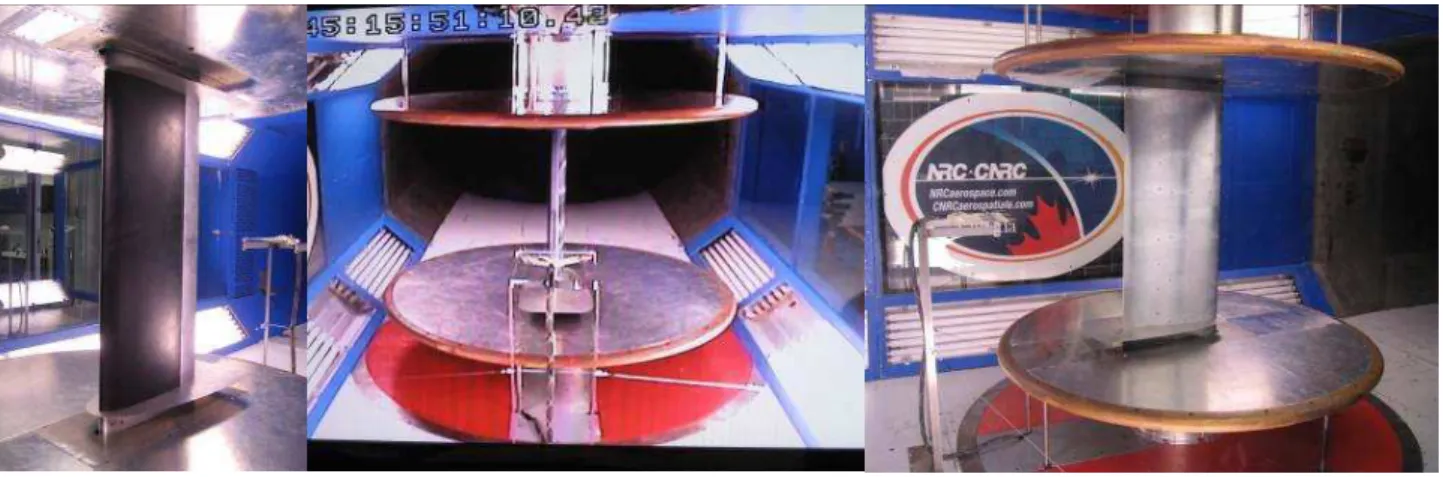
In order to develop such green aircraft technologies, our research team from Research Laboratory in Active Controls, Avionics and AeroServoElasticity (LARCASE) at École de Technologie Supérieure in Montréal, Canada, developed some morphing wing projects. In a first project, called CRIAQ 7.1 (Consortium for Research and Innovation in Aerospace in Quebec), a morphing wing experimental model was realized at LARCASE laboratory (Figure 1). During this project, new methodologies to morph a wing by using smart actuators and various control techniques, starting from open loop control architectures to closed loop real time optimization of
___________________________________________________________________________________________________________ Figure 2. Morphing wing model in Price- Païdoussis subsonic wind tunnel
the morphing wing controller, were developed and experimentally validated [21]-[40]. In the open loop architecture, the research team proposed and validated few control techniques for the morphing wing actuation system, based on classical or intelligent methodologies. On the other way, simulations and experimental methods pertinent to transition location detection has been presented [35], [36], [40].
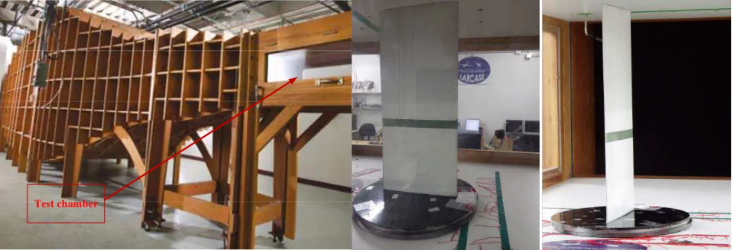
In another morphing wing project developed by our team, a wing prototype with an integrated actuation mechanism was fabricated and tested at Ecole de Technologie Superieure in Montreal (Figure 2). In this project instead of using adaptive materials such as SMA and piezoceramic actuators, a new approach using electrical actuators coupled to two actuation lines was tested. A control system was designed for the actuation system to obtain the optimized profile for each considered flight case. The actuator position was controlled using a cascade control algorithm. The aerodynamic results obtained in our Price-Paidoussis wind tunnel were compared with the numerical results predicted by XFoil software in the optimization phase [41]-[44].
The here exposed work refers to the morphing wing studies of the LARCASE team related to a new CRIAQ project, Multi-Disciplinary Optimization 505 (MDO 505), aiming at fuel consumption optimization by applying morphing wing technology to a real aircraft wing. The project, realized at École de Technologie Supérieure in Montréal, Canada, is the result of a collaborative multidisciplinary research team, integrating human resource coming from partners in Canada and Europe. The industrial partners in Canada are Bombardier Aerospace and Thales, while in Europe is Alenia Aerospace. The universities and research institutes participating in Canada are École de Technologie Supérieure (ETS), École Polytechnique and Institute of Aerospace research at National Research Council of
Canada (IAR-NRC). Universities and research centres participating from Europe are Frederico II Naples University and Italian Aerospace Research Center (CIRA) [45]-[46].
2.
Morphing wing project
In this research project, a wing-aileron prototype was designed, tested and validated using win tunnel tests at National Research Council Canada (IAR-NRC). The multidisciplinary research team of the project was divided into three sub-teams covering aerodynamic, structural, and control fields. The main aims of the project were to reduce the operating costs for the new generation of aircraft through in-flight fuel economy, and also to improve aircraft performances, expand its flight envelope, replace conventional control surfaces, reduce drag to improve range and reduce vibrations and flutter risk [47].
The first specific objective for our research team in this project was to develop a new morphing mechanism using miniature electrical actuators for a full-scaled portion of the wing of a real aircraft equipped with an aileron. The actuators deform the upper wing surface, made of a flexible skin, so that the laminar-to-turbulent transition point moves closer to the wing trailing edge reducing in this way the drag force as a function of flow condition by changing the wing shape. The flow conditions were univocally defined by mean of Mach numbers, airspeeds, angles of attack and aileron deflection angles. The second specific objective was to develop a control system for the morphing actuators to obtain the desired morphed shape of the wing for each studied flow case, while the third specific objective was to develop a monitoring system able to detect and visualize the airflow characteristics using pressure sensors installed on the upper surface of the morphing wing.
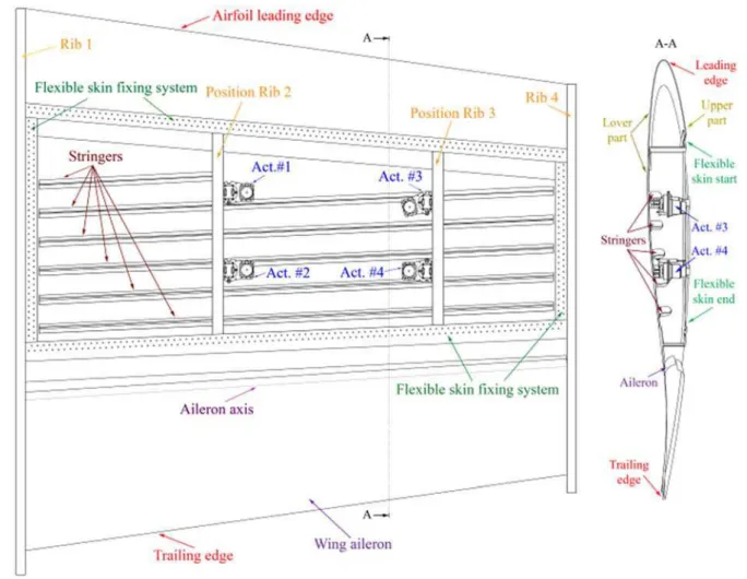
___________________________________________________________________________________________________________ Figure 3. Wing structure and actuations lines positions
___________________________________________________________________________________________________________ The used experimental wing segment was with a
maximum chord of 1.5 m, and a minimum one of 1.08 m, and has three distinct parts: 1) a metal part, which has the structure as in the original aircraft wing; 2) a morphing part, consisting of a flexible skin installed on the upper surface of the wing; and 3) an actuated aileron (Figure 3 [47], [48]. The first part structure includes four ribs, two at the ends (Rib 1 and Rib 4), and two inside (Rib 2 and Rib 3) having also the role to support the actuators. The morphing skin, made from composite materials, allowing the wing shape changing, was positioned on the upper side of the wing between 20% and 65% of the wing chord (Figure 4). To morph the flexible skin were used four similar actuators disposed on two actuation lines positioned at 37% and 75% of the wing’s span. The actuators were positioned at 32% and 48% of the local wing chord on each of the two actuation lines. The actuators were fixed on the wing ribs and the top were attached to the flexible skin with screws. The actuation mechanism architecture supposed the direct actuation of the flexible skin by the four actuators. This architecture, with estimated forces of over 1300 N per actuator, correlated with the small space inside the morphed wing (the wing thickness varies between 10 cm and 20 cm), and with small maximum displacement (maximum 5 mm) imposed serious size/power constraints to the actuators. To meet both the requirements of size and power, the actuator was designed in-house by using some components acquired on the market such as the miniature brushless direct current (BLDC) motor [47].
To establish the optimum shape of the wing for a specific flow condition an optimization phase was performed by the aerodynamic team of the project. The optimization procedure was applied for several combinations of Mach numbers (M), angles of attack (α) and aileron deflection angles (δ). An in-house developed genetic algorithm was used in the iterative optimization process, with the objective to search the optimum shapes for an airfoil through local thickness changes to improve the upper surface flow. The optimization started from a reference airfoil shape, and was a complex one, needing several interactions between the genetic algorithm parameters, objective function, aerodynamic solver and shape reconstruction using spline interpolation [48]. For each optimized airfoil resulted four vertical displacements corresponding to the positions of the four actuators. Actually, the optimization gave the displacement values for one pair of actuators situated at 37% of the wing span, while the displacements for the second pair of actuators were calculated as a linear dependence [48]. All optimization results were stored in a database in order to be used as reference vertical displacements for the control system.
The aerodynamic performance of the morphing wing model was tested in wind tunnel at Institute for
Aerospace Research at the National Research Council Canada (IAR-NRC) in Ottawa for ninety seven flow cases. The tested flow cases were obtained as combinations of nineteen values for the angle of attack (varied from -3 degree to +3 degree), three values for the Mach number (0.15, 0.2, 0.25) and thirteen values for the aileron deflection angle (varied between -6 degrees an +6 degrees). For each case, the flexible upper surface of the wing was actuated in order to obtain the four optimized values of the vertical displacements corresponding to the four actuation points and stored in the aerodynamic database. The evaluation of the laminar-to-turbulent transition location was performed by using the pressure data obtained from 32 high precision Kulite piezoelectric-type sensors placed on the flexible skin on two closes chord lines [46]-[48].
3.
Instrumentation of the experimental model
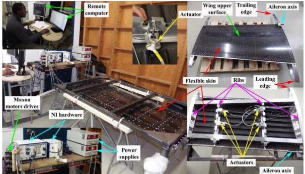
For the four morphing actuators was developed a control system able to control theirs linear positions. Actually, the control system included four similar controllers software implemented, able to modify the actuators linear positions until the real displacements of the morphing skin in the four actuation points equalled the desired displacements of the optimized airfoil resulted for a flow case. The feedback signals containing the actuators positions are provided by four Linear Variable Differential Transformers (LVDT). From the point of view of the control system were developed and tested various controllers, based on classical or intelligent techniques. The controllers were preliminary tested in the lab conditions, in the absence of the airflow, together with the associated software and hardware components included in the experimental model (Figure 5) [47].
The experimental model instrumentation was developed around a National Instrument equipment and included a NI PXIe-1078, 9-Slot 3U PXI Express Chassis, a NI PXIe-8135 embedded controller, four NI PXIe-4330 Data Acquisition Cards with Integrated Signal Conditioning for Bridge-Based Measurements, a NI PXI-8531, 1-Port CANopen Interface, a NI PXIe-6356 Simultaneous X Series Data Acquisition Card, a SCXI-1000 rugged, low-noise chassis that can hold up to four SCXI modules, a NI SCXI-1540 8-Channel LVDT Input Module, a NI SCXI-1315, and two Programmable power supplies Aim-TTi CPX400DP.
The next test of the experimental model was in the wind tunnel (Figure 6), the pressure signals being logged in parallel while the shape of the airfoil changed. A Graphical User Interface (GUI) was developed for the control system and for the data acquisition system. Simultaneously with the control system characteristics monitoring, the user visualized on a parallel screen the real time Fast Fourier Transforms (FFT) associated to the
___________________________________________________________________________________________________________ Figure 5. Bench test at École de Technologie Supérieure in Montréal
Figure 6. Wind tunnel testing of the experimental model
32 Kulite pressure sensors equipping the upper surface flexible skin. As a secondary method to evaluate the transition point position over the entire wing model surface for each tested flow case the infra-red (IR) thermography was used. In this way, visualizations with a Jenoptik Variocam camera were performed to measure the surface temperatures [49].
4.
Wind tunnel experimental results
To evaluate the aerodynamic gain of the morphing wing technology on the experimental model, the recorded pressure data during the wind tunnel tests were post processed in order to obtain the pressure coefficient distribution curve and the spectral repartition of the pressure. The transition region determined by the flow separation and characterized by the amplification of the
Tollmien-Schlichting waves was captured by the Kulite pressure sensors. The same aerodynamic gain was also evaluated by using the infra-red thermography technique. The pressure data were recorded at 20 kHz rate, for both un-morphed and morphed airfoils in ninety-seven flow cases, and were analysed using Fast Fourier Transforms (FFT) decomposition to detect the magnitude of the noise in the surface air flow. Subsequently, the data were high pass filtered at 1 kHz and processed by calculating the standard deviation (STD) of the signal to obtain a plot diagram of the pressure fluctuations in the flow boundary layer. Ninety seven flight cases were tested in the wind tunnel, obtained as combinations between nineteen values for the angles of attack (between - 3deg. and +3 deg.), three values for the Mach numbers (between 0.15 and 0.25), and thirteen for the aileron deflection angles (between - 6deg. and +6 deg.).
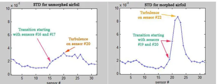
___________________________________________________________________________________________________________ Figure 7. STD of the pressure data acquired for Mach=0.15, α=-2˚, δ=-2˚ flow case
___________________________________________________________________________________________________________
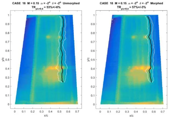
Figure 9. IR visualisation for Mach=0.15, α=-2˚, δ=-2˚ flow case
For the flow case associated to Mach=0.15, α=-2˚, δ=-2˚, Figure 7 presents the STDs of the acquired pressure data both for un-morphed and morphed airfoils. It results that the transition for un-morphed airfoil begins on the pressure sensor #16 (placed at 50.79% of the wing chord), while for morphed airfoil it begins on the sensor #19 (placed at 53.45% of the chord). On the other way, the maximum value of the STD for un-morphed airfoil was associated with the sensor #20 (placed at 54.60% of the chord), while for morphed airfoil was associated with the sensor #22 (placed at 56.87% of the chord). In the same flow case, the FFT plots for the two airfoils (un-morphed and (un-morphed) are shown in Figure 8. The FFT associated to the un-morphed airfoil shows that the curve corresponding to the sensor #17 is easiest detached indicating the transition beginning. A more visible detachment appears at the level of the sensors #18 and #19, producing the transition to the upper FFT curves package. For the morphed airfoil, the FFT characteristics show that the transition begin on the sensor #20, the maximum influenced FFT curves corresponding to the sensors #21 to #23. As a consequence, the FFT and STD based conclusions are similar for this flow case, the laminar region being extended with over 3% of the chord in the Kulite sensors section.
The infra-red thermography visualizations (from 0% to 70% of the chord) of the extrados for this flow case with and without any morphing applied are shown in Figure 9. The wind blow from the left to the right, the blue
region indicates the low-temperature area associated with the laminar flow, while the yellow region indicates the high temperature area associated with the turbulent flow. The transition area of the 3D-wing was averagely represented by the black line and delimited by the two white lines along the wing span. The IR average transition in this flow case was 53.18% of the chord for the un-morphed airfoil and 56.89% of the chord for the morphed airfoil. Therefore, according to the IR analysis, for this flow case the laminar region was extended with an average value of 3.71% of the chord by using the morphing wing technology.
5.
Conclusions
The paper presented the morphing wing technology benefits on a wing-aileron prototype designed, developed and experimentally tested in wind tunnel during a collaborative research project between industry and academia. The main objective of the research was to control the morphing of the wing for various flow conditions, defined by mean of Mach numbers, airspeeds, angles of attack and aileron deflection angles, in order to obtain the displacement of the laminar-to-turbulent transition point closer to the wing trailing edge, and to produce in this way a higher laminar flow region on the airfoil which generates a decrease of the drag force. To evaluate the aerodynamic gain of the morphing wing technology on our experimental model, the recorded pressure data during
___________________________________________________________________________________________________________ the wind tunnel tests were post processed in order to
obtain the pressure coefficient distribution curve and the spectral repartition of the pressure. The data were analysed using Fast Fourier Transforms (FFT) decomposition to detect the magnitude of the noise in the surface air flow. Subsequently, the data were high pass filtered at 1 kHz and processed by calculating the standard deviation (STD) of the signal to obtain a plot diagram of the pressure fluctuations in the flow boundary layer. As a secondary method to evaluate the transition point position over the entire wing model surface for each tested flow case the infra-red (IR) thermography was used. The wind tunnel testing results exposed in the paper, and obtained with the FFT, STD and IR evaluations for the flow case associated to Mach=0.15, α=-2˚, δ=-2˚, have shown that the transition was delayed by about 3%. From the STD analysis resulted that the transition for un-morphed airfoil started on the pressure sensor #16 (placed at 50.79% of the wing chord), while for morphed airfoil it started on the sensor #19 (placed at 53.45% of the chord). On the other way, the maximum value of the STD for un-morphed airfoil was associated with the sensor #20 (placed at 54.60% of the chord), while for morphed airfoil was associated with the sensor #22 (placed at 56.87% of the chord). Similar results, based also on the pressure sensors data, were obtained from the FFT analysis. On the other way, the infra-red thermography visualizations (from 0% to 70% of the chord) of the extrados shown that the IR average transition in this flow case was 53.18% of the chord for the un-morphed airfoil and 56.89% of the chord for the morphed airfoil. The experimentally obtained results were promising for all flow cased tested in the wind tunnel during our project, proving the fulfilment of the project main objective. Generated as combinations between nineteen values for the angles of attack (between - 3deg. and +3 deg.), three values for the Mach numbers (between 0.15 and 0.25), and thirteen for the aileron deflection angles (between - 6deg. and +6 deg.), the ninety seven tested flow cases provided ninety seven desired optimized airfoils, obtained by changing the upper surface of the wing in the vertical direction. The testing results for all of these cases confirmed the feasibility of the morphing wing technology, and, having in mind that our project used a real wing structure, create the premises for a future application of this technology on real aircrafts.
Acknowledgemts
The authors would like to thank the Thales Avionics team for their support - especially Mr. Philippe Molaret, Mr. Bernard Bloiuin, and Mr. Xavier Louis, as well as the Bombardier Aerospace team, Mr. Patrick Germain and Mr. Fassi Kafyeke in particular. We would also like to
thank the Consortium for Research and Innovation in Aerospace in Quebec (CRIAQ) and the National Sciences and Engineering Research Council (NSERC) for their funding of the CRIAQ MDO 505 project. Thanks are also due to Master student Yvan Tondji for his help in the data post-processing.
References
[1] Abdullah, E. J., Bil C.,Watkins, S., Numerical Simulation of an Adaptive Airfoil System using SMA Actuators, 48th AIAA Aerospace Sciences
Meeting Including The New Horizons Forum and Aerospace Exposition, Orlando, Florida, US, 2010.
[2] Ahmed, M.R., Abdelrahman, M.M., ElBayoumi, G. M., and ElNomrossy, M.M., Optimal wing twist distribution for roll control of MAVs, The
Aeronautical Journal, Royal Aeronautical Society,
115, 641-649, 2011.
[3] Baldelli, D.H., Lee, D.H., Sanchez Pena R.S., and Cannon, B., Modeling and Control of an Aeroelastic Morphing Vehicle, Journal of
Guidance, Control, and Dynamics, 31(6),
1687-1699, 2008.
[4] Bilgen, O., Kochersberger, K.B., and Inman, D.J., Macro-Fiber Composite Actuators for a Swept Wing Unmanned Aircraft, The Aeronautical
Journal, Royal Aeronautical Society, 113,
385-395, 2009.
[5] Bilgen,O., Kochersberger, K.B., Inman, D.J., and Ohanian, O.J., Novel, Bidirectional, Variable-Camber Airfoil via Macro-Fiber Composite Actuators, Journal of Aircraft, 47(1), 303-314, 2010.
[6] Bilgen, O., Kochersberger, K.B., Inman, D.J., Ohanian, O.J. Macro-fiber composite actuated simply supported thin airfoils, Smart Materials and Structures, Vol. 19, No. 5, 2010, pp. 055010. [7] Bornengo, D., Scarpa, F., and Remillat, C.,
Evaluation of hexagonal chiral structure for morphing airfoil concept, Proceedings of the
Institution of Mechanical Engineers, Part G: Journal of Aerospace Engineering, 219(3),
185-192, 2005.
[8] Gamboa, P., Vale, J., Lau, F. J. P., and Suleman, A., Optimization of a Morphing Wing Based on Coupled Aerodynamic and Structural Constraints,
AIAA Journal, 47(9), 2009.
[9] Hiroharu, S., Kenichi R., Asei T., Laminar airfoil modification attaining optimum drag reduction by use of airfoil morphing, Journal of Aircraft, 47 (4), pp. 1126-1132, 2010.
___________________________________________________________________________________________________________ [10] Inoyama, D., Sanders, B.P., and Joo, J.J., Topology
Optimization Approach for the Determination of the Multiple-Configuration Morphing Wing Structure, Journal of Aircraft, 45(6), 1853-1863, 2008.
[11] Jacob, J.D., Aerodynamic Flow Control Using Shape Adaptive Surfaces, Paper No. DETC99/VIB-8323, ASME Conference, 1999.
[12] Nadar, A. et al, Design and Analysis of Multi-Section Variable Camber Wing, International
Journal on Mechanical Engineering and Robotics,
1(1), pp. 122-128, 2013.
[13] Namgoong, H., Crossley, W.A., and Lyrintzis, A.S., Aerodynamic Optimization of a Morphing Airfoil Using Energy as an Objective, AIAA Journal, 45(9), 2113-2124, 2007.
[14] Obradovic, B., and Subbarao, K., Modeling of Dynamic Loading of Morphing-Wing Aircraft,
Journal of Aircraft, 48(2), 424-435, 2011.
[15] Obradovic, B., and Subbarao, K., Modeling of Flight Dynamics of Morphing-Wing Aircraft,
Journal of Aircraft, 48(2), 391-402, 2011.
[16] Perera, M., and Guo, S., Optimal design of an aeroelastic wing structure with seamless control surfaces, Proceedings of the Institution of
Mechanical Engineers, Part G: Journal of Aerospace Engineering, 223(8), 1141-1151, 2009.
[17] Raymond P. Le Beau, Jr., Anthony K., Nan-Jou P., Jacob J., Analysis of Low Speed Flow over an Adaptive Airfoil with Oscillating Camber, 48th
AIAA Aerospace Sciences Meeting Including the New Horizons Forum and Aerospace Exposition,
AIAA Paper No.2010-93, Florida, 2010.
[18] Seber, G., and Sakarya, E., Nonlinear Modeling and Aeroelastic Analysis of an Adaptive Camber Wing, Journal of Aircraft, 47(6), 2067-2074, 2010. [19] Zingg, David W., Diosady, L., Billing, L., Adaptive airfoils for drag reduction at transonic speeds,
AIAA Journal, Vol. 3656, 2006.
[20] Seigler, T.M., Neal, D.A., Bae, J.S., and Inman, D.J., Modeling and Flight Control of Large-Scale Morphing Aircraft, Journal of Aircraft, 44(4), 1077-1087, 2007.
[21] Botez, R.M., Grigorie, T.L., Popov, A-V., Mamou, M., and Mébarki, Y., A New Morphing Wing Mechanism Using Smart Actuators Controlled by a Self-Tuning Fuzzy Logic Controller, AIAA
Centennial of Naval Aviation Forum “100 Years of Achievement and Progress”, 2011.
[22] Grigorie, T.L., Popov, A.V., Botez, R.M., Mamou, M., Mébarki, Y., On-off and proportional-integral
controller for a morphing wing. Part 1: Actuation mechanism and control design, Proceedings of
the Institution of Mechanical Engineers, Part G: Journal of Aerospace Engineering, Vol. 226/2,
2012, pp. 131-145.
[23] Grigorie, T.L., Popov, A.V., Botez, R.M., Mamou, M., Mébarki, Y., On-off and proportional-integral controller for a morphing wing. Part 2: Control validation–numerical simulations and experimental tests, Proceedings of the Institution
of Mechanical Engineers, Part G: Journal of Aerospace Engineering, Vol. 226/2, 2012, pp.
146-162.
[24] Grigorie, T.L., Popov, A.V., Botez, R.M., Mamou, M., Mébarki, Y., A hybrid fuzzy logic proportional-integral-derivative and conven-tional on-off controller for morphing wing actuation using shape memory alloy. Part 1: Morphing system mechanisms and controller architecture design,
Aeronautical Journal, 116 (1179), 2012, pp.
433-449.
[25] Grigorie, T.L., Popov, A.V., Botez, R.M., Mamou, M., Mébarki, Y., A hybrid fuzzy logic proportional-integral-derivative and conven-tional on-off controller for morphing wing actuation using shape memory alloy. Part 2: Controller implementation and validation, Aeronautical
Journal, Vol. 116, No. 1179, 2012, pp. 451-465.
[26] Grigorie, T.L., Popov, A.V., Botez, R.M., Mamou, M., Mébarki, Y., Controller and Aeroelasticity Analysis for a Morphing Wing, AIAA Atmospheric
Flight Mechanics (AFM) Conference, Aug. 8-11,
Portland, Oregon, SUA, 2011.
[27] Grigorie, T.L., Botez, R.M., Adaptive Neuro-Fuzzy Inference Controllers for Smart Material Actuators, 51st AIAA/ASME/ASCE/AHS/ASC Structures, Structural Dynamics, and Materials Conference, 12-15 April, Orlando, Florida, USA,
2010.
[28] Grigorie, T.L., Botez, R.M., Neuro-Fuzzy Controller for SMAs for a Morphing Wing Application, 51st AIAA/ASME/ASCE/AHS/ASC
Structures, Structural Dynamics, and Materials Conference, 12-15 April, Orlando, Florida, USA,
2010.
[29] Grigorie, T.L., Popov, A.V., Botez, R.M., Mamou, M., Mébarki, Y., An Intelligent Controller Based Fuzzy Logic Techniques for a Morphing Wing Actuation System Using Shape Memory Alloy,
52nd AIAA/ ASME/ ASCE/ AHS/ ASC Structures, Structural Dynamics and Materials Conference,
___________________________________________________________________________________________________________ [30] Grigorie, T.L., Popov, A.V., Botez, R.M., Control of
Actuation System Based Smart Material Actuators in a Morphing Wing Experimental Model, AIAA Atmospheric Flight Mechanics
(AFM) Conference, Boston, MA, USA, 19-22
August, 2013.
[31] Grigorie, T.L., Popov, A.V., Botez, R.M., Control Strategies for an Experimental Morphing Wing Model, AIAA Aviation 2014, AIAA Atmospheric
Flight Mechanics (AFM) Conference, Atlanta, GA,
16-18 June, 2014.
[32] Grigorie, T.L., Popov, A.V., Botez, R.M., Mamou, M., Mébarki, Y., A New Morphing Wing Mechanism Using Smart Actuators Controlled by a Self-Tuning Fuzzy Logic Controller, 11th AIAA
Aviation Technology, Integration, and Operations (ATIO) Conference, 20-22 Sept., Virginia Beach,
VA, SUA, 2011.
[33] Grigorie, T.L., Popov, A.V., and Botez, R.M. Design and Experimental Validation of a Control System for a Morphing Wing, AIAA Atmospheric Flight
Mechanics Conference, 2012.
[34] Popov, A.V., Botez, R.M., Labib, M., Transition point detection from the surface pressure distribution for controller design, Journal of
Aircraft, 45 (1), 2008, pp. 23-28.
[35] Labib, M., Popov, A., Fays, J., and Botez, R.M. “Transition Point Displacement Control on a Wing Equipped with Actuators”, AIAA Guidance, Navigation and Control Conference, 2008. [36] Popov, A.V., Botez, R.M., Mamou, M., Grigorie,
T.L., Variations in Optical Sensor Pressure Measurements due to Temperature in Wind Tunnel Testing, Journal of Aircraft, 46, 1314-18, 2009.
[37] Popov, A.V., Grigorie, T.L., Botez, R.M., Mamou, M., Mébarki, Y., Real time morphing wing optimization validation using wind-tunnel tests,
Journal of Aircraft, Vol. 47, No. 4, 2010, pp.
1346-1355.
[38] Popov, A.V., Grigorie, T.L., Botez, R.M., Mamou, M., Mébarki, Y., Closed-loop control validation of a morphing wing using wind tunnel tests, Journal
of Aircraft, Vol. 47, No. 4, 2010, pp. 1309-1317.
[39] Popov, A.V., Grigorie, T.L., Botez, R.M., Mamou, M., Mébarki, Y., Modeling and Testing of a Morphing Wing in Open-Loop Architecture,
Journal of Aircraft, 47, 917-23, 2010.
[40] Silisteanu, P-D, and Botez, R-M. Transition-Flow-Occurrence Estimation: A New Method, Journal
of Aircraft, 47, 703-08, 2010.
[41] Gabor, O.S., Koreanschi, A., Botez, R.M., Low-speed aerodynamic characteristics improvement of ATR 42 airfoil using a morphing wing approach,
IECON 38th Annual Conference on IEEE Industrial Electronics Society, Montreal, Canada, 2012.
[42] Kammegne, M.J.T., Grigorie, T.L., Botez, R.M., Koreanschi, A., Design and Validation of a Position Controller in the Price-Paidoussis Wind Tunnel, Proceedings of Modelling, Simulation and
Control Conference, Innsbruck, 17-19, Feb. 2014.
[43] Kammegne, M.J.T., Grigorie, T.L., Botez, R.M., Koreanschi, A., Design and wind tunnel experimental validation of a controlled new rotary actuation system for a morphing wing application, Proceedings of the Institution of Mechanical Engineers, Part G: Journal of Aerospace Engineering, January 2016, vol. 230, no. 1/2016, pp. 132-145.
[44] Mosbah, B.A., Flores Salinas, M., Botez, R.M., Dao, T., New methodology for wind tunnel calibration Using Neural Networks, SAE International Journal of Aerospace, Vol. 6, No. 2, pp.761-766, 2013.
[45] Khan, S., Botez, R.M., Grigorie, T.L., A New Method for Tuning PI Gains for Position Control of BLDC Motor Based Wing Morphing Actuators,
AIAA Modeling and Simulation Technologies Conference, Dallas, TX, 22-26 June, 2015.
[46] Kammegne, M.J.T., Nguyen, D.H., Botez, R.M., Grigorie, T.L., Control validation of a morphing wing in an open loop architecture, AIAA Modeling
and Simulation Technologies Conference, Dallas,
TX, 22-26 June, 2015.
[47] Kammegne, M.J.T., Grigorie, T.L., Botez, R.M., Design, numerical simulation and experimental testing of a controlled electrical actuation system in a real aircraft morphing wing model, The
Aeronautical Journal of the Royal Aeronautical Society, Volume: 119, No. 1219, pp. 1047-1072,
September 2015.
[48] Kammegne, M.J.T., Botez, R.M., Mamou, M., Mebarki, Y., Koreanschi, A., Sugar Gabor, O., Grigorie, T.L., Experimental wind tunnel testing of a new multidisciplinary morphing wing model.
18th International Conference on mathematical methods, computational techniques and intelligent systems (MAMECTIS '16), Venice, Italy,
January 29-31, 2016
[49] Mebarki, Y., Mamou, M., Genest, M. Infrared Measurements of the Transition Detection on the CRIAQ Project Morphing Wing Model, NRC LTR AL-2009-0075, 2009.