Publisher’s version / Version de l'éditeur:
Vous avez des questions? Nous pouvons vous aider. Pour communiquer directement avec un auteur, consultez la première page de la revue dans laquelle son article a été publié afin de trouver ses coordonnées. Si vous n’arrivez pas à les repérer, communiquez avec nous à PublicationsArchive-ArchivesPublications@nrc-cnrc.gc.ca. Questions? Contact the NRC Publications Archive team at
PublicationsArchive-ArchivesPublications@nrc-cnrc.gc.ca. If you wish to email the authors directly, please see the first page of the publication for their contact information.
https://publications-cnrc.canada.ca/fra/droits
L’accès à ce site Web et l’utilisation de son contenu sont assujettis aux conditions présentées dans le site LISEZ CES CONDITIONS ATTENTIVEMENT AVANT D’UTILISER CE SITE WEB.
Mari-Tech 2006 [Proceedings], 2006
READ THESE TERMS AND CONDITIONS CAREFULLY BEFORE USING THIS WEBSITE.
https://nrc-publications.canada.ca/eng/copyright
NRC Publications Archive Record / Notice des Archives des publications du CNRC :
https://nrc-publications.canada.ca/eng/view/object/?id=126ecb58-1b9b-4904-a6d8-5a1572412943 https://publications-cnrc.canada.ca/fra/voir/objet/?id=126ecb58-1b9b-4904-a6d8-5a1572412943
Archives des publications du CNRC
This publication could be one of several versions: author’s original, accepted manuscript or the publisher’s version. / La version de cette publication peut être l’une des suivantes : la version prépublication de l’auteur, la version acceptée du manuscrit ou la version de l’éditeur.
Access and use of this website and the material on it are subject to the Terms and Conditions set forth at
Hydrodynamic design of a stern flap appendage for the HALIFAX Class Frigates
Hydrodynamic Design of a Stern Flap Appendage for the HALIFAX Class Frigates D. Cumming1, R. Pallard1, E. Thornhill2, D. Hally2, M. Dervin3
1
Institute for Ocean Technology, National Research Council Canada, St. John’s, Newfoundland and Labrador
2
Defence R&D Canada - Atlantic, Dartmouth, Nova Scotia
3
Department of National Defence, Ottawa, Ontario ABSTRACT
The HALIFAX Class frigates comprise a class of 12 warships that will represent Canada’s primary naval defence capability well into the 21st century. Driven by a concern regarding the escalating cost of fuel to operate the HALIFAX Class frigates, the Institute for Ocean Technology has been contracted by the Department of National Defence to carry out research, in collaboration with the Defence R&D Canada – Atlantic, to develop a viable stern flap appendage that will reduce hydrodynamic
resistance for a Class-wide blended annual speed profile with secondary benefits such as an increase in forward speed, improved propeller cavitation performance and a reduced stern wave system. Research carried out by other navies has shown that the addition of a suitable stern appendage can reduce warship fuel costs from 5 to 10% depending on the operational profile of the ship. This paper provides a detailed description of the
hydrodynamic design process for an optimum stern flap appendage suitable for Canada’s HALIFAX Class frigates that includes a literature review, extensive physical and
1.0 INTRODUCTION
This paper describes the hydrodynamic design effort to derive a suitable stern flap for the HALIFAX Class frigates. The primary objective of this stern appendage is to reduce fuel consumption without degrading other performance characteristics. The overall design process is delineated with a detailed description provided of the numerical predictions carried out by Defence R & D Canada – Atlantic (DRDC Atlantic) based in Dartmouth, NS and bare hull resistance experiments carried out using a 1:13.54 scale (9.19 m long) physical model by the Institute for Ocean Technology in St. John’s, NL. Future efforts to validate the performance of the final flap design with further numerical modelling,
physical model experiments on a fully appended model, and full scale trials are included. 2.0 BACKGROUND
As multi-purpose platform, the HALIFAX Class frigates carry extensive anti-submarine warfare and surface warfare weapons and sensors to complement its substantial anti-air warfare defenses. The combination of its varied and proven weapon and sensor systems coupled with modern damage control and machinery control systems makes this Class one of the most advanced warship designs in the world. The peace time role of these vessels include a variety of important missions such as search and rescue, training deployments, sovereignty patrols and combined operations with Canada’s allies. The HALIFAX Class frigates are fitted with twin inboard turning controllable pitch propellers on exposed shafts supported by two sets of ‘A’ brackets. Other appendages include a large centerline rudder, a set of bilge keels and a centerline sonar dome fitted near the bow. The vessels are powered by one cruise diesel engine with the option to use one or two gas turbine engines for high speed operations. Further information on the full scale ship including principal particulars, weapons and sensors as well as performance specifications for the HALIFAX Class can be found in Reference 1.
Starting in 2010, the twelve HALIFAX Class ships will undergo an extensive refit program; Frigate Life Extension (FELEX) that will enhance and extend the life of these ships up to at least 2025. With the anticipated rise in fuel costs over this time period combined with the positive results from research carried out on similar ships in other navies (Reference 2), the Canadian Navy has initiated a project to explore the potential for reducing operating costs by fitting a effective stern appendage.
According to information provided in Reference 2, stern flaps improve fuel consumption by modifying the pressure field under the hull afterbody, causing the flow to slow down over an area extending from the position of the flap to generally forward of the
propellers. Decreased flow velocity causes an increase in pressure, which in turn, reduces resistance due to reduced after-body suction force (form drag).
1) Institute for Ocean Technology (IOT) staff were tasked to carry out a review of literature related to monohull stern appendage research and development (March/April 2005);
2) Based on the results of the literature review, a recommendation was
communicated to the Department of National Defence (DND) and DRDC Atlantic regarding the most promising stern appendage geometry;
3) To reduce the scope of the physical modeling effort, DRDC Atlantic was tasked to carry out an investigation of several stern appendage geometries using various numerical prediction tools and provide recommendations to IOT with respect to the most likely optimum geometry for the HALIFAX Class;
4) IOT was assigned responsibility for the design and fabrication of a 1:13.54 scale (9.19 m long) physical model of the HALIFAX Class frigate for the purpose of carrying out a matrix of bare hull resistance experiments using the IOT 200 m long Towing Tank to identify the optimum stern appendage geometry for the HALIFAX Class hull (testing completed January 2006);
5) IOT were assigned responsibility for carrying out appended resistance, self-propulsion and astern manoeuvring experiments on a fully appended physical model of the HALIFAX Class frigate with final faired design of the optimum stern appendage in place to further evaluate their influence on ship performance
(planned for May – June 2006).
6) IOT were also assigned responsibility to carry out a wake survey on the frigate hull form with/without a final faired flap fitted to provide input data to DRDC Atlantic software to predict flap impact on propeller cavitation inception speed (2006 – date TBD);
7) Full scale trials may be carried out on a HALIFAX Class frigate fitted with a prototype stern flap appendage to evaluate propulsion, hydrodynamic noise and cavitation related issues (date TBD).
Simplified sketches describing the options for stern appendages include a stern flap, stern wedge and integrated wedge-flap are depicted in Figure 1 from Reference 3.
Figure 1: Stern Appendage Options
Due to the proximity of the trailing edge of the large centerline rudder on the HALIFAX Class to the transom (Figure 2) however, the only viable option without expensive modifications to the existing stern area was deemed to be a simple flap projecting from the edge of the transom.
Figure 2: Profile Drawing/Dry Dock Photograph of Halifax Class Frigate Stern
Thus the focus of the design effort was to isolate the optimum flap in terms of angle, chord length and span across the transom.
3.0 NUMERICAL PREDICTION RESULTS
To reduce the scope of the physical modeling, DRDC Atlantic used a free surface potential flow program and a Reynolds-averaged Navier Stokes (RANS) solver to estimate the effectiveness of stern flap configurations in reducing the resistance. Full details of these calculations are given in References 4 to 6. Stern flaps with angles between -5º and 20º (the angle is measured trailing edge downward from the horizontal), chord lengths between 0.5% and 2% of LBP, and spans from 0 to 9 metres were tested at speeds between 10 and 30 knots. The resistance for each configuration was compared with the resistance for the hull with no flap fitted.
Figure 3: Percent decrease in total resistance as a function of flap angle: speed = 20 knots; span = 9m.
As expected, for each speed, chord length and span, there was an optimum angle at which the largest reduction of resistance was obtained (see Figure 3). Both potential flow and RANS calculations show that longer flaps are slightly better than shorter ones, but this is offset by greater sensitivity to angle. In addition, it was expected that longer flaps would perform worse at lower speeds when the transom was wet. The numerical models do not treat this effect correctly. Therefore it was suggested that lengths between 1% and 1.5% LBP should be tested on a physical model in the tank.
Figure 4: Optimum flap angle as a function of speed: span = 9m.
Figure 4 plots the optimum angle versus speed for flaps of different lengths as predicted by the potential flow program; in all cases the span is 9 metres. The optimum angle ranges roughly between 5º and 9º for the two recommended chord lengths. The results for the RANS calculations were similar but predicted optimal angles that were several degrees higher. To cover the full range of optimum angles predicted by both methods, it was recommended that angles between 5º and 12.5º be tested in the tank. The actual test program used angles between 4º and 13º in 3º degree increments.
As expected, the tests in which the flap span was varied showed that the maximum benefit could be obtained by making the span as wide as possible without incurring problems in installation due to the turn of the bilge.
4.0 DESCRIPTION OF BARE HULL RESISTANCE PHYSICAL MODEL TESTING An extensive bare hull resistance experimental program was carried out in the 200 m long IOT Towing Tank to evaluate a series of flap options with geometries based on
recommendations derived from the literature search and numerical studies:
IOT Towing Tank Description: The IOT Towing Tank has dimensions of 200 m by 12 m by 7 m with a dual-flap wavemaker fitted at one end capable of generating uni-directional regular waves up to 1 m in height or irregular waves up to a 0.5 m significant wave height. A wave absorber consisting of a parabolic beach is fitted at the opposite end. Flexible side absorbers can also be deployed along the entire length of the tank to
used to accommodate models for a wide range of test types carried out in calm water or waves.
Description of Physical Model: The bare hull physical model (i.e.: no appendages) fabricated for this project was a 1:13.54 scale, 9.19 m long representation of the
HALIFAX Class frigate constructed using foam and glass reinforced plastic - and painted yellow as described in IOT model fabrication standard (Reference 7). Principal
particulars of ship and model tested at a full scale draft of 5.34 m level trim (model displacement was scaled and corrected for fresh water) – the midpoint between post-FELEX Operational Light and end of life condition are provided as follows:
Ship Model
Length Between Perpendiculars LBP (m) 124.5 9.192
Maximum Waterline Beam (m) 15.06 1.112
Test Draft (m) 5.34 0.394
Wetted Surface Area (m2) 2073.16 11.30
Displacement (tonnes Salt Water, kg Fresh Water) 5238.44 2056.7
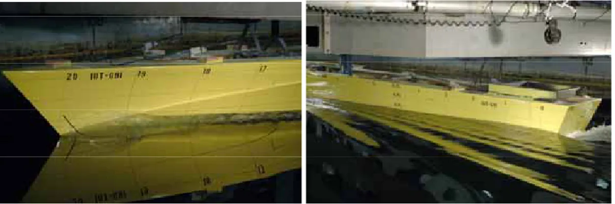
A photograph of the completed bare hull model is provided in Figure 5:
Figure 5: 1:13.54 Scale HALIFAX Class Frigate Model
Description of Instrumentation: Tow force was measured using a 250 lb S-type load cell while model sinkage, heel and trim were measured using the tow post mounted yo-yo potentiometer and gimbal Rotational Voltage Displacement Transducers (RVDT) respectively. Water temperature was periodically measured manually using a hand-held digital thermometer submerged at the nominal mean draft depth.
Three NIKON D100 digital single lens reflex cameras were mounted on the tow carriage to take photographs of the steady state dynamic swell-up at the bow and stern as well as the wake during the steady state portion of each run.
All acquired analog DC signals were low pass filtered at 10 Hz, amplified as required and digitized at 50 Hz using IOT’s standard data acquisition system and software.
Description of Test Program: With the model ballasted to the 5.34 m full scale level trim condition, the full baseline resistance curve of the unappended model was evaluated as per the IOT standard resistance procedure (Reference 8) from 3.5 knots to 31.5 knots full scale with several repeat runs included for data verification. The evaluation of eight flaps, two chord lengths (1% and 1.5% of LBP) and four angles ranging from 4 to 13 degrees trailing edge down relative to the horizontal, was planned for the HALIFAX Class hull form (see table below).
Flap Angle (deg.) Chord (% LBP) Chord (m) – Full Scale
Designated L1A4 4 1 1.245 Designated L1A7 7 1 1.245 Designated L1A10 10 1 1.245 Designated L1A13 13 1 1.245 Designated L1P5A4 4 1.5 1.8675 Designated L1P5A7 7 1.5 1.8675 Designated L1P5A10 10 1.5 1.8675 Designated L1P5A13 13 1.5 1.8675
NOTE: Flap angles trailing edge down – relative to horizontal. LBP = 124.5 m full scale.
A sketch of a typical simplified flap with hard edges is provided in Figure 6:
Figure 6: Sketch of Simplified Flap
To optimize the available tank time, six point resistance experiments were carried out for each flap option in 5 knot increments from 5 to 30 knots full scale and initially compared online to a six point data set acquired for the unappended (no flap fitted) hull. After acquisition of the data for all the flap configurations, the six point curve for the
unappended model was repeated for verification. The data set was then reviewed and a full resistance curve acquired with the three most promising candidates for comparison with the full baseline curve. This test strategy was designed to acquire the necessary data
to determine the optimum flap for the existing HALIFAX Class frigates in an efficient manner. Photographs of the model during testing are provided in Figure 7:
Figure 7: Photographs of Model During Testing
Preliminary Test Results: A preliminary review of the relative performance of each flap option in comparison to the baseline unappended resistance data was evaluated using the data acquired during the abbreviated test program (6 point resistance curves) by plotting the Total Resistance Coefficient (CTM) for the Model (appended)/ Total Resistance
Coefficient (CTM) for the Model (unappended) vs. Froude Number where CTM was
determined using the following relationship: 2 5 . 0 M M M TM TM V S R C ρ =
RTM = total resistance for the model (N)
ρM = water density for the model test facility (kg/m3)
SM = wetted surface area of the model (m2)
VM = model speed (m/s)
Based on the results of this evaluation, the following three most promising flaps were investigated further by carrying out full resistance curves:
• 1% LBP chord length, 4 degree flap (L1A4) • 1% LBP chord length, 7 degree flap (L1A7) • 1.5% LBP chord length, 4 degree flap (L1P5A4)
Detailed Data Analysis and Optimum Flap Selection: Typically, adding a flap to a hull increases the resistance at lower speeds, at some point there is a crossover whereby there is a benefit at higher speeds. A typical plot of resistance induced by adding a flap relative to an unappended hull is provided in Figure 8:
Tow Force Comparison Between Unappended Hull/Flap L1P5A4 -30 -25 -20 -15 -10 -5 0 5 0 5 10 15 20 25 30 35
Forward Speed (knots)
Tow Force Diff. (N)
Flap L1P5A4
Figure 8: Relative Tow Force With/Without Flap Fitted
Effective power (PE) was then computed using both the ITTC’57 (Reference 9) as well as
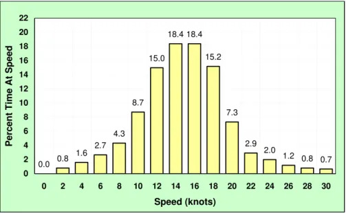
ITTC’78 (Reference 10) methodologies. A spline curve was fitted to the effective power data and interpolated from zero to 30 knots in two knot increments. The criteria for evaluating a given stern appendage was computed single ship annual consumption of fuel based on experimentally derived effective power using a Class-wide blended peace time percent time at speed profile (see Figure 9 below) for the HALIFAX Class hull form embedded in a DND Ship Endurance/Range Prediction EXCEL1 spreadsheet (Reference 11) that was tailored specifically for this project.
0.0 0.8 1.6 2.7 4.3 8.7 15.0 18.4 18.4 15.2 7.3 2.9 2.0 1.2 0.8 0.7 0 2 4 6 8 10 12 14 16 18 20 22 0 2 4 6 8 10 12 14 16 18 20 22 24 26 28 30 Speed (knots) Percen t T ime At Sp eed
Figure 9: HALIFAX Class Frigate Peace Time Percent Time at Speed Profile
1
EXCEL (© Microsoft Corporation) spreadsheets were used for all the Ship Endurance/Range Prediction analysis.
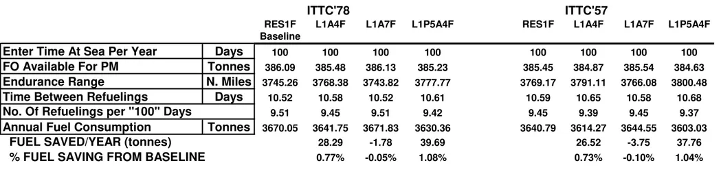
The single ship annual fuel consumption savings prediction based on the full resistance curve data was approximately 1% as provided in Table 1 at the end of this paper. Predicted amount of fuel saved per year and percent fuel saving from baseline (unappended ship) is also included in Table 1.
Conclusions & Recommendations: The trends observed in the IOT results acquired were generally similar to those reported in the open literature. Initially the addition of a flap increased resistance, with a crossover at roughly 15 knots full scale with significantly reduced fuel consumption provided for higher speeds. A minor reduction in both dynamic sinkage and trim angle due to the addition of a flap was also noted.
Bare hull resistance test data is assumed to be conservative since actual performance of full scale stern flaps have generally exceeded model scale predictions (Reference 2). Benefits provided by the stern flaps on the HALIFAX Class frigates are generally lower than reported in the literature for U.S. warships primarily due to the lower average speed of the peace time percent time at speed profile.
So in conclusion, eight flaps were investigated for the HALIFAX class hull form - two chord lengths (1% and 1.5% LBP) and four trailing edge down angles ranging from 4 to 13 degrees to the horizontal. Preliminary resistance results from the abbreviated (6 point) curves indicated only three of the flaps provided a benefit relative to the unappended hull. These three options were further investigated with full resistance curves. Applying the computed results to the fuel prediction algorithm supplied by DND, both 4 degree flaps (1% and 1.5% of LBP) provide a similar overall benefit with the longer chord length flap being slightly superior. A sketch of the final optimum flap with rounded edges to be fabricated for further validation tests is provided in Figure 10:
Figure 10: Final Flap Design for the Physical Model
5.0 ADDITIONAL FLAP VALIDATION EFFORT PLANNED The following effort is planned to further evaluate the final flap design:
1) Appended Resistance Experiments: Resistance experiments on the fully appended model over a forward speed range from 3.5 to 31.5 knots full scale with/without final flap in place ballasted to the 5.34 m level trim condition.
2) Self-Propulsion Experiments: Self-propulsion experiments at 6, 10, 14, 18, 22, 28 knots and full speed with the fully appended model fitted with/without the final flap design. IOT has recently procured the equipment necessary to propel this very large model at 30 knots full scale (4.193 m/s model scale) along with dynamometers to measure the propulsion parameters (shaft speed, torque and thrust). Stock 5-bladed warship propellers are available to propel the model. 3) Astern Manoeuvring: Astern manoeuvring will consist of steady speed astern
runs from 1 to 15 knots full scale as well as crash stops using speed profiles derived from actual full scale trials. All experiments will be carried out
with/without final flap design and dedicated instrumentation will be used assess the structural loads on the flap. Crash stop runs will include:
- 10 knots ahead full scale to full astern - 20 knots ahead full scale to full astern - high speed ahead to stop
- high speed ahead to full astern
4) Wake Survey: wake survey to be carried out specifically to acquire data for input to dedicated DRDC Atlantic software designed to evaluate any change in
propeller cavitation inception speed due to the presence of the final flap.
5) Full Scale Trials: Full scale trials are in the very early planning stage but could
include some or all of the following trials before and after any flap is fitted: calm water propulsion, manoeuvring including standard turning circles, zig zags, steady state astern test and crash stops, seakeeping, propeller viewing and hydrodynamic noise evaluation on a sound range. Presumably the final flap as fitted to the HALIFAX Class would look similar to the flap installed on the USS Curtus Wilbur (DDG 54) shown in Figure 11 from Reference 2.
An investigation is also planned with a 2 m transom extension option. For this configuration, a preliminary investigation has shown an improvement in resistance of greater than 4% over the existing hull.
Figure 11: Stern Flap Installed on the USS Curtus Wilbur (DDG 54)
6.0 SECONDARY BENEFITS OF STERN FLAPS
If a flap was fitted to the HALIFAX Class frigate hull form, the full scale influence should conform to those listed in the open literature (Reference 12) including:
• Delivered power reductions a few percent greater than the resistance reduction due to improved propulsive efficiency;
• Reduced propeller loading; • Reduced vibration and noise;
• Increased cavitation inception speed;
• A reduction in both near field and far field wave energy;
• A slight increase in maximum forward speed; and generally positive impacts in terms of emissions from ship internal combustion engines.
Thus over the next few years, assuming the required funding is secured, the Canadian Navy should start deriving the many benefits from installation of stern flaps to this critical naval asset.
7.0 ACKNOWLEDGEMENTS
Funding for this project was provided by DND. The authors would like to thank all IOT technical staff that assisted with this project.
8.0 REFERENCES
1) Sutherland, Capt. (N) R.A., Dumbrille, Cdr. L.P., Stenson, Cdr. M.A., “The Canadian Patrol Frigate: Today’s Technology”, Proc. of the ASNE Symposium: Destroyer, Cruiser and Frigate Technology, Biloxi & Pascagoula, Mississippi, October 2 – 4, 1986, pp. 197-249.
2) Cusanelli, D.S., Karafiath, G.,”Advances in Stern Flap Design and Application”, 6th International Conference on Fast Sea Transportation (FAST’01), September 4 – 6, 2001, Southampton, U.K.
3) Cusanelli, D.S., Percival, S.,”CFD Development and Model Test Evaluation on an Integrated Wedge-Flap for the DDG 79 Flight IIA”, NSWCCD-50-TR—2001/024, September 2001.
4) Thornhill, E., Hally, D, ”CFD Analysis of Stern Flap Configurations for the Canadian Patrol Frigate”, DRDC Atlantic TR 2005-219, Defence R&D Canada – Atlantic, 2005. LIMITED DISTRIBUTION
5) Hally, D, ”Potential Flow Calculations of the Effect of Stern Flaps and Wedges on the Canadian Patrol Frigate”, DRDC Atlantic TR 2005-220, Defence R&D Canada – Atlantic, 2005. LIMITED DISTRIBUTION
6) Thornhill, E., ”CFD Calculations of the Effect of Stern Flaps and Wedges on the Canadian Patrol Frigate”, DRDC Atlantic TR 2005-254, Defence R&D Canada – Atlantic, 2005. LIMITED DISTRIBUTION
7) “Construction of Models of Ships, Offshore Structures, and Propellers”, IOT Standard Test Method GM-1, V9.0, October 28, 2004.
8) “Resistance in Open Water”, IOT Standard Test Method TM-1, V6.0, April 2, 2004. 9) Proceedings of 8th International Towing Tank Conference (ITTC), Madrid, Spain,
1957.
10) ITTC Recommended Procedure 7.5-02-03-01.4, “1978 International Towing Tank Conference (ITTC) Performance Prediction Method”, 1999.
11) Dervin, M.F.,”Ship Endurance / Range Prediction”, DND Reference #D-03-002-010/SG-001, (EXCEL Workbook), 2005.
12) Cusanelli, D.S.,”Stern Flaps – A Chronicle of Success at Sea (1989-2002)”, Innovations in Marine Transportation, SNAME Northern California Section Joint Section Meeting, Pacific Grove, California, May 30 – June 2, 2002.
ITTC'78 ITTC'57
RES1F L1A4F L1A7F L1P5A4F RES1F L1A4F L1A7F L1P5A4F
Baseline
Enter Time At Sea Per Year Days 100 100 100 100 100 100 100 100
FO Available For PM Tonnes 386.09 385.48 386.13 385.23 385.45 384.87 385.54 384.63
Endurance Range N. Miles 3745.26 3768.38 3743.82 3777.77 3769.17 3791.11 3766.08 3800.48
Time Between Refuelings Days 10.52 10.58 10.52 10.61 10.59 10.65 10.58 10.68
9.51 9.45 9.51 9.42 9.45 9.39 9.45 9.37
Annual Fuel Consumption Tonnes 3670.05 3641.75 3671.83 3630.36 3640.79 3614.27 3644.55 3603.03
FUEL SAVED/YEAR (tonnes) 28.29 -1.78 39.69 26.52 -3.75 37.76
% FUEL SAVING FROM BASELINE 0.77% -0.05% 1.08% 0.73% -0.10% 1.04%
No. Of Refuelings per ''100'' Days
Table 1: Predicted Annual Fuel Consumption for Three Optimum Flaps Peace Time Percent Time at Speed Profile