Publisher’s version / Version de l'éditeur:
IAVSD 2011 : 22nd International Symposium on Dynamics of Vehicles on Roads
and Tracks : 14-19 August 2011, 2011-08-14
READ THESE TERMS AND CONDITIONS CAREFULLY BEFORE USING THIS WEBSITE.
https://nrc-publications.canada.ca/eng/copyright
Vous avez des questions? Nous pouvons vous aider. Pour communiquer directement avec un auteur, consultez la première page de la revue dans laquelle son article a été publié afin de trouver ses coordonnées. Si vous n’arrivez pas à les repérer, communiquez avec nous à [email protected].
Questions? Contact the NRC Publications Archive team at
[email protected]. If you wish to email the authors directly, please see the first page of the publication for their contact information.
NRC Publications Archive
Archives des publications du CNRC
This publication could be one of several versions: author’s original, accepted manuscript or the publisher’s version. / La version de cette publication peut être l’une des suivantes : la version prépublication de l’auteur, la version acceptée du manuscrit ou la version de l’éditeur.
Access and use of this website and the material on it are subject to the Terms and Conditions set forth at
Stochastic Modeling Applied to Vehicle-Track Performance and Safety
Huang, Wei; Magel, Eric; Liu, Yan
https://publications-cnrc.canada.ca/fra/droits
L’accès à ce site Web et l’utilisation de son contenu sont assujettis aux conditions présentées dans le site LISEZ CES CONDITIONS ATTENTIVEMENT AVANT D’UTILISER CE SITE WEB.
NRC Publications Record / Notice d'Archives des publications de CNRC:
https://nrc-publications.canada.ca/eng/view/object/?id=e1bd66ea-0641-4a8b-b033-7b2239bd713d https://publications-cnrc.canada.ca/fra/voir/objet/?id=e1bd66ea-0641-4a8b-b033-7b2239bd713dStochastic Modeling Applied to Vehicle-Track Performance and Safety
Wei Huang, Eric Magel and Yan LiuCentre for Surface Transportation Technology (CSTT) National Research Council Canada (NRC) 2320 Lester Road, Ottawa, Ontario K1V 1S2, Canada
e-mail address of lead author: [email protected]
Abstract
The application of a Monte-Carlo stochastic modeling technique to simulate a loaded coal car fleet running over a sharp curve has successfully reproduced the distributions of wheel/rail forces measured in the field. In the case of lateral force, wheel/rail friction and contact conditions are found to have the highest impact among the many parameters evaluated. For vertical force, the unevenly loaded condition is identified as one of the key factors. To better diagnose truck performance based on wheel/rail force measurements collected by the Truck Performance Detector (TPD), normalization methods to reduce “false alarms” due to non-truck factors such as wheel/rail friction and contact conditions are required.
1. INTRODUCTION
Wheel/rail lateral and vertical forces, as well as their ratios, have been widely used to describe the performance and safety of rail vehicle-track systems. In recent years, the wayside Truck Performance Detector (TPD) has been applied to monitor wheel/rail forces in North American railroads for freight cars equipped with three-piece trucks [1]. It has been found that the measured wheel/rail forces have a quite large scatter [2]. For example, the sections below show that the recorded lateral force on the high rail side of the leading axle in a fleet of loaded coal cars can differ by a factor of more than 10. It has been generally suggested that the freight cars/trucks associated with the high lateral forces are “bad performers” and should be sent to the shop for maintenance. However, wheel/rail forces are sensitive to many factors including wheel profile, wheel/rail friction, truck component health (e.g. conditions of adapter, wedge, constant contact side bearing and center plate), as well as rail profile, track geometry and track stiffness at the wayside location. There exist wide variations in the vehicle and track conditions, and many of these conditions (such as surface friction and truck conditions) are difficult to measure. There are many “false alarms” reported by the TPD, and some of these may be associated with the un-measured non-truck conditions. To address this issue and to improve the accuracy of TPD monitoring systems, it is important to understand the effects of the above mentioned multiple parameters on the wheel/rail forces. Because the problem involves multiple parameters, a dynamic simulation using the traditional method of parameter study is impossible to cover the whole parameter matrix space. For example, 18 parameters with 5 values each generate a 4 trillion case matrix. In this paper we discuss a stochastic dynamic model that was developed and applied to the wayside measurement issue. With properly defined statistical inputs for both vehicle and non-vehicle parameters, the model randomly selects values for the various parameters based on a Monte Carlo simulation technique and conducts thousands of virtual wayside simulations. By matching the wheel/rail force distributions with test ones, the randomness or stochastic distributions of multiple conditions are calibrated. The major vehicle and non-vehicle factors that affect the wheel/rail force distribution on curves are studied.
2. STOCHASTIC (MONTE CARLO) SIMULATION
Monte Carlo simulation has been used to solve many scientific and engineering problems, including in the rail engineering field [3][4][5]. As the first step to employing this technique in dynamic simulations of rail vehicle – track systems, considerable efforts have been taken to build and calibrate a stochastic model to see if it can reproduce the wheel/rail force distributions measured in the field. The modelling is based on vehicle/truck models developed previously in VAMPIRE™, a commercial package for railway vehicle dynamics simulation [6]. To facilitate an efficient Monte Carlo simulation with a large number of permutations, a special automation module has been developed based on AutoRD (Automatic Rail Dynamic simulation system [7]), a proprietary NRC-CSTT software package. The module includes a pre-processing unit that automatically builds a large number of Monte Carlo realizations from random values of various parameters characterized by either measured or estimated distributions. The fully transient and non-linear dynamic simulations are then conducted through a special batch process making use of multiple CPUs. The post-processing part of the tool is able to automatically generate the distributions of assigned variables used for the data analysis.
modeling and calibration. Most of the trucks used in the coal car fleet were frame braced. Measured lateral and vertical force values for the high rail side of the leading axle were used for comparison and calibration [2]. The force measurement was conducted in May to July period in 2004 without application of any lubrication or friction management. The test site for the wheel/rail force measurements was on a single, 6.5 degree, right-hand curve with 2-inch super-elevation, with a balance speed of 21 mph (34 kph). The measured super-elevation, curvature, alignment, profile and gauge of an 1165-ft long length of track were used in the computer model. The rail profiles on both high and low rails were measured and used in the simulations. Track geometries and rail profiles have been assumed to have only minor changes during the force measurement period and therefore take no random variation in the Monte Carlo simulations.
0 1 2 3 4 5 6 7 8 254 260 267 274 281 287 294 301 GRL (kip) % / k ip
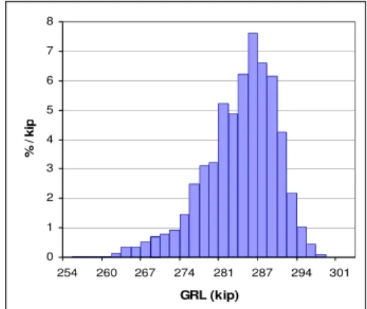
Figure 1 Loaded coal cars Figure 2 Gross Rail Load (GRL) distribution
0 5 10 15 20 25 30 35 40 45 50 15 18 22 25 28 Speed (mph) % / mp h
Figure 3 Measured distribution of vehicle speed
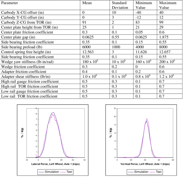
The measured data for gross rail load (GRL), operating speeds and wheel profiles of the loaded coal car fleet are available and were used in the Monte Carlo simulation. The car GRL values were randomly selected from measured values of the loaded coal car fleet. The histogram of the measured vehicle GRL is shown in Figure 2. The vertical axis values have been normalized by the bin width so that the area under the curve is 100%. The vehicle GRL value with the highest occurrence number is 286 kips. The histogram of the measured vehicle speed data is shown in Figure 3. The speed value with the highest occurrence number is 25.4 mph. There are 1166 measured wheel profiles of coal cars that the Monte Carlo module randomly selects from for each simulation. Other vehicle and track parameters are all based on truncated normal (Gaussian) distributions. The four parameters required to define these distributions are the mean value, the standard deviation, the minimum value and the maximum value. The stochastic input parameters using this distribution include carbody mass properties with consideration of uneven loading conditions, truck mass properties, center plate gap and friction, side bearing preload and friction, main spring free height, wedge friction, warping stiffness, axle adapter (pad) stiff-ness and wheel/rail friction coefficients. The values to define the distributions for some of the key parameters are summarized in Table 1. These values are first estimated by experience and best engineering judgement, and then adjusted through calibration iterations. For the carbody X and Y center of gravity (CG) offsets, X is an offset in the longitudinal direction and Y in the lateral. Z-CG is the height of the CG above the top of rail (TOR).
With the distribution for each input parameter defined, a large number of realizations (simulations) were built with randomly selected parameters or conditions. For this study 5000 simulations were conducted to calculate the distributions of the lateral and vertical wheel/rail forces under the randomly generated parameter sets. The stochastic distributions of multiple conditions are adjusted by trial and error to match the calculated wheel/rail force distributions with test ones. The distribution (histograms) of simulated lateral and vertical force on the high rail side of the leading axle are compared with those of the measured histograms in Figure 4. It can be seen that very good agreement has been achieved for both lateral and vertical forces.
Table 1 Eighteen stochastic input parameters are used in this analysis
Parameter Mean Standard
Deviation
Minimum Value
Maximum Value
Carbody X-CG offset (in) 0 10 -40 40
Carbody Y-CG offset (in) 0 3 -12 12
Carbody Z-CG from TOR (in) 91 2 83 99
Center plate height from TOR (in) 25 1 21 29
Center plate friction coefficient 0.3 0.1 0.05 0.6
Center plate gap (in) 0.0625 0.55 0.0625 1.875
Side bearing friction coefficient 0.35 0.1 0.15 0.55
Side bearing preload (lb) 6000 1000 4000 8000
Control spring free height (in) 12.563 3 11.626 12.657
Side bearing friction coefficient 0.35 0.1 0.15 0.55
Wedge yaw stiffness (lb-in/rad) 180 x 106 10 x 106 160 x 106 200 x 106
Wedge friction coefficient 0.3 0.2 0 0.6
Adapter friction coefficient 0.4 0.1 0.2 0.6
Adapter shear stiffness (lb/in) 1.0 x 10⁶ 0.1 x 10⁶ 0.8 x 10⁶ 1.2 x 10⁶
High rail gauge friction coefficient 0.5 0.3 0.1 0.7
High rail TOR friction coefficient 0.5 0.3 0.1 0.7
Low rail gauge friction coefficient 0.5 0.3 0.1 0.7
Low rail TOR friction coefficient 0.5 0.3 0.1 0.7
0 1 2 3 4 5 6 7 8 9 -10 0 10 20 30 40
Lateral Force, Left Wheel, Axle 1 (kips)
% / k ip Simulation Test
0 2 4 6 8 10 12 0 20 40 60 80
Vertical Force, Left Wheel, Axle 1 (kips)
% /
k
ip
Simulation Test (a) (b)
Figure 4 (a) Histogram of measured and simulated lateral force on the high-rail wheel of leading axle (b) Histogram of measured and simulated vertical force on the high-rail wheel of leading axle
3. ANALYSIS OF SIMULATION RESULTS
The wheel/rail force distributions with large scatter such as those shown in Figure 4 are due to wide variations in the vehicle and track conditions, and many of the conditions that cause this (like surface friction and truck wear) are difficult to measure in the field. In computer simulations these conditions can easily be identified by simply examining the input parameters. Eighteen parameters were studied in the present simulation [7]. But a traditional parameter matrix approach that includes 18 parameters with five values for each would result in a prohibitively large 4 trillion case matrix. Instead, a Monte Carlo approach was used to simulate thousands of cases by randomly selecting values for 18 statistically defined parameters that mimic the range of potential conditions existing in the real operating environment. After first reproducing the measured histogram of wheel/rail forces through computer simulation, it is then possible to conduct a parameter analysis for an extended set of vehicle
and track conditions. Effects of a number of conditions on wheel/rail forces have been studied including truck warping stiffness, unbalanced loads, various states of wheel wear (i.e., different wheel profiles), surface friction on the high and low rails, side bearing friction coefficient, side bearing preload and vehicle speed [7].
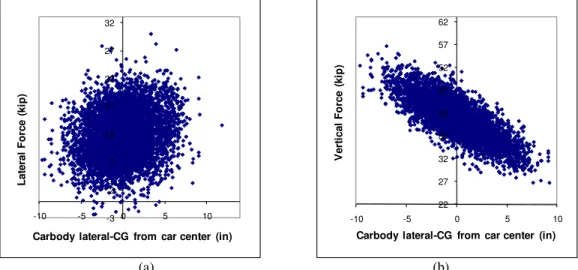
For example, Figure 5 shows the effects of lateral position of carbody CG on lateral and vertical force on the high rail side of the leading axle. Positive carbody CG lateral position is the offset towards the low rail. It can be seen clearly in Figure 5 (b) that shifting the carbody CG towards the low rail leads to lower vertical force on the high rail. Not surprisingly, the present results show that the lateral unbalanced loading condition has a significant effect on wheel/rail vertical force. The correlation between the lateral unbalanced loading and lateral force shown in Figure 5 (a) is much weaker than in the case of the vertical force.
-3 2 7 12 17 22 27 32 -10 -5 0 5 10 La te ra l Forc e ( k ip )
Carbody lateral-CG from car center (in)
22 27 32 37 42 47 52 57 62 -10 -5 0 5 10 V er ti c al F o rce (ki p )
Carbody lateral-CG from car center (in)
(a) (b)
Figure 5 (a) Effect of carbody CG lateral position on lateral force, high rail side, leading axle (b) Effect of carbody CG lateral position on vertical force, high rail side, leading axle
Figure 6 (a) shows the effects of high-rail gauge-face friction coefficient on lateral force on the high-rail side of the leading axle. It can be seen that lower values of gauge-face friction coefficient on the high-rail generally leads to higher lateral force. As gauge-face friction coefficient does not have any significant effect on vertical force, the consequence of lower gauge-face friction coefficient is higher L/V ratios. However, it does not necessarily lead to higher derailment risk as the Nadal limit is higher at lower friction coefficients. Figure 6 (b) shows the effects of low-rail TOR friction coefficient on lateral force on the high-rail side of the leading axle. Low-rail TOR friction coefficient generally has an opposite effect on lateral force in comparison with high-rail gauge-face friction coefficient. Therefore, the increase of lateral force due to gauge-face lubrication on a high rail may be mitigated with friction management on the low rail TOR.
-3 2 7 12 17 22 27 32 0.1 0.3 0.5 0.7 L a te ra l For c e ( k ip)
High rail gauge friction coefficient
-3 2 7 12 17 22 27 32 0.1 0.3 0.5 0.7 La te ra l Fo rc e ( k ip)
Low rail TOR friction coefficient
(a) (b)
Figure 6 (a) Effect of low-rail TOR friction coefficient on lateral force, high-rail side, leading axle (b) Effect of high-rail gauge-face friction coefficient on lateral force, high-rail side, leading axle
Another analysis approach was pursued in order to identify the key parameters which could shift lateral force from a case where the value is very low to a case where it is very high, or vice verse. Two simulation cases, one resulting in the highest lateral force in the distribution of Figure 4(a) (called “high lateral force case” hereafter) and another randomly picked from the low end of the distribution (called “low lateral force case #1”), were
analyzed to determine the key parameters responsible for a lateral force change from very low to very high.Then
extra simulation cases were conducted in which the parameters were changed step by step from the parameters in low lateral force case #1 to the parameters in high lateral force case. For example, Step 1 is to change wheel/rail contact profile from the profile in low lateral force case #1 to the profile in high lateral force case. All other parameters are the same as those in low lateral force case #1. In the same way, Steps 2 to 6 are performed and the lateral force obtained after each step are compared. In this stepwise migration from low lateral force case #1 to high lateral force case, the largest changes in lateral force occurred when the wheel/rail contact profile and wheel/rail friction coefficients were changed. Two other lateral force cases were picked randomly and the same analysis with the stepwise migration was conducted. Similar results were obtained showing that the wheel/rail contact profile and wheel/rail friction coefficients produce the highest impact on lateral force. The sequence of parameter changes did not have any significant impact on the results.
To further elucidate the effects of wheel/rail contact profile and wheel/rail friction conditions, detailed analysis was conducted for two groups of simulations from the 5000 realizations. These groups are (A) the lowest 1% lateral force and (B) the highest 1% lateral force in the distribution shown in Figure 4 (a). Each group contains about 50 runs. As seen in Figure 4 (a), the lateral force of the leading axle on the high rail for the loaded coal car could be as high as 30,000 lb at the high end, and as low as a few thousand pounds at the low end. The average value of the lateral force for the group (A) is 1,480 lb and the average for group (B) is 25,700 lb. After scanning the input conditions for those 100 or so simulations, the features of the friction configurations and wheel / rail profiles are identified. Figure 7 compares the friction coefficients of the two groups, both on the gauge-face of the high rail and on top of the low rail. It can be seen that the high lateral force of group (B) is related to high friction on top of the low rail and low friction on the gauge-face of the high rail. In the case of group (A) for the lowest 1% lateral force cases, the friction on the top of the low rail is significantly lower than the friction on the high rail gauge-face.
0.70 0.68 0.67 0.69 0.14 0.10 0.10 0.36 mean 0.48 mean 0.31 mean 0.29 mean 0.61 0.00 0.10 0.20 0.30 0.40 0.50 0.60 0.70 0.80
High Rail Gauge Low Rail TOR High Rail Gauge Low Rail TOR
Wh eel / Rai l CO F
Group A ‐ lowest 1% Lateral Force Group B ‐ highest 1% Lateral Force
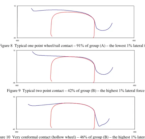
Figure 7 Comparison of wheel/rail friction between the lowest 1% and the highest 1% lateral forces A scan of the wheel/rail contact inputs in the simulations of group (A) found that 91% of the cases have one-point-contact with a mildly worn wheel. Figure 8 shows a typical wheel/rail contact on a high rail in this group. The root portion of the wheel profile can be considered as the “best” shape, since it produces the one-point-contact that is one of the main contributing factors to the low lateral force. As for group (B), 88% of the simulation cases have one of two types of wheel / rail contact features. The first is typical two-point-contact with slightly worn wheels, while the second is one-point-contact with heavily worn (hollow) wheels. Examples of these two wheel / rail contact types are shown in Figure 9 and Figure 10, respectively. These results confirm that the wheel/rail contact condition (and hence wear) is one of the controlling factors for lateral force.
-40 10
-850 -650
Figure 8 Typical one point wheel/rail contact – 91% of group (A) – the lowest 1% lateral force
-40 10
-850 -650
Figure 9 Typical two point contact – 42% of group (B) – the highest 1% lateral force
-40 10
-850 -650
Figure 10 Very conformal contact (hollow wheel) – 46% of group (B) – the highest 1% lateral force
4. CONCLUSIONS
This work demonstrates that Monte-Carlo stochastic modeling techniques can be used to evaluate the perfor-mance and safety of rail vehicles with a range of load, design, wear and environmental conditions. The strategy and method used for the Monte-Carlo simulation of a loaded coal car fleet running over a sharp curve success-fully replicates the distributions of wheel/rail forces measured in the field. This success suggests a promising dir-ection for using dynamics simulations to evaluate operating performance and safety based on distributions of interested indices on a system level. For example, the effect of friction management can be estimated by the dis-tribution of the lateral force or wear number that takes into account various conditions of the whole vehicle fleet. For vertical force, the uneven loading condition is identified as one of the key controlling factors. In the case of lateral force, wheel/rail friction and contact conditions are found to have the strongest impact among other input parameters. For condition monitoring based on Truck Performance Detector (TPD) measurements of wheel/rail forces, the development of normalization methods to reduce “false alarms” due to non-truck factors such as wheel/rail friction and contact conditions is necessary.
Acknowledgments
The sponsorship of the Federal Railroad Administration of the U.S. Department of Transportation is gratefully acknowledged.
References
[1] A. Coe, Sarunac, R and Wiley, R B: Wayside Truck Performance Detector Based Rail Car Preventive Maintenance, Investing Today for a Brighter Tomorrow, Proceedings of the 2006 Rail Conference, American Public Transportation Association, 2006.
[2] P. Sroba and K. Oldknow, 100% Effective Friction Management, NRC-CSTT report, August 2005. [3] J. Liu: Monte Carlo Strategies in Scientific Computing, Springer, 360 pages, 2008.
[4] M. Keramat and R. Kielbasa: Modified Latin hypercube sampling Monte Carlo (MLHSMC) estimation for average quality index, Analog Integrated Circuits and Signal Processing, 19, 87–98, 1999.
[5] J. Oscarsson: Dynamic Train-Track Interaction: Variability Attributable to Scatter in the Track Properties, Vehicle System Dynamics, 37, 59-79, 2002.
[6] Delta Rail: User manual of Vampire, 2010. [7] Y. Liu: User Instruction of AutoRD, 2009.
[8] W. Huang and Y. Liu: Stochastic Modeling Applied to Vehicle-Track Performance and Safety, Technical report CSTT-RVC-TR-173, NRC-CSTT, 2010.

![[PDF] Base de données relationnelle Access concepts de base - Cours Access](data:image/gif;base64,R0lGODlhAQABAIAAAP///wAAACH5BAEAAAAALAAAAAABAAEAAAICRAEAOw==)