HAL Id: tel-01905831
https://tel.archives-ouvertes.fr/tel-01905831
Submitted on 26 Oct 2018
HAL is a multi-disciplinary open access archive for the deposit and dissemination of sci-entific research documents, whether they are pub-lished or not. The documents may come from teaching and research institutions in France or abroad, or from public or private research centers.
L’archive ouverte pluridisciplinaire HAL, est destinée au dépôt et à la diffusion de documents scientifiques de niveau recherche, publiés ou non, émanant des établissements d’enseignement et de recherche français ou étrangers, des laboratoires publics ou privés.
systems : a language to model behaviors of reactive
agents
Paulo Pimenta
To cite this version:
Paulo Pimenta. Application of model-driven engineering to multi-agent systems : a language to model behaviors of reactive agents. Multiagent Systems [cs.MA]. Université Montpellier, 2017. English. �NNT : 2017MONTS031�. �tel-01905831�
Délivré par l'Université de Montpellier
Préparée au sein de l'école doctorale I2S
Et de l'unité de recherche UR GREEN - Cirad
Spécialité: Informatique
Présentée par Paulo Pimenta
Application of Model-driven
engineering to multi-agent
systems: a language to model
behaviors of reactive agents
Soutenue le 5 Janvier 2017 devant le jury composé de:
M. Jacques Ferber Professseur Université de Montpellier Pres. du Jury
M. Jean-Pierre Müller HDR CIRAD Dir. de thèse
M. David Hill Professseur Université Blaise-Pascal Rapporteur
M. Jean-Michel Bruel Professseur Université de Toulouse Rapporteur
M. Mamadou Kaba Traore Mâitre de conference/HDR Université Blaise Pascal Examinateur M. Fabien Michel Mâitre de conference/HDR Université de Montpellier Examinateur M. Jaime Simao Sichman Mâitre de conference Universidade de São Paulo Invité
iii
“Façamos da interrupção um caminho novo. Da queda um passo de dança, do medo uma escada, do sonho uma ponte, da procura um encontro”
v
Abstract
Many users of multi-agent systems (MAS) are very commonly disinclined to model and simulate using current MAS platforms. More specifically, modeling the dynamics of a system (in particular the agents’ behaviors) is very often a challenge to MAS users. This issue is more often observed in the domain of socio-ecological systems (SES), because SES domain experts are rarely pro-grammers. Indeed, the majority of MAS platforms were not conceived taking into consideration domain-experts who are non-programmers. Most current MAS tools are not dedicated to SES, or nor do they possess an easily understan-dable formalism to represent the behaviors of agents. Moreover, because it is platform-dependent, a model realized in a given MAS platform cannot be pro-perly used on another platform due to incompatibility between MAS platforms. To overcome these limitations, we propose a domain-specific language (DSL) to describe the behaviors of reactive agents, regardless of the MAS platform used for simulation. To achieve this result, we used model-driven engineering (MDE), an approach that provides tools to develop DSLs from a meta-model (abstract syntax), textual editors with syntax highlighting (for the concrete syn-tax) and code generation capabilities (for source-code generation of a model). As a result, we implemented a language and a textual editor that allow SES domain experts to describe behaviors in three different ways that are close to their natural expression: as equations when they are familiar with these, as a sequence of activities close to natural language or as an activity diagram to re-present decisions and a sequence of behaviors using a graphic formalism. To demonstrate interoperability, we also developed code generators targeting two different MAS platforms (Cormas and Netlogo). We tested the code generators by implementing two SES models with the developed DSL. The generated code was targeted to both MAS platforms (Cormas and Netlogo), and successfully simulated in one of them. We conclude that the MDE approach provides ade-quate tools to develop DSL and code generators to facilitate MAS modeling and simulation by non-programmers. Concerning the DSL developed, although the behavioral aspect of MAS simulation is part of the complexity of modeling in MAS, there are still other essential aspects of model and simulation of MAS that are yet to be explored, such as model initialization and points of view on the model simulated world
vii
Acknowledgements
Tout d’abord, je voudrais remercier le Conseil National de Développement Scien-tifique et Technologique (CNPq) au Brésil pour le financement de cette thèse et l’opportunité de progresser dans ma carrière scientifique. Je remercie aussi le co-directeur de cette thèse, Pierre Bommel, pour m’avoir invité au sein de l’unité de recherche GREEN, au CIRAD, pour commencer la longue journée qui est une thèse. Puis je voudrais remercier le directeur de cette thèse, Jean-Pierre Müller, pour m’avoir fait confiance malgré les connaissances plutôt légères que j’avais en septembre 2012 sur le système multi-agents. Je lui remercie pour sa patience, ses encouragements, ses indications et pour m’avoir délégué une responsabilité dans un projet ambitieux, où j’ai trouvé mon propre chemin.
Mes remerciements vont également à toute l’unité de recherche GREEN pour l’accueil pendant les quatre ans de thèse. Plus spécialement, à Martine Antona et à Aurélie Botta pour le soutien pendant toute la période de ma thèse, mais également à Jean-François Tourrand et Marie-Gabriele Pikety pour les moments de discussion (et surtout d’amitié) qui m’ont énormément aidé dans les mo-ments critiques de ce travail.
Je remercie Amaury, Paulo, Claudio Almeida, Moises et leurs familles pour l’accueil en France, pour les conseils et pour les moments très conviviaux en famille. Je ne sais comment exprimer ma gratitude à vous tous. De la même façon, merci aux amis Francesca, Antonio, Sylvain et Victor pour leurs encoura-gements et pour les très bons et agréables moments au CIRAD.
Je remercie les Profs. David Hill et Jean-Michel Bruel qui ont accepté d’être les rapporteurs de cette thèse, et de participer au Jury. Ils ont également contri-bué par leurs nombreuses remarques et suggestions à améliorer la qualité de ce mémoire, et je leur en suis très reconnaissant.
Enfin, ces remerciements ne seraient pas complets sans mentionner mes amis chercheurs qui ont joué un rôle très spécial pour le début de cette thèse : René Poccard et Marcelo Thales. C’est grâce à eux que j’ai pu commencer cette thèse. Merci à vous.
ix
Contents
List of Figures xv
List of Tables xvii
List of Codes xvii
List of Abbreviations xxi
1 General introduction 1
1.1 Context . . . 1
1.2 Objectives . . . 2
1.3 Outline . . . 3
2 Modeling and simulation behavior of multi-agent systems 5 2.1 Introduction . . . 5
2.2 Behavior and MAS . . . 6
2.2.1 Cognitive behavior . . . 7
2.2.2 Goal-based behavior . . . 8
2.2.3 Reactive behavior . . . 10
2.3 Participatory Modeling and MAS . . . 11
2.3.1 Background . . . 11
2.4 Experiences of MAS tools used in participatory modeling . . . 12
2.4.1 CORMAS . . . 12
2.4.2 NetLogo . . . 13
2.4.3 Anylogic . . . 14
2.4.4 GAMA . . . 15
2.4.5 MIMOSA . . . 17
2.5 Limits of the current MAS tools used in participatory modeling . 19 2.5.1 The Challenge of MAS behavior simulation in SES . . . 19
2.5.1.1 Programming language learning . . . 19
2.5.1.2 MAS behavior representation . . . 20
2.5.2.1 Domain specific language for MAS behavior
mo-deling . . . 21
2.5.2.2 Platform independence . . . 22
2.5.2.3 Visual tools to model with stakeholders . . . 23
2.6 Conclusion . . . 24
3 Model driven engineering 25 3.1 Introduction . . . 25 3.2 Background . . . 26 3.3 Model . . . 28 3.4 Modeling Language. . . 30 3.5 Meta-model . . . 31 3.6 Model Transformation . . . 32
3.7 Model driven engineering . . . 33
3.8 The Eclipse Modeling Project . . . 34
3.8.1 Overview . . . 34
3.8.2 EMF . . . 35
3.8.3 Abstract syntax development . . . 37
3.8.4 Concrete syntax development . . . 38
3.8.4.1 TMF . . . 40
3.8.4.2 GMF . . . 42
3.8.5 Model-to-text transformation . . . 44
3.8.6 Model-to-model transformation . . . 45
3.9 Conclusion . . . 47
4 Modeling social-ecological systems 49 4.1 Introduction . . . 49
4.2 The ECEC Model . . . 50
4.2.1 The plant and its behavior . . . 51
4.2.2 The Foragers and its behavior . . . 51
4.2.3 The foragers’ energy consumption behavior . . . 52
4.2.4 The foragers’ feeding behavior . . . 52
4.2.5 The foragers’ reproductive behavior . . . 52
4.2.6 The foragers’ move behavior . . . 52
4.2.7 The foragers’ die behavior . . . 53
4.2.8 Model initial values and execution . . . 53
4.3 ECEC behavior representation. . . 54
xi
5 B-Reactive - A DSL to model reactive behaviors in MAS 57
5.1 Introduction . . . 57
5.2 The Semantic domain . . . 57
5.3 Abstract syntax for reactive behavior . . . 64
5.3.1 The model . . . 64
5.3.2 The EntityClass . . . 65
5.3.3 Behaviors . . . 65
5.3.3.1 Activity Diagram Behaviors . . . 66
5.3.3.2 Activity Behaviors . . . 67
5.3.3.3 Primitive Activities . . . 68
5.3.3.4 Equation Behaviors . . . 70
5.3.4 Expressions . . . 70
5.3.4.1 Variable Class . . . 71
5.3.4.2 Function Call Expressions . . . 71
5.3.5 Initialization . . . 72
5.4 Concrete syntax . . . 73
5.4.1 A model declaration . . . 73
5.4.2 The Entities declaration . . . 74
5.4.3 Attributes, Parameters and Local variables declaration . . 74
5.4.4 The Behavior declaration . . . 75
5.4.4.1 Equation Behavior . . . 76
5.4.4.2 Activity Behavior . . . 76
5.4.4.3 Activity Diagram Behaviors . . . 77
5.4.5 Function Expressions. . . 81 5.4.5.1 Location Functions . . . 82 5.4.5.2 LocationSet Functions . . . 83 5.4.5.3 Entity Functions . . . 84 5.4.5.4 EntitySet Functions . . . 85 5.4.5.5 Boolean Functions . . . 86 5.4.5.6 Numeric Functions . . . 87 5.4.6 Model initialization. . . 87 5.4.7 Conclusion . . . 89
6 Implementation of B-Reactive language using MDE 91 6.1 Introduction . . . 91
6.2 Application of MDE . . . 91
6.3 Implementing a textual editor with XText . . . 92
6.3.0.2 Add new validation rules . . . 95
6.4 Abstract syntax analysis of the target language . . . 98
6.5 Building code generators . . . 100
6.5.1 Code generation of Netlogo procedures . . . 101
6.5.1.1 Generating Breedings, Turtles and Patches . . . . 102
6.5.1.2 Generating Setup procedures . . . 102
6.5.1.3 Generating command and reporter procedures . 103 6.5.1.4 Generating the go procedure . . . 104
6.5.2 Code generation of Cormas methods . . . 104
6.5.2.1 Generating Cormas classes . . . 106
6.5.2.2 Generating methods for the accessing protocol . 107 6.5.2.3 Generating methods for the instance-creation pro-tocol . . . 107
6.5.2.4 Generating methods for init protocol . . . 108
6.5.2.5 Generating methods for control protocol . . . 108
6.5.2.6 Generating methods for probes protocol . . . 109
6.5.2.7 Generating methods for custom protocols . . . . 109
6.6 Model simulation . . . 110 6.6.1 Netlogo simulation . . . 110 6.6.2 Cormas simulation . . . 111 6.7 Conclusion . . . 111 7 General conclusion 113 7.1 Discussion . . . 113
7.1.1 MDE as an approach for designing DSL for SES . . . 113
7.1.2 Cyclic approach for developing a DSL . . . 115
7.1.3 Evaluation of DSL and simulation of generated code . . . 115
7.2 Future works. . . 116
7.3 Conclusion . . . 118
A SES axmodels in B-Reactive language 119 A.1 Implementation of ECEC model in B-Reactive language . . . 119
A.2 Implementation of prison rebellion model B-Reactive language . 122 B Generated code 125 B.1 Cormas generated code for ECEC model. . . 125
B.2 Cormas generated code for Prison rebellion model . . . 126
B.3 Netlogo generated code for ECEC model . . . 127
xiii
C M2T Acceleo templates 133
C.1 Netlogo M2T templates. . . 133
xv
List of Figures
2.1 A human behavior process : from cognitive to reactive behaviors 6
2.2 A cognition process.Source : Sowa,2011 . . . 8
2.3 An example of goal based behavior "satisfy hunger" and the many activities that might be executed by the intelligent agent to achieve his goal . . . 9
2.4 A finite state machine representing a reactive behavior . . . 10
2.5 Cormas activity diagram tool to interpret agent’s behavior. Source : Bommel and Dieguez,2011. . . 13
2.6 Netlogo in a participatory modeling experience for human epi-demiological study. Source : Maharaj et al.,2011 . . . 14
2.7 Agents’ behavior parametrization on Anylogic. Source : Tàbara et al.,2007 . . . 15
2.8 GAMA and the interaction view in the urban emergency mana-gement context Source : Chu et al.,2012 . . . 16
2.9 Mirana and Household behavior. Source: Aubert and Müller,2013 18 3.1 MDA’s official logo . Source : OMG,2014 . . . 27
3.2 Model-Driven Engineering (Adapted from : Cabot,2009) . . . 28
3.3 MDA models . . . 29
3.4 Main elements of a modeling language. . . 30
3.5 The 4-layered architecture of Meta-Object Facility. Source : Euro-pean PhD School on Robotic Systems,2016 . . . 32
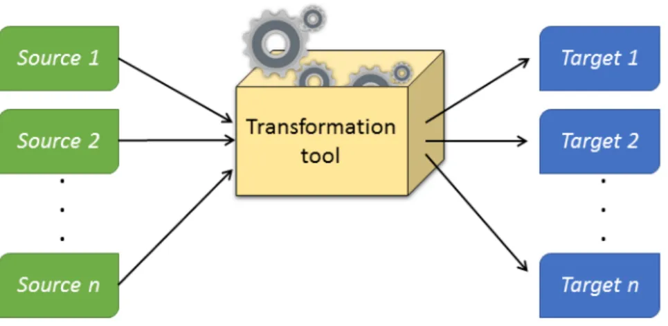
3.6 Model Transformation. . . 33
3.7 Eclipse Modelig Project and its projects . . . 35
3.8 A simplified version of the Ecore meta-model. Source : Eclipse Foundation,2016(a) . . . 36
3.9 The meta-modeling process. Source : Eclipse Foundation,2016(a) 37 3.10 The parsing process . . . 39
3.11 Abstract and concrete syntax . . . 39
3.12 Abstract and concrete syntax. Adapted from : Jan Köhnlein,2009 41 3.13 The GMF process for generating graphical concrete syntax. Adap-ted from Eclipse Foundation,2016(b) . . . 42
3.14 Template approach mechanism in M2T. Source : Brambilla et al., 2012 . . . 44
3.15 Model to model transformation (M2M) . . . 45
4.1 ECEC representation : Foragers distributed in a spatial grid of plants . . . 51
4.2 Activity diagram representing the sequence of behaviors to be
executed during an ECEC model simulation . . . 53
4.3 Diffrent ways to represent a behavior in ECEC . . . 55
5.1 A model definition and its elements . . . 58
5.2 A different way to explain behaviors . . . 59
5.3 Terms used by domain experts to model SES . . . 60
5.4 An example of behavior described in natural language and its main elements . . . 61
5.5 The Model . . . 64
5.6 EntityClass . . . 65
5.7 Behavior . . . 66
5.8 Activity diagram behavior (a) and its subtype of nodes : Control-Node(b) and ExecutableNode(c) . . . 67
5.9 ActivityBehavior . . . 68
5.10 Primitive Activity class diagram . . . 69
5.11 ActivityDiagramBehavior . . . 70
5.12 Expression class diagram. . . 70
5.13 VariableClass class diagram . . . 71
5.14 FunctionCallExpression . . . 72
5.15 Init . . . 72
5.16 Syntax diagram for a model definition . . . 74
5.17 Syntax diagram for an entity definition . . . 74
5.18 Syntax diagram for attributes, parameters and local variable de-finition . . . 75
5.19 Syntax diagram for an equation behavior and its equation . . . . 76
5.20 Syntax diagram for the activity behavior . . . 77
5.21 Syntax diagram for the activity diagram behavior . . . 77
5.22 Syntax diagram for control nodes . . . 78
5.23 Syantax diagram for primitive activities . . . 80
5.24 Syntax diagram for the max-one-of location function. . . 83
5.25 Syntax diagram of SelectConditionedLocation function . . . 84
5.26 Syntax diagram of function OneOfEntity . . . 85
5.27 Syntax diagram of Entities function. . . 85
5.28 Syantax diagram for InitEntity and InitSpace rules . . . 88
6.1 Cyclical process of MDE application to obtain a DSl textual editor with code generator capabilities . . . 92
6.2 A dsl textual editor generated by Xtext . . . 96
6.3 A textual editor containing a message of OCL constraint violation 97 6.4 B-reactive editor after implementation of validation rules . . . 98
6.5 General abstract syntax for Cormas and Netlogo models . . . 99
6.6 B-reactive editor after implementation of validation rules . . . . 101
6.7 B-reactive editor after implementation of validation rules . . . . 106
xvii
List of Tables
3.1 Model-to-model technologies available in EMF . . . 46
4.1 ECEC model’s initial values . . . 54
5.1 B-Reactive’s semantic domain . . . 61
xix
List of Codes
5.1 Model declaration . . . 74
5.2 Entity declaration . . . 74
5.3 Attributes and Parameters declaration . . . 75
5.4 Equation behavior definiton . . . 76
5.5 Activity Behavior definiton . . . 77
5.6 Activity diagram behavior definition . . . 81
5.7 Location expression examples . . . 83
5.8 LocationSet expression examples . . . 84
5.9 Entity function example . . . 85
5.10 Entity set function example . . . 86
5.11 Boolean functions example. . . 86
5.12 Entity set function example . . . 87
5.13 Model initialization . . . 88
B.1 Generated instance-creation method of ECEC model. . . 125
B.2 Generated code for die behavior of ECEC model . . . 126
B.3 Netlogo generated code for ECEC model . . . 127
B.4 Netlogo generated code for ECEC model . . . 129
C.1 Acceleo file generator template . . . 133
C.2 Acceleo file generator template for Netlogo code generation . . . 133
C.3 Breed, patch and turtles declaration . . . 134
C.4 Code generation for turtles setup . . . 134
C.5 Code generation for environment setup . . . 135
C.6 Behavior . . . 136
C.7 Transformation of Equation Behaviors into Netlogo procedures . 136 C.8 Transformation of Acvitity Behaviors into Netlogo procedures . . 137
C.9 Netlogo code generation into primitive activities . . . 137
C.10 Mapping Acvitity Diagram Behaviors into Netlogo procedures . 138 C.11 The go procedure . . . 139
C.12 Cormas classes generation . . . 140
C.13 Code generation for accessing protocol methods in Cormas . . . . 141
C.15 Methods code generation for the init protocol . . . 143
C.16 Method code generation for the control protocol . . . 143
C.17 Methods code generation for the probes protocol . . . 144
xxi
List of Abbreviations
MAS Multi-Agent Systems
PM Participatory Modeling
M&S Model and Simulation
SES Social-Ecological Systems
MDA Model Driven Architecture
MDD Model Driven Development
MDE Model Driven Engineering
EMF Eclipse Modeling Framework
EMP Eclipse Modeling Project
OMG Object Management Group
FIPA Foundation for Intelligent Physical Agents
MOF Meta Object Facility
M2M Model-to-Model
M2T Model-to-Text
MOFM2T MOF Model-to-Text
DSL Domain Specific Language
xxiii
To my family, for their dedicated partnership and love
in every moment of my life.
1
Chapter 1
General introduction
1.1
Context
As in any interdisciplinary context, terms that eventually have the same mea-ning can be differently described by domain experts. Social-ecological systems (SES) are no exception. The domain of SES is an interdisciplinary domain that focuses on understanding and investigating how society relations influence the environment and vice-versa. In this context, Modeling and Simulation (M&S), is one way to understand these inherently complex relations. In (M&S), one must make use of available computer platforms that are able to capture and represent such complexities.
In the past decade, modeling and simulation (M&S) has been used as a pro-mising approach that can give understandings to natural phenomena (Jarrah et al., 2015). Modeling and simulation (M&S) has the ability to increase our understanding of systems, to evaluate them or to predict their evolution (Tou-raille et al.,2012). At the same time, some Participatory Modeling (PM) appro-aches have been developed (Andersen et al., 2007; Etienne, 2014; Cardwell et al., 2009), aiming to build a common methodology to design model with sta-keholders. One of the key objectives of PM is the attempt to actively involve all stakeholders (e.g. designers, developers, experts, end-users, etc.) in the de-sign process to help ensure that the dede-signed product meets their needs and is indeed usable (Chu et al.,2012).
One of the available approaches in the (M&S) field is the multi-agent systems approach (MAS). MAS allows the modeler to assume the role of an agent du-ring a simulation and thus, to characterize its rules from the ego perspective. Reactivity, autonomy, pro-activity and ability to react to other agents are among the main characteristics that define an agent (see (Ferber,1999) for a broader de-finition), where reactivity is specified by set of action-state rules (Bandini et al.,
2009). Reactive agents simply retrieve a pre-set of behaviors similar to reflexes, without maintaining any internal state. Thus, actions contained in that type of behavior can be easily programmed.
Since MAS platforms have been increasingly used to deal with ecological and socioeconomic issues (Promburom, 2002), combining them with PM approa-ches might be a very efficient method for modeling and discussing social en-vironmental systems. However, even if most of the existing MAS tools share the common basic concepts about what an agent is (role, interaction, reactivity, etc.), current modeling languages differ in the approach of how those concepts are modeled. Consequently, modeling in most of these tools requires stakehol-ders to adapt to a specific platform philosophy or programing language.
Although the reactivity of an agent can be relatively easy to program, using con-cepts (i.e. programing language concon-cepts) that are not related to what partici-pants desire to model is one of the reasons why involving them inthe modeling process is not an easy task. Another reason is that most stakeholders are not programmers and thus, may be reluctant to spend much time on the project. Sometimes they are forced into a predefined top-down procedure, or the tools and models at their disposal are fitted with pre-fabricated black boxes that they cannot understand and assess (Ramsey,2009).Consequently, the absence of in-tuitive tools using identical vocabulary to that used by stakeholders, may have contributed to their lack of interest in M&S.
1.2
Objectives
Our objective in this thesis is to investigate how new technologies and compu-ter modeling approaches can tackle the problems previously mentioned. More specifically, our focus will be the abstraction of some MAS models in SES dom-ain and platform coding details.
Our first goal is to create a structure of syntactic terms based on the observation of common terms that reflect stakeholder’s vocabulary to describe behaviors. To this end, we should consider how behaviors are specified before they are modeled. This specification should contain terms and relations that are more familiar to stakeholders. After identifying such terms, we should be able to construct an abstract syntax and use it to develop a programing language (con-crete syntax) that will be as close as possible to the vocabulary used to specify behavior in SES models.
1.3. Outline 3 Our second goal is to develop a high-level abstraction language that allows practitioners to focus on modeling without worrying about the simulation as-pect. This language should offer enough expressibility to make use of domain terms stakeholders are more used to. As in any language, formalisms should be respected and for that reason, validation syntax rules should be implemented to ensure model validity. Additionally, since the simulation aspect should not be of concern to stakeholders, neither should the specificities of MAS platforms (such as initialization, agents activation and programming language). To solve this issue, we should provide code generators for any specific MAS platform.
1.3
Outline
This thesis is structured into five main chapters. Chapter 2 provides an over-view of Modeling and simulation behavior of multi-agent systems. The first sections focus on how behaviors can be specified in MAS, starting with a brief section of what is our vision of a computer agent. The next sections are dedica-ted to MAS tools used in PM for modeling behavior, followed by an analysis of some of these tools limitations, and possible improvements that could be done in these tools.
Chapter 3 focus on Model-Driven Engineering (MDE) software development methodology. We begin with some background theory and explanation of some terms and definitions commonly used by the MDE and some initiatives that implement MDE. Then, we dedicate the rest of the chapter to the description of the MDE modeling framework we actually used for our works, namely the Eclipse Modeling Project. We show how Eclipse Modeling Framework tools could be used to develop domain-specific languages.
In Chapter4, we introduce an example of MAS model in the domain of biology. To explain this model, we focus on how agents and their behaviors are usually described by non-programmers. Chapter 5is dedicated to the definition of an abstract syntax based on stakeholders’ specification that was captured by a par-ticipatory methodology. We describe a meta-model that was conceived based on terms existing in the SES model introduced in Chapter 4. This meta-model is used as an abstract syntax and, in further sections, we explain the semantic domain and propose a concrete syntax from the conceived meta-model.
Chapter6demonstrates the application of Eclipse Modeling Framework to de-velop a textual editor for a domain-specific language in order to model and
initialize reactive behaviors on MAS. The framework is also used to implement code generators for two specific MAS platforms. The code generators are tested by using 2 SES models implemented with the language proposed in Chapter
5. Later, the generated code is analyzed and used in MAS simulations. Finally, we conclude this thesis in Chapter7, where we discuss the main contributions exposed in this document, along with some avenues for future works.
5
Chapter 2
Modeling and simulation behavior
of multi-agent systems
2.1
Introduction
In the domain of artificial intelligence, an intelligent agent can be defined as a computational autonomous entity with perception, reactivity and pro-activity abilities (Wooldridge et al.,1995). However, several authors differ in their point of views on these concepts (Franklin and Graesser,1997) and we still are lacking a consensual definition (Dent,2007)
A broadly accepted definition for intelligent agents, however, is that of an en-capsulated computer system that is situated in a certain environment and ca-pable of autonomous actions and interactions capabilities (Wooldridge, 2009). An autonomous action can be seen as the ability of an agent to decide for them-selves in order to satisfy their design objectives. Interaction capabilities can be understood as the ability to mimic our social everyday behaviors, such as cooperation, coordination and negotiation. In this sense, Multi-Agent Systems (MAS) arises from the idea of systems adopting an agent-oriented view of the world, which involves multiple agents and the relationships between them In this chapter, we discuss how their autonomous behaviors can be expressed, while we explain the most common types of behaviors present in the majority of MAS. Our goal is also to provide an overview of some PM experiences using MAS platforms and how those platforms were used to express agent behaviors. Finally, we will present some challenges linked to modeling with stakeholders using current MAS tools, some limitations of the previously presented tools, and possible improvements to be applied to those tools.
2.2
Behavior and MAS
Intelligent agents can be classified from many different perspectives, accor-ding to their intelligence degree (Russell et al., 1995): reflex agents, goal-based agents, utility-based agents and learning agents; or according to their functiona-lities (Hostler et al.,2005): collaborative agents, reactive agents, mobile agents, interface agents, etc. But those classifications do not focus on the behavioral aspect of an agent. In (Nilsson, 1998), this particular aspect is defined as the process of mapping perceptions to actions. Yet, according to the author, this process can be broken down into the following sequential steps: Sensor data, Perception, Cognition, Reasoning, Goal-setting, Evaluation, Action validation, Action Performance and Learning. Without exhaustively discussing each one of these steps, we provide an example that illustrates the relation between these steps, represented in Figure2.1.
Figure 2.1 – A human behavior process : from cognitive to reactive behaviors In figure 2.1, a prehistoric human hunting process is used as an example of behavior process. The whole hunting process as a behavior, is divided in many steps. Even if the main behavior is to attack an animal, the attack itself is neither the first nor the last behavior in the whole hunting process. Some steps, such as sensing and perception, are fundamental for goal definition. In the example illustrated in Figure 2.1, depending of the noise or hunting environment, the hunter may decide to wait, or follow the prey a little while more. Defining a goal or a strategy is also part of the hunting process. They serve as parameters for the final action to be taken by the hunter: attacking the prey. Note that
2.2. Behavior and MAS 7 attacking the prey may also involve a set of actions: attacking on the left, on the right, run and attack, attack and run, wait, move left, surround the prey and attack, etc. These sets of actions can be considered as reactive behaviors.
The learning process (although out of the scope of this work) is also worth to mention, since is the last (and a fundamental) part of any intelligence behavior. Learning behavior is the capacity of acquiring experience for further decision making. Or as defined by (Michell, 1997), "a computer program is said to learn from experience E with respect to some task T and some performance measure P, if its performance on T, as measured by P, improves with experience E". As a subfield of ar-tificial intelligence, machine learning makes use of several available techniques (genetic algorithms, neural networks and many others) that are applied to MAS learning capacity.
Since the focus of this work is the behavioral aspect of MAS, we classify the agent’s behavior into 3 types of behaviors: cognitive behavior, goal-based beha-vior and reflexive behabeha-vior. These groups were defined based on more detailed definitions of agents behavior made by (Russell et al.,1995), and a classification proposed by (Demazeau and Müller,1990).
2.2.1
Cognitive behavior
Cognition is the mental action or process of acquiring knowledge and under-standing through experience, and the senses1. Cognition is largely studied in
the fields of linguistics, neuro-science, psychiatry, biology, computer science and many others. Cognition processes are studied by cognitive science, an inter-disciplinary scientific field that seeks to understand how cognitive mental processes work. More precisely, it tries to understand how conscious mental behavior, such as the behavior of thinking, understanding, learning, and re-membering, are processed in the human brain. Nevertheless, this process can be more or less complex according to the type of intelligence we want to mi-mic. In the simplistic scheme in Figure2.2, the number of steps required to take an action is directly proportional to the complexity of the individual taking this action. In this case, humans may be able to process a higher number of steps be-fore displaying any type of behavior, by contrast with simple organisms found in nature.
Figure 2.2 – A cognition process.Source : Sowa,2011
One of the main characteristics of an intelligent agent is their capacity of au-tonomous actions in the environment, in order to meet their objectives (Wool-dridge et al., 1995). But the ability to perceive that environment is also part of a cognitive behavior of any intelligent agent. In that sense, as an interdis-ciplinary study of philosophy, psychology, artificial intelligence, etc, cognition science played a major role in defining cognition architectures for the percep-tion of intelligent agents. One example is the ACT-R theory (short of "Adaptive
Control of Thought Rational") proposed by the psychologist John Anderson. In the work titled "The Architecture of Cognition" (J. Anderson,1996), Anderson uses ACT-R theory (J. R. Anderson,1983) to develop a formal architecture that provides capabilities to simulate cognition.
Many other cognitive architectures were also derived from ACT-R theory, such as SOAR (Newell, 1992), CLARION (Ron, 2006), EPIC (Kieras et al., 1997), ADAPT (Benjamin et al., 2001), and others. The aim of such architectures is to provide a common computer programming architecture that allows, based on ACT-R theory concepts, to specify knowledge-intensive reasoning, reactive execution, hierarchical reasoning, planning, and learning from experience.
2.2.2
Goal-based behavior
A goal-based behavior comes from the idea of a goal: to construct a plan to change current (or given) world state into a desired world state. Those states area analogous to states contained finite state machines (FSM). In finite state machines, states change from one to another when a required (or a set of) con-dition(s) is detected. In A.I, FSM can be used by agents as a representation of how their states change when a certain event is perceived on the agent’s envi-ronment or when it is triggered by another agent.
2.2. Behavior and MAS 9 A simple example of FSM would be an automatic door: a door has a state "open" and "closed" that changes between one to another whenever the door sensor detects the presence ("open") or absence ("close") of someone close enough to it. But instead of focusing on how states change, defining a goal-based behavior is instead to define what is the goal of an agent. In other words, based on a set of available and simple tasks, a goal-based behavior does not focus on how those simple tasks are implemented. Rather, a goal-based behavior specifies situations that are desirable.
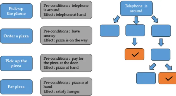
Consider, for instance, a simplified behavior tree example given in Figure2.3. In this example, a hypothetical agent has one single goal: to satisfy their hunger. Given a set of actions (on the left of Figure2.3), and some pre-conditions to each activity (on the middle of Figure 2.3), a behavior tree is specified in order to achieve a goal. In the example, action "pick up the telephone" has, as an effect, the "telephone at hand" state. The telephone, however, can be at close range (in this case, the agent would just have to pick it up) or the telephone can be far (he would have to move), or not in the agent’s range (triggering another action to search for the telephone). In any way, the goal "telephone at hand" would be achieved, but in more or less time. Depending on the weight attributed to some specific actions, the slowest option might also be the best one.
Figure 2.3 – An example of goal based behavior "satisfy hunger" and the many activities that might be executed by the intelligent agent to achieve his goal
On one hand, if a more refined behavior is specified, goal-based behavior may have multiple goals and this could lead to a non-deterministic behavior. But
incorporating goal-based behaviors to MAS can greatly enhance the intelligence of agents.
2.2.3
Reactive behavior
Also termed Simple Reflex Behavior by (Nilsson, 1998), the basic notion of reactive behaviors was first defined in the field of behaviorist psychology by John Broadus Watson, in 1925. By using the notion of "S-R" (Stimulus-Reaction) scheme (see Figure2.2), any a priori "reasoning" is excluded between S and R, where S is considered as a particular perception of the environment containing the entity, and R as a sequence of basic actions.
One key difference between reactive behaviors and the previously discussed type of behaviors is that in the first, actions are based on the agents current perception or the environment, and not on past perceptions. For example, con-sider a robot that would be required to gather a specific type of soil sample (peaty soil) from a specific place. Considering that the action of gathering a soil sample is a simple reactive behavior, if the robot finds the same soil sample in a different place, it would then still gather new samples. The robot does not take into account that it has already collected samples. That idea is illustrated through an FSM in Figure2.4.
Figure 2.4 – A finite state machine representing a reactive behavior
The reactivity showed in the example above is quite straightforward. It is very similar to a human reactive behavior (e.g. when we dodge something approa-ching us at a very high speed).
2.3. Participatory Modeling and MAS 11
2.3
Participatory Modeling and MAS
2.3.1
Background
In participatory modeling, Role Playing Games (RPG) are very often used as an interactive and collaborative storytelling approach to simulate models. Some approaches successively used RPG on PM for discussion with stakeholders (see D’Aquino et al.,2002for a list of 5 PM experiments using RPG). Combining RPG with M&S allowed modelers to use RPG as an observation and data collection tool to develop MAS simulation models. It allows individuals to play an active part in their participation, by concretely set out the issues (Gourmelon et al., 2013). But even if that type of approach is very effective for model discussion, in the end the model is almost entirely developed by researchers.
This could lead one to believe that RPG are enough to simulate models, and MAS would not be of much use. Yet, as stated by (Barreteau et al., 2000) two points must be considered. One is that RPG alone as a modeling tool are repor-ted to be limirepor-ted as they are cumbersome and slow to develop, and analysis of their results is still difficult. Another point is that comparison between different experiments using RPG is difficult since many parameters in a game are not controlled.
To overcome these issues, computer games based on repeated RPG observations were developed. That is the case of FishBanks (Meadows et al.,2015),a multi-player web-based simulation in which participants play the role of fishermen and seek to maximize their income as they compete against other players and deal with variations in fish stocks and in their catches.
One of RPG concepts is that, by taking the part of a character in the game, the player must follow rules that have been previously defined by the game creator. This affords, however, little flexibility to players during a game, since rules can-not be changed. In real case scenarios, such as natural resources management for example, discussions can last hours due to natural conflict of interest bet-ween stakeholders. Also, the addition of new rules or new parameters might be necessary. Rules flexibility of should be considered if we wish to capture how stakeholders mediate and solve their conflicts. This understanding is essential to capture the ways they behave.
The fact is that, in most cases, scientists are inclined to favor the tools that they are most familiar and comfortable with (Voinov and Francois Bousquet, 2010).
As a result, some works (as described in section 2.4) tried to incorporate new tools into MAS platforms. Their aim was to add new visual or textual langua-ges to facilitate the M&S process and consequently, behavior modeling with stakeholders. Some of these experiences are presented in the next section.
2.4
Experiences of MAS tools used in participatory
modeling
2.4.1
CORMAS
From COmmon-pool Resources and Multi-Agent Simulations, Cormas (François Bousquet et al.,1998) is a MAS tool that focuses on models for renewable natural resource management. According to the authors, CORMAS is oriented towards the representation of interactions between stakeholders about the use of rene-wable natural resources. Based on the VisualWorks programming environment, users can develop their model using SmallTalk programming language.
Used in several PM works2, CORMAS provides some facilities to interpret (and
modify) the behavior of agents during M&S. An executable activity diagram (Figure 2.5) allows to directly change the behavior of agents through a UML activity diagram. The diagram is, in turn, interpreted by the agents and can be modified by the users to redefine the order on which behaviors will be executed. The diagram was used in ((Bommel, Dieguez, et al., 2014, and Bommel and Dieguez, 2011)).The authors stated that, although the aim of the tool was not to generate the entire simulator code, it was able to improve the collective mo-dification of a model. Moreover, the tool was based on a simplified version of UML’s activity diagram. Since a tool based on a full specification of UML’s activity diagram could discourage potential users, a simpler version enabled anyone involved in the modeling process to participate more actively.
2An exaustive list models (but not all involving PM) can be found at : http://cormas.cirad.fr/en/applica/tousmodeles.htm
2.4. Experiences of MAS tools used in participatory modeling 13
Figure 2.5 – Cormas activity diagram tool to interpret agent’s behavior. Source : Bom-mel and Dieguez,2011
2.4.2
NetLogo
NetLogo (Wilensky, 1999) is a multi-agent programmable modeling environ-ment. Netlogo allows quick development and prototyping from simple to com-plex models. That is due to the fact Netlogo programming language is based on the Logo language, a dialect of Lisp that was designed for learning and ot-her educational purposes. As a result, Netlogo’s data structures (such as words and lists) closely parallel the words, phrases, and sentences that make up spo-ken and written language. Plus, logo-based languages provide the user with a good feedback on individual instructions, helping in the debugging and lear-ning process.
With many applications in a plethora of domains3, agents in Netlogo are
pro-grammed in the form of turtles, patches, links and the observer. The most cited MAS tool in the last decade (Page et al., 2012), NetLogo uses grids, bars and charts to represent agent’s environment and interactions. It also offers a Sy-stem Dynamics Modeler, which allows the user to draw diagrams that define populations of agents as "stocks" and flows.
In a PM experience concerning contagious human diseases (Maharaj et al.,2011), the authors developed a graphical user interface (GUI) for Netlogo to be used in participatory experiments aiming at investigating human attitudes toward the risk of being infected by a disease.
3Netlogo model library, also available in the version for download: http://ccl.northwestern.edu/netlogo/models/
Figure 2.6 – Netlogo in a participatory modeling experience for human epidemiological study. Source : Maharaj et al.,2011
2.4.3
Anylogic
AnyLogic (Borshchev, 2007) is a multi-paradigm modeling platform based on Java that provides capabilities to develop and combine agent-based models, system dynamics models, discrete-event models, and continuous and dynamic system models. Although AnyLogic does not focus on SES and though it is not under GNU GPL license, the platform has been used in some participatory modeling on SES domain.
In (Gaube et al., 2006) for example, AnyLogic was used for modeling the im-pacts of subsidy policy on farmer households, land use and nutrient flows. In this work, the behavior of the agents could be affected by the system they are part of and by changes in their environment (in this case, land use). Conse-quently, the behavior of the whole system would depend on the individual be-havior of each agent. The model was programmed in Java and later used in participatory processes.
Another example of Anylogic’s usage in the context of SES can be found in (Tàbara et al.,2007), where the authors aimed at using participatory modeling for integrated water sustainability assessment. Interestingly, the authors imple-mented a first version on Netlogo to describe the physical system ( that is, the hydrology system ) and the agent system that describes the behavior of different agents. Then, AnyLogic was applied to develop an agent model that represen-ted farmers (for agricultural water), electricians (for water dependency), frogs (water environmental use) and households (human water consumption besides agriculture). The agents could interact with and be influenced by their surroun-dings and the environment (the physical system) whereas the behavior of and
2.4. Experiences of MAS tools used in participatory modeling 15 decisions made by the agents were in turn reflected in the physical model. Fi-nally, certain initial parameters for the agents’ behaviors were defined by the players and assigned to the agents, as represented in (2.7)
Figure 2.7 – Agents’ behavior parametrization on Anylogic. Source : Tàbara et al.,2007
2.4.4
GAMA
The GAMA platform (Taillandier et al., 2012) - short for GIS & Agent-based
Modeling Architecture, is a modeling and simulation development environ-ment for building spatially explicit agent-based models. GAMA has its own modeling language (GAML - GAma Modeling Language) and it was based on XML. The GAML language focus is simplicity and considered by the authors to be as simple and easy to understand as the Netlogo modeling language (Taillan-dier, 2014). Gama has a declarative user interface, focusing on GIS and multi-layer 2D/3D visualization.
Although GAMA possesses many visualization options and a programming language focused on simplicity (GAML), few works relate that platform to PM experience. However, in (Chu et al.,2012) GAMA was applied in an approach proposal based on a participatory design to find the most effective way to mo-del human behavior. As a part of a broader PM methodology, a participatory design attempts to actively involve all stakeholders (e.g. designers, developers,
experts, end-users, etc.) in the design process to help ensure that the designed product meets their needs and is usable.
Figure 2.8 – GAMA and the interaction view in the urban emergency management con-text Source : Chu et al.,2012
In this work, the authors developed a model in the context of urban emer-gency management, aiming at the organization of resources and responsibilities for dealing with many aspects of emergencies occurring in cities (e.g. search and rescue of injured persons, extinguishing fires, etc).Among many available "views" (parameter view, chart view , display view, agent view, etc), GAMA provides the interaction view (Figure2.8), which shows the coordination occur-ring between the agents and allows the users to add or modify the messages they are exchanging. The messages, however, are modeled with GaML.
2.4. Experiences of MAS tools used in participatory modeling 17
2.4.5
MIMOSA
MIMOSA4 is a MAS platform aiming at providing tools capable of managing a
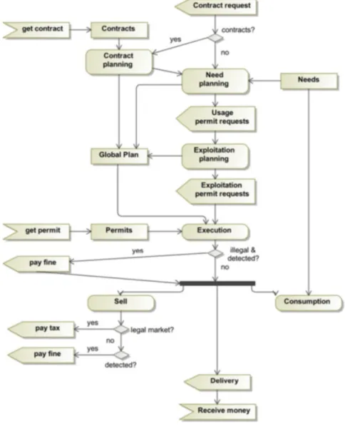
process from building conceptual models to running the simulations. Through a visual ontology editor, MIMOSA allows the description of the concepts, the structure and the relationship of agents to be made through ontologies. The modeled ontology can be used together with an extensible set of formalisms for model initialization and model visualization. Additionally, the conceptual model can be designed using a simplified UML class diagram. For the model dynamics (like agent’s behaviors), Mimosa allows the user to choose the forma-lism to be used, conditioning the possible states, and initialize model dynamics. Mimosa’s simulation kernel is based on DEVS (Zeigler and Sarjoughian,2003) In (Aubert, Müller, and Ralihalizara,2010), MIMOSA platform was used to de-velop an agent-based model called MIRANA. Mirana model aimed to evalu-ate the impacts of the management plans made by Malagasy local communities and explore the impacts of their decisions in scenarios. In this work, the concep-tual model was made of a set of ontologies describing the actors of the system (households, communities, etc.), objects on which they were acting on (lands, animal and plant species, etc.), actions carried out by the actors on the objects (hunting, cropping, etc.) and the regulations on the actions. The actors are pro-vided with needs (food, money, etc.) or objectives (conservation, production, etc.) and planning mechanisms. MIRANA model was composed of two kinds of dynamics: the first one was the biophysical dynamics, representing the po-pulation growth of the species and the evolution of the fertility expressed and represented as equations of time; the second one was the decision process of the agents, representing the households and the collective actors such as the local community.
In a more recent work (Aubert and Müller,2013), the authors improved the MI-RANA model by incorporating normative rules to models. An ontology was modeled considering definitions (and relations between) institutions, stakehol-ders, resources and territories. In the modeled ontology, the institutions and stakeholders respectively represented the "macro" and "micro" levels of des-cription. They considered institutions as a set of constitutive and regulative norms, where organization is a representation of a concrete group of people on whom the institution applies (e.g. household). Stakeholders were considered to 4From the french acronym for “Méthodes Informatiques de MOdélisation et Simulation
be exclusively active, human, individual or collective, decision-making parties with objectives. To represent the dynamics between MIRANA model elements, the authors used a mixture of natural language descriptions and UML activity diagrams. An example of dynamics representation is illustrated by Figure 2.9
where household behavior is conceptualized in an UML activity diagram
Figure 2.9 – Mirana and Household behavior. Source: Aubert and Müller,2013
In MIMOSA, the modeler has to define two types of models: the conceptual mo-del (that corresponds to the concepts and their relationships) and the concrete model (that corresponds the instantiation of the conceptual model). Those des-criptions are further used to generate a simulation model in the form of DEVS, and the whole model, written in Java.
2.5. Limits of the current MAS tools used in participatory modeling 19
2.5
Limits of the current MAS tools used in
partici-patory modeling
2.5.1
The Challenge of MAS behavior simulation in SES
In M&S, a formalism must be chosen if one desires to simulate a computer mo-del. Concerning SES, the chosen formalism should be able to provide most of the concepts involved in SES elements, such as territory, environment and ac-tors. These concepts are essential for MAS modeler behavior, especially if we consider that the way behaviors are modeled is strongly influenced by the way these concepts are formalized.
In MAS, the concept of environment is essential for M&S of agent-based models. Unfortunately, the multiplicity of disciplines involved in social environmental systems (SES) results in a non-consensus about many of the concepts involved in SES. To exemplify this, in his work titled "The Significance of Territory" (El-den, 2013), the author discusses how the concept of territory may vary from group to group. Not only do the concepts vary, but interests are also very diffe-rent. For instance, politicians see the territory as population aiming at resources while militaries view the territory as topographic features aiming at tactical and strategic actions. To jurists, the territory is a jurisdiction and delimitation since it aims at national and international laws. To the geographer, it could be a portion of space enclosed by boundary lines, but one interested in political geography might see the territory as a material, spatial notion establishing essential links between politics, people, and the natural setting.
Because of this diversity in disciplines involved in PM, it is still not very com-mon for stakeholders to find the concepts that they are used to in the current MAS platforms. Covering concepts from all disciplines does not seem to be a logical solution, even though a consensus on these concepts would be ideal. Providing stakeholders with a way of expressing their own concepts in a for-malism they could easily understand is a task still to be accomplished in MAS.
2.5.1.1 Programming language learning
One of the main obstacles for stakeholders during M&S phase is learning a new programming language. They tend to be discouraged during this stage because
a majority of stakeholders are not programmers. Additionally, much of stake-holders time during PM is consumed during sessions of discussing and con-ceptualizing a model. Furthermore, even non-programmer researchers might spend quite some time learning and applying a programming language to spe-cify behaviors in a given MAS platform.
In a PM experience concerning contagious human diseases for example (Maha-raj et al.,2011), the authors concluded that, although the tool was created to be interesting and engaging for participants, it is still very far from a real-world ex-perience of an epidemic reality. One of the reasons might be due to the fact that behaviors specified in the model were predefined by developers. Also, some MAS platforms (such as AnyLogic), "...have their use still confidential and regarded as “too advanced” or “too complicated” by many adaptation planning projects in PM (Drogoul,2015). Although there are more user-friendly platforms, and although enhancing the education and training of stakeholders and deciders could help overcome this issue, stakeholders still spend quite some time on training and learning programming languages, if they wish to simulate their model.
2.5.1.2 MAS behavior representation
Concerning the behavior aspect of MAS tools in most PM experiences, the be-havior represented is usually a reactive one. One possible reason is that the implementation of cognition and goal-based behavior could be very difficult to program, especially for non-programmers. Although the idea of following cognition and goal-based architectures would highly increase the detail level of a model description, following these architectures would proportionally incre-ase the complexity of representing that model. Certainly, this does not mean, though, that cognition and goal concepts are not present in MAS tools, but rat-her, that cognition and goal-based architectures should be implicitly incorpora-ted by developers of MAS platforms that are commonly used by stakeholders. In general, there are three ways to graphically represent behaviors in MAS si-mulation: through system dynamics, through DEVS, or through activity dia-grams. The last can be considered as a good ratio of intuitiveness/level of for-malization since it is also suitable for representing reactive behaviors due to its control flow nature. MIMOSA and CORMAS advocate the need for conceptual modeling before simulating models, providing an Ontology and an Activity di-agram editor, respectively, as a way to facilitate modeling.
2.5. Limits of the current MAS tools used in participatory modeling 21 Nonetheless, class diagrams and ontologies are only capable of describing the general structure of the model and relations between them. Which means that agents’ behaviors are always hand-coded by researchers. In the recent attempt (session 2.4.1) to increase stakeholders involvement during M&S process, the activity diagram editor only allowed users to visually modify the ranking of behaviors that were previously programmed by an expert modeler. The authors also stated that the tool does not prevent the modeler from programming his ABM.
Finally, the chosen formalism to represent a behavior should not be exclusi-vely coupled with the programming language paradigm of the chosen MAS platform. For example, if Netlogo and Anylogic provide many ways to model behaviors (like slide bars, text, stack and flow, etc), CORMAS on the other hand uses UML diagrams because, among other reasons, UML was designed to visu-ally represent models according to the object-oriented paradigm, and because CORMAS programming language (SmallTalk) is also object-oriented.
2.5.2
Possible improvements to current MAS tools
2.5.2.1 Domain specific language for MAS behavior modeling
Most MAS platforms presented so far are based on programming languages that were not designed through taking into account concepts present in a sta-keholders’ discourse. Correspondingly, stakeholders are forced to deal with programming language aspects and MAS platform specificities. To solve that issue, "what" a model should simulate must be separated from "how" the same model should be implemented. In other words, the simulation model must be separated from the conceptual model. This could be achieved by imple-menting an intermediary layer, significantly reducing M&S complexity for non-programmers. This intermediary layer could be represented by another pro-gramming language, composed of concepts that are common to modelers and stakeholders.
Many aspects (such as type system, implementation, etc.) are used to distin-guish and classify programming languages. Programing languages may also be distinguished by their type: they can be general-purpose languages (GPL), or domain-specific languages (DSL). GPLs are programming languages designed to be used for writing software in a wide variety of application domains. Java, Smalltalk, C++, are some examples of GPL. DSL on the other hand, can abstract
the design and implementation expertise of a domain: the DSL programmer fo-cuses on what to compute or to describe, as opposed to how instructions should be computed. Even if DSLs are less understandable for those who do not be-long to the targeted language domain, they are much more expressive in their domain, and consequently, a DSL exhibits minimal redundancy. Some exam-ples of DSL include HTML for web markup, SQL for relational database and Mathematica for symbolic mathematical computation.
Because domain-specific languages are more compact (Mernik et al.,2005; Fow-ler, 2010) and typically far less powerful than generic programming langua-ges, they communicate their intent far better. This is because DSLs do not in-clude many features found in general-purpose programming languages. While it is intended to increase expressiveness (thus decreasing maintenance cost), GPL contains features that also require a certain amount of domain and pro-gramming expertise when they are used. But stakeholders are mostly non-programmers, so the use of GPL may discourage them if they wish to simu-late their model. DSLs, on the other hand, could highly increase stakeholders’ participation level by incorporating some of their domain’s concepts in current MAS programming languages and tools (see Mernik et al., 2005 for an analy-sis of when and why DSLs should be developed and Kosar et al., 2010 for an empirical comparison between DSLs and GPLs).
With the exception of Netlogo and GAML, most programming languages used in the MAS platforms presented are GPL. However, neither Netlogo, nor GAML were specifically made for SES. But even if they can be used, and since social environmental systems are very often modeled using MAS platforms, we still lack DSLs for the SES domain.
2.5.2.2 Platform independence
As intuitive or user-friendly a MAS tool could be, it should be flexible enough to provide the user with tools for quick model validation. One way to validate a model is also to confirm the reproducibility of that model on any platform. But this way of model validation is still not possible in current MAS platforms because models are platform dependent. This means that specific platform ele-ments (such as icons, colors used and the how models are initialized on a speci-fic platform) are modeled along with the model specispeci-fication. The model should thus be platform-independent.
2.5. Limits of the current MAS tools used in participatory modeling 23 As an intermediary layer that separates the simulation model from the concep-tual model, DSLs may easily provide code generation facilities. One of DSL advantages are the ability to generate simulation models from conceptual mo-dels. This is achieved by defining text templates that read a model of the DSL and generate text files. Developers use domain-specific languages to construct models that are specific to their applications and use models to generate source code. Although building DSLs is not a recent approach, and has already been applied to MAS domain (Challenger et al.,2014,Demirkol et al.,2013), DSL code generation capabilities have never been used in PM, specially to describe the be-haviors of reactive agents.
2.5.2.3 Visual tools to model with stakeholders
CORMAS and MIMOSA use activity diagrams to model reactive agents beha-viors. But MIMOSA experience in PM only used activity diagrams during the conceptual stage of modeling. CORMAS provided stakeholders with a visual tool to "interpret" graphically model behaviors through an activity diagram, meaning that behaviors were previously defined. Additionally, behaviors were hand-coded by expert modelers and not by stakeholders.
Domain-specific languages are usually textual, but can also be visual. In that sense, visual languages are used to communicate a representation of a system, in order to understand or change it (Renger et al., 2008). "Thinking by dia-grams” (Blackwell, 2001) affords more efficiency than a text, or a stack of in-struction blocks. Also, they seem more powerful than textual description or lines of code, especially for collective design involving non-computer specia-lists such as local stakeholders (Bommel, Dieguez, et al.,2014). But computer simulations require some kind of formalism to run simulations. So, should a visual formalism be incorporated to a DSL capable of reproducing reactive be-haviors in MAS, then that visual formalism should also prove useful in promo-ting a multidisciplinary discourse among stakeholders (like activity diagrams, for instance).
In PM experiences, flux diagrams (such as activity diagrams) and cause-effect diagrams (such as ARDI5 (Etienne et al., 2011) are very popular among
stake-holders. These types of diagrams can provide a way to represent decisions (re-presented by agents behaviors on MAS). Moreover, the popularity of these dia-grams is due the fact that many policy makers start their professional education
by learning how to construct cause-effect diagrams and means-end branching trees (Mayer,2009). However, cause-effect diagrams poorly describe the spatial and environment aspects of an agent and these types of diagrams might not be enough to represent behaviors.
Nonetheless, a programmer’s mindset is still needed when using such visual modeling editors because "users have to deal with concepts such as if-then-else statements, loops, variables usage and so on" (Michel et al., 2011). Despite of that, visual modeling languages have great advantages. They have special virtues such as visualization, immediacy, spatiality, creativity, and compliance with intuition (Morand,2000).
2.6
Conclusion
In this chapter, we presented how behaviors are represented in some MAS ar-chitectures. Participatory modeling usually makes use of MAS tools because MAS is an individual-centered approach. In most PM experiences with MAS tools, reactive behaviors are the most used type of behavior due to their simpli-city of programming. Although many advances were made in the past decade, the current MAS platforms are still not able to sufficiently involve participati-ons in M&S simulation process. This is mainly observed in social environmental systems, where most stakeholders are non-programmers. Visual languages to represent reactive behavior, platform dependence and programming languages that are not specifically designed for SES domain are among the reasons why current MAS platforms are still far from keeping stakeholders’ level of partici-pation. It is undeniable that much work has been carried out in this field for the past decade, but much remains to be done. Still, we conclude that domain-specific languages should be designed for SES, to which some kind of visual formalism should be incorporated.
25
Chapter 3
Model driven engineering
3.1
Introduction
So far, we have been using the term "stakeholders" to denote a group of users (including researchers) for whom MAS platforms should be developed. Terms such as "clients" or "users" could also be applied.
Considering that stakeholders (including researchers) are experts in their own domain, the term "domain expert" seems more convenient to use. A domain expert is a person with special knowledge or skills in a particular area of en-deavor. The term domain expert is frequently used in expert systems software development, and there the term always refers to the domain other than the software domain. Therefore, the term "domain-expert" will be used instead. In the domain of software development, a programming language is usually used to develop a software. As previously introduced in chapter 2 progra-ming languages can be a general-purpose language (GPL) or domain-specific languages (DSL). DSL "are small, usually declarative, offering expressive po-wer focused on a particular problem domain" (Van Deursen et al.,2000). Also, MDE has adopted the term ’toolsmith’ to refer to developers that use graphical frame-works to build plug-ins. Although many methods for developing DSL are available in the literature, this chapter will focus on Model-Driven Engi-neering (MDE). We provide a brief overview of MDE, focusing on some of the necessary concepts to develop DSLs. Finally, we explore MDE’s perspective on those concepts and how they are implemented.
3.2
Background
Before getting into the "E" of MDE, some "MD" past initiatives should not be neglected if we are aiming at understanding MDE goals. Even before previ-ous model-driven initiatives (as illustrated in figure3.2), ), "various past efforts have created technologies that further elevated the level of abstraction used to develop software" (Schmidt,2006).
With little impact during the 1980s and 1990s, Computer-aided software engi-neering (CASE) focused on developing software methods and tools that ena-bled developers to express their designs in terms of general-purpose graphi-cal programming representations, such as state machines, structure diagrams, and data-flow diagrams. However, CASE tools were unable "to scale to handle complex, production-scale systems in a broad range of application domains" (Schmidt,2006). Later, developers start to typically use more expressive object-oriented languages, such as C++, Java, or C#. Re-usability was one of the main advantages that allowed such languages to implement complex solutions in ma-ture enough platforms. By using reusable functionality, middlewares (such as J2EE, .NET and the Common Object Request Broker Architecture - CORBA) were created in order to offer solutions to frequently encountered problems on development : heterogeneity, interoperability, security, dependability, etc. Later, developers started to typically use more expressive object-oriented lan-guages, such as C++, Java, or C#. Re-usability was one of the main advantages that allowed such languages to implement complex solutions in mature enough platforms. By using reusable functionality, middlewares (such as J2EE, .NET and the Common Object Request Broker Architecture - CORBA) were created in order to offer solutions to frequently encountered problems in development: heterogeneity, interoperability, security, dependability, etc.
Meanwhile, with the advances and the increasing popularity of other standards defined by the Object Management Group (OMG), the not-for-profit techno-logy standards consortium decided (around 2001), to adopt a new framework termed the Model Driven Architecture MDA. MDA is in fact, a set of many OMG’s standards: the Unified Modeling Language - UML, the Meta Object Fa-cility (MOF), the XML Metadata interchange (XMI) and even CORBA. This idea is depicted in the official logo of MDA (Figure 3.1), illustrating the idea of an architecture composed of many standards, which aims to be used in many sec-tors in software development. Some of the standards used by MDA will be
3.2. Background 27 discussed in further sections.
Figure 3.1 – MDA’s official logo . Source : OMG,2014
Nevertheless, unlike other OMG’s standards, MDA offers a way to use mod-els instead of the traditional source code (Sacevski and Veseli, 2007). In that sense, the software engineering approach that uses models to create products, increasing quality, efficiently and predictability of large-scale software develop-ment is called Model-driven developdevelop-ment (Beydeda et al.,2005). Model-Driven Development- MDD (Pastor et al., 2008) is very often called MDSD - Model-Driven Software Development (Stahl et al.,2006) and although there is no con-sensus on these terms, our understanding is that both approaches have quite the same philosophy: that software development’s primary focus and products are models rather than computer programs. The idea is to express models using concepts that are much less bound to the underlying implementation techno-logy and are much closer to the problem domain (Selic,2003).
Finally, Model Driven Engineering (MDE) has a wider scope than MDD (or MDSD). MDE covers the whole engineering process to develop software (such as tasks, documentation, etc..) by combining it with architectures (Kent, 2002). In short, MDA would be OMG’s point view (there may be others) of how MDD (or MDSD) should be implemented. And on the top of hierarchy (depicted by figure3.2), we have MDE, a software engineering approach. Boosted by MDA,