Cell patterning using a dielectrophoretic–hydrodynamic trap
The MIT Faculty has made this article openly available. Please share
how this access benefits you. Your story matters.
Citation
Iliescu, Ciprian et al. “Cell Patterning Using a Dielectrophoretic–
hydrodynamic Trap.” Microfluidics and Nanofluidics 19.2 (2015):
363–373.
As Published
http://dx.doi.org/10.1007/s10404-015-1568-2
Publisher
Springer Berlin Heidelberg
Version
Author's final manuscript
Citable link
http://hdl.handle.net/1721.1/104924
Terms of Use
Article is made available in accordance with the publisher's
policy and may be subject to US copyright law. Please refer to the
publisher's site for terms of use.
DOI 10.1007/s10404-015-1568-2
RESEARCH PAPER
Cell patterning using a dielectrophoretic–hydrodynamic trap
Ciprian Iliescu · Guolin Xu · Wen Hao Tong · Fang Yu · Ca˘ta˘lin Mihai Ba˘lan · Guillaume Tresset · Hanry Yu
Received: 29 May 2014 / Accepted: 19 February 2015 / Published online: 28 February 2015 © Springer-Verlag Berlin Heidelberg 2015
sensitively smaller than the dimensions of the hydrody-namic trap, due to the dipole–dipole interaction, the cell can be organized in 3D structures. The trapping method can be used for conducting genetic, biochemical or physiologi-cal studies on cells.
Keywords Dielectrophoresis · Cell patterning ·
Microfluidic device · Dielectrophoretic–hydrodynamic trap
1 Introduction
The use of microfluidic systems as an analytical tool in chemistry, biochemistry and life science is now well known. Microfluidic systems present significant advantages
Abstract The paper presents a dielectrophoretic method
for cell patterning using dielectrophoretic–hydrodynamic trap. A distinctive characteristic of the device is that the dielectrophoretic (DEP) force is generated using a struc-ture that combines conventional electrode-based DEP (eDEP) with insulator-based DEP method (iDEP). The con-ventional eDEP force is generated across the microfluidic channel between a top plate indium tin oxide electrode and a thin CrAu electrode. Meantime, an isolating cage built from SU8 photoresist around the thin electrode modifies the electric field generating an iDEP force. The cells that are flowing through a microfluidic channel are trapped in the SU8 cage by the total DEP force. As a result, according to the cell dimension and the thickness of the SU8 layer, different cell patterns can be achieved. If the cell’s size is
C. Iliescu (*) · G. Xu · W. H. Tong · F. Yu · H. Yu Institute of Bioengineering and Nanotechnology, 31 Biopolis Way, Singapore 138669, Singapore e-mail: [email protected]
W. H. Tong · F. Yu
NUS Graduate School for Integrative Sciences and Engineering, Centre for Life Sciences (CeLS), #05-01, 28 Medical Drive, Singapore 117456, Singapore
W. H. Tong · H. Yu
Department of Physiology, Yong Loo Lin School of Medicine, MD9-03-03, 2 Medical Drive, Singapore 117597, Singapore C. M. Ba˘lan
Laboratory of Micro and Nanofluidics - L10, National Institute for Research and Development in Microtechnologies, (IMT-Bucharest), 077190 Bucharest, Romania G. Tresset
Laboratoire de Physique des Solides, Université Paris-Sud, CNRS, 91400 Orsay, France
H. Yu
Singapore-MIT Alliance, National University of Singapore, E4 #04-10, 4 Engineering Drive 3, Singapore 117576, Singapore H. Yu
Singapore-MIT Alliance for Research and Technology, 1 CREATE Way, #10-01 CREATE Tower, Singapore 138602, Singapore
H. Yu
Mechanobiology Institute, National University of Singapore, T-Lab, #05-01, 5A Engineering Drive 1, Singapore 117411, Singapore
H. Yu
Department of Biological Engineering, Massachusetts Institute of Technology, Cambridge, MA 02139, USA
compared to bulk analytical techniques such as high throughput and efficiency; moreover, a small amount of sample can be processed (Arora et al. 2010). Microfluidic devices start to play an important role in cell and tissue engineering (Choudhury et al. 2011; Ni et al. 2009; Yeo et al. 2011) creating an “in vivo-like” environment for cel-lular behavior studies (Bhadriraju and Chen 2002; Huang et al. 2012) or for in vitro models for drug testing (Dittrich and Manz 2006; Haeberle and Zengerle 2007; Neužil et al.
2012). The necessity of conducting genetic, biochemical or physiological cell studies requires, firstly, a microsystem capable of trapping single cell (Rosenthal and Voldman
2005; Sun and Morgan 2010), 2D (Wu et al. 2011; Zhang et al. 2011) or 3D cell structures (Di Carlo et al. 2006; Morimoto and Takeuchi 2013) and, secondly, a configura-tion of the microsystem that assures the environmental con-ditions for maintaining the cell functionalities. According to Johann (2006) and Nilsson et al. (2009), the methods used for cell trapping can be divided into two major groups: chemical and physical. A detailed analysis of the methods used for cell trapping in tissue engineering is presented by Choudhury et al. (2011). Chemical trapping is based on chemical modification of the surface (Wong and Ho 2009), gel-based system (Khademhosseini et al. 2004) or cell aggregation mediated by transient intercellular linker (Mo et al. 2010). Physical trapping methods are hydrodynamic (Yang et al. 2002), dielectrophoretic (Iliescu et al. 2005), magnetic (Ino et al. 2008), acoustic (Manneberg et al. 2008) and laser based/optical (Birkbeck et al. 2003). Microfluidic chips having obstacles/barriers with dimensions compa-rable with the cell’s size had been used for hydrodynamic trapping. Few methods of hydrodynamic trapping were studied: front trapping (Skelley et al. 2009), side trapping (Tan and Takeuchi 2007), gravity trapping (Khademhos-seini et al. 2005). Hydrodynamic trapping methods are tar-geting mainly single cell trapping. Meanwhile, the process is simple, the main issue being related to the uniformity of the trapping process. Magnetic fields can be used for cell trapping/manipulation in microfluidic devices. In this case, the manipulation of the cells is performed using a magnetic force in the range of 2–1000 pN (Choudhury et al. 2011). The method requires paramagnetic properties of cells to be trapped (Iliescu et al. 2009a) or surface chemistry for cell attachment to magnetic beads (Ito et al. 2007). Mechani-cal force for cell trapping can be generated using ultrasonic waves. The generated force depends on the cell volume and wave frequency, the cells being concentrated either in the nodes or in the antinodes of the periodic wave pattern (Yeo et al. 2006). Optical trapping of cell or particles uses a focused laser beam to trap and handle particles. Opti-cal tweezers can manipulate objects ranging from 10 Å to 10 µm and employ forces up to few hundreds of pN (Piggee
2009). Such forces are suitable for single cell handling, and
as a result, optical trapping is a low-throughput method for tissue engineering applications.
Among all the other techniques, cell patterning using dielectrophoresis (DEP) has the advantage of being a rel-atively fast process, precise, easy in operation and with a low degree of cell damage (Lin et al. 2006). Different DEP methods for cell trapping have been developed (Čemažar et al. 2013; Li et al. 2014; Martinez-Duarte 2012; Pethig
2010). The DEP techniques can be classified according to the method used to generate a gradient of electric field (key role in achieving an effective DEP force) as follows: travel wave, optical, conductivity gradient, insulating and electrode-based DEP. In the traveling wave DEP technique (Higginbotham and Sweatman 2008; Pethig et al. 2003), the gradient of electric field is induced by the phase change of the applied voltage. Optical DEP (Hwang et al. 2009) is a method where the gradient of electric field is gener-ated using an optical image on a photodiode surface. Spa-tial/temporal conductivity gradient of media (Markx et al.
1997) can be used to generate a gradient of electric field. For insulating DEP (iDEP) (Iliescu et al. 2007; Jen et al.
2010; Lewpiriyawong and Yang 2014), the gradient is gen-erated using a non-homogenous dielectric medium in a capacitor-like structure. In electrode-based DEP (eDEP), dissimilar size or shape of the electrodes is used to gener-ate gradients of the electric field. These electrodes can be 2D (Masuda et al. 1989), 3D (Iliescu et al. 2006a; Li et al.
2013; Nasabi et al. 2013; Wang et al. 2009; Xing et al.
2013), combination of thin and bulk electrodes (Iliescu et al. 2009b), as well as 3D gates generated by placing the electrodes on top and bottom of the microfluidic channel (Choi et al. 2010). According to the response of the cells to the electric field, the DEP phenomenon can be described as either positive (pDEP)—cells are moving toward high electric field strengths—or negative (nDEP)—the cells are moving to the lower values of the electric field.
Dielectrophoresis was previously used for single cell patterning (Mittal et al. 2007; Taff et al. 2009). Early work in DEP cell patterning for tissue engineering applications— reported in (Albrecht et al. 2005)—proves that DEP elec-tropatterning provides high resolution in cell localization in order to enhance cell–cell interaction. This study was further developed in (Albrecht et al. 2006), reporting 3D micropatterning of chondrocytes within hydrogels using DEP and in (Albrecht et al. 2007) where cells packaged in hydrogel microcapsules were trapped using pDEP gen-erating a “tissue-like” structure. A uniform patterning of HepG2 cells in a 2D structure using a planar interdigitated ring electrode array is presented by Hsiung et al. (2008). Ho et al. (2006) demonstrate a 2D arrangement of cells in a structure that mimics the morphology of the liver tissue. Also, 2D cell structure patterned using nDEP is presented by Suzuki et al. (2008). One of the problems of the existing
cell patterning techniques is the low uniformity of the pat-terning process with possible consequences in undesirable cellular responses (Bhatia et al. 1999; Iwasa et al. 2003). For in vitro cellular studies, uniform and dense patterning techniques that assure cell–cell interactions are desired.
Here, we report a device architecture and a method for the precise and uniform cell patterning of single cell, 2D or 3D cell sheets. The method involves a DEP–hydrodynamic trap placed in a microfluidic structure. A unique charac-teristic of the DEP device is the merging of the iDEP and eDEP techniques. The gradient of electric field, generated in the cross section of the microfluidic structure, between thin electrodes (with a desired shape) placed on the bot-tom of the microchannel and a top plate (eDEP effect), is enhanced by positioning, on top of the thin electrode, an insulating layer (iDEP effect) with openings that follow the thin electrode shape. These openings in the insulating lay-ers define, at the same time, hydrodynamic traps where the velocity of the fluid is sensitively reduced. The cells that are flown through a microfluidic channel are trapped in a hydrodynamic cage using cumulative iDEP–eDEP force. 2D and 3D structures were achieved using C3A cell line and red blood cells (RBC).
2 DEP device, materials and methods
2.1 DEP microfluidic device
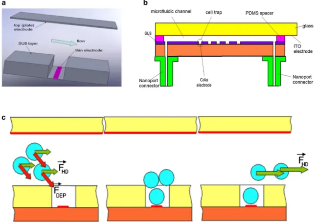
The architecture of the dielectrophoretic trap is illustrated in Fig. 1a, while a detailed picture with the structure of the device is presented in Fig. 1b. The top electrode consists of a thin indium tin oxide (ITO) electrode plate deposited on glass. The bottom electrode is a thin CrAu layer patterned on an insulated substrate. On the surface of this electrode, a SU8 layer is placed with a pattern that follows the elec-trode shape. A PDMS spacer, adhesive bonded on the top of the ITO electrode, defines the depth and the shape of the microfluidic channel. The difference in electrode dimen-sions assures a gradient of electric field across the micro-fluidic channel, generating a DEP force (eDEP effect). This DEP force is enhanced by the presence of the insulating structure—SU8 layer—(iDEP effect). These “double DEP” configurations assure an effective cell trapping with a low applied voltage, and as a consequence, a low Joule heating effect (Tay et al. 2007).
The cell patterning method is shown in Fig. 1c. The cells suspended in the DEP buffer are flown through the
Fig. 1 Device structure and cell patterning method using eDEP and
iDEP: a configuration of the microfluidic channel with electrodes and dielectric layer; b cross section with the cell patterning device; c cell
patterning method: The cells are trapped using a strong DEP force, and the hydrodynamic force removed the excess cells
microfluidic channel. Due to the strong DEP force, the cells are moving to the thin electrode placed in the hydrody-namic trap (positive DEP). It results in a 2D or 3D aggrega-tion of the cells in the trap (according to the cell size and trap dimension). By increasing the flow rate, the hydrody-namic force removes the cells placed on the top of the trap or on the top of the SU8 layer. The role of this insulating layer is not only to enhance the gradient of electric field, but also to act as a hydrodynamic cell trap, generating a “dead volume” where the velocity of the fluid is reduced. 2.2 Device fabrication
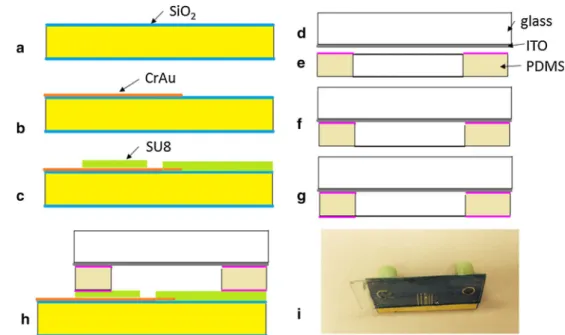
The device consists of two dies that are assembled together: • a silicon die with the thin electrode and the SU8
hydro-dynamic trap;
• a glass die having embedded the large ITO electrode. The fabrication of the silicon die starts with a 4″ double-polish wafer, <100> crystallographic orientation, with a resistivity of 1–100 Ω/cm. The wafer was cleaned in pira-nha (H2SO4/H2O2 in ratio 2/1) at 120 °C for 20 min, then washed in DI (deionized) water and spun-rinsed dried. A dry 150-nm-thick SiO2 layer was grown in a Tystar furnace at 1050 °C, for 3 h (Fig. 2a). A metal layer (Cr/ Au 30/400 nm) was deposited with an e-beam evapora-tor (CHA). A 2-µm-thick positive phoevapora-toresist (AZ7218 from Clarian) was deposited with a EVG 101 spin coater at 3000 rpm for 30 s. The film was exposed on a EVG 620 mask aligner and further developed. The metal layer was etched through the photoresist mask using com-mercially available Au and Cr etchants. In the next step,
the photoresist mask was removed in a NMP photoresist remover using ultrasonic agitation (Fig. 2b). In order to improve the adhesion of the SU8 layer to the substrate, a 50-nm-thick Teflon layer was deposited on the wafer in an ICP reactor (Alcatel) using C4F8. A 20-µm-thick SU8 2025 negative photoresist (for the definition of the hydrodynamic traps) was spin-coated on top of the Teflon layer at a speed of 4000 rpm and followed by a soft bake on a hot plate at 65 °C for 3 min and 95 °C for 6 min. Then, the SU8 was exposed on the EVG 620 mask aligner with constant expo-sure energy of 150 mJ/cm2. After that, a postexposure bake
at 65 °C for 1 min and 95 °C for 6 min was conducted, and the patterned SU8 was developed in SU8 developer and rinsed with isopropanol IPA. A short cleaning process of 1 min in O2 plasma on a RIE (SPTS) was used for remov-ing the Teflon layer and also to assure the clean surface of the electrode (Fig. 2c). The thickness of the SU8 layer was 20 µm. For the protection of the SU8 layer, the wafer was covered with a thick photoresist layer AZ4620 (~20 µm) before dicing of the individual chips on a DISCO 3350 equipment. Inlet and outlet holes were performed using a drilling machine with diamond beads.
For the second die, a glass wafer cover with ITO layer was diced on the same DISCO 3350 equipment (Fig. 2d). PDMS spacer was prepared by cutting the shape of the spacer from 75-µm-thick PDMS sheet (AAA ACME Rubber Co.). Curable PDMS elastomer kit: Sylgard 184 (Dow Corning) prepared in the ratio of 10/1 was spun on a dummy silicon wafer at 1000 rpm. A thin layer of cur-able PDMS was imprinted on the PDMS spacer (Fig. 2e) for the adhesive bonding between the ITO glass die and PDMS spacer (Fig. 2f). The curing of the soft PDMS was performed at 110 °C for 30 min.
Fig. 2 Main steps of the
fabri-cation process of the microflu-idic chip with dielectrophoretic– hydrodynamic traps: a growth of dry SiO2 (150 nm thick) on a silicon wafer, b deposition and patterning of the CrAu layer; c deposition and patterning of the SU8 layer and dicing of the Si wafer; d dicing of the ITO glass wafer; e cutting of the PDMS spacer and deposition of a thin PDMS adhesive layer on one surface; f adhesive bonding of the PDMS spacer on ITO glass;
g contact imprinting of a PDMS
layer on the PDMS spacer; h adhesive bonding between the ITO glass die (with the PDMS spacer) and silicon die; i photo-graph of the chip
The final bonding between the silicon and the glass dies was performed also using curable PDMS as adhesion layer. Similar to the method presented before, the curable PDMS was spun on a dummy wafer, and from this dummy wafer, a thin PDMS layer was imprinted on a Teflon cylinder and further transferred to the glass die (Fig. 2g). A simi-lar method used for SU8 adhesive bonding was described in details by (Yu et al. 2006). The glass and the silicon dies were placed in contact and bonded in the same con-ditions as the bonding of the PDMS spacer on ITO glass die (Fig. 2h). Nanoport microfluidic connectors (Upchurch) were attached on the chip using UV curable glue (NOA63 form Norland Products). An image with the fabricated chip is presented in Fig. 2i.
2.3 Cell culture and DEP buffer
C3A cells (ATCC, USA) were cultured in Dulbecco’s modified Eagle’s medium (DMEM) supplemented with 10 % FCS, 1.5 g/L sodium bicarbonate, 1 mM sodium pyruvate, 100 units/mL penicillin and 100 g/mL strepto-mycin. Red blood cells were isolated from whole blood by centrifugation and were resuspended in DEP buffer prior to experiment.
The dielectrophoretic buffer plays an important role in achieving the desired dielectrophoretic force. The DEP buffer was prepared by diluting 10 × TBE buffer (Promega Singapore) in deionized water and by adding 8.6 % (w/w) sucrose and 0.3 % (w/w) dextrose. The conductivity of the solution was 550 µS/m (measured with Oakton meter), while the pH was 7.
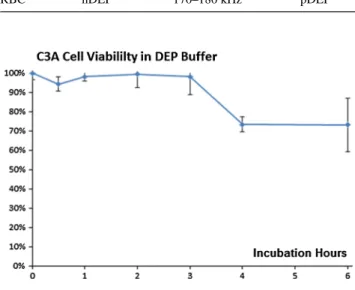
C3A cells were cultured in a 24-well plate until conflu-ence. On the experiment day, the cells were removed from the incubator and culture medium was changed once prior to the start of the experiment in order to remove dead cells. After trypsinization and centrifugation, the culture medium was replaced by the DEP buffer at their corresponding time point, so that the cells were incubated in the DEP buffer at room temperature for 6, 4, 3, 2, 1 and 0.5 h, respectively. At the end of the experiment, the cell viability was measured using MTS assay and compared against C3A cells cultured in medium at room temperature (i.e., 0 h of incubation in DEP buffer).
2.4 Testing setup
A digital microscope (Keyence VHX 500) was used to monitor the cell trapping inside the DEP device. The flow of the cells suspended in the DEP buffer was performed using a syringe pump (New Era Pump Systems Inc.). A function generator (TG210 from TTi) and a linear ampli-fier (A-303 from A.A Lab Systems Ltd) were used to gen-erate the drive signal applied to the DEP device. In order
to prevent the generation of bubbles inside the channel by electrolysis, prior flowing of the cell suspension into the microfluidic structure, the function generator and ampli-fier were powered on, but their outputs were set to the minimum.
3 Simulations and analytical model
3.1 Simulation of the electric field
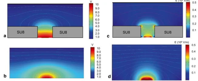
A simulation of the electric field is presented in Fig. 3
(using QuickField form Tera Analysis Ltd). For compari-son, variation of the applied voltage (10 V), the electric field and the gradient of the electric field were presented for the proposed structure (Fig. 3a, c) and also in the absence of SU8 layer (Fig. 3b, d). As it can be noticed from Fig. 3c, a very strong variation of the electric field is displayed around the SU8 corners, which proves the enhancement of the DEP force due to the insulating structure. The presence of the SU8 layer makes possible the trapping of the cells that are flowing at a certain distance from the thin electrode plane.
3.2 Simulation of the flow
For the flow inside the microfluidic channel, 2D simula-tions using the FLUENT™ CFD commercial package were performed in order to compute the isothermal flow of the Newtonian viscous fluids through the analyzed microgeom-etry. All the simulations considered steady laminar flows, double precision with convergence criteria of 10−10 for the
unknown functions and the continuity equation being used. The FLUENT™ code solves the Cauchy equation of motion in which the extra-stress tensor is expressed as a generalized Newtonian model:
where ρ is the fluid density (assumed constant), b the spe-cific mass force, D is the stretching, t is the time, u is the velocity vector, p is the pressure, and η( ˙γ ) is the viscosity function, dependent on the shear rate ˙γ. For a Newtonian fluid, η( ˙γ ) = η0 and Eq. (1) becomes the Navier–Stokes
equation, as the viscous term has the simplified expression η0�u.
The numerical code complements the equation of motion with the mass conservation equation, which, for incompressible fluids, is reduced to ∇ · u = 0. The compu-tational mesh has a total number of cells (NC) of 91,200. The validity of fluid homogeneity and the no-slip boundary condition were assumed for the tested fluid. The govern-ing equations above are solved numerically usgovern-ing a finite
(1) ρ ∂u
∂t + (u · ∇)u
volume method. In this methodology, the resulting alge-braic equations relate the dependent variables (p, u), which are calculated at the center of the cells forming the compu-tational mesh, to the values in the nearby surrounding cells. Because the interest in this work is for steady-state calcu-lations, the time derivative is discretized with an implicit first-order Euler scheme. The physical properties of the fluid used in the numerical calculations were selected to match water (η0 = 10−3 Pa s). The initial conditions to be
imposed were as follows: (1) no-slip conditions at the solid walls, (2) at the inlet boundary, located far upstream of the interest regions, a uniform velocity profile and a null stress components were imposed and (3) the imposed outflow boundary conditions involved vanishing stress components, respectively, a constant of gradient pressure (atmospheric pressure) was imposed at the channel outlet.
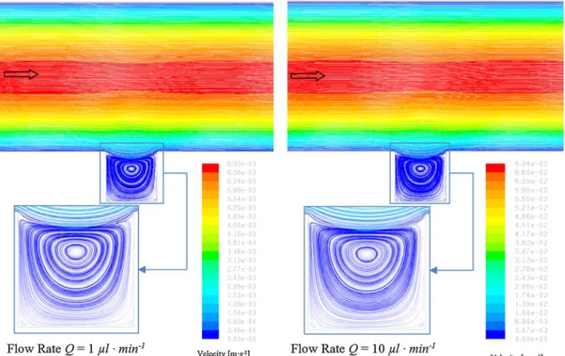
The numerical results for two different flow regimes (Q = 1 µL/min and Q = 10 µL/min) are presented in Fig. 4. For this range of velocity of the fluid, no difference in flow behavior and vortex structures can be observed.
3.3 Analytical model
The DEP buffer plays an important role in achieving the desired patterning using electric fields. The DEP force can be defined according to Jones (2005) as:
where Re[K] is the real part of the Clausius–Mossotti (CM) factor (also called “polarization factor”):
(2) FDEP= 2π a3Re[k]∇E2 (3) K = ε ∗ p− εm∗ ε∗ p+ 2εm∗ , ε∗= ε − jσ ω where ε∗
p and ε∗p are the complex permittivity of the
parti-cle and medium, respectively. The complex permittivity is a function of permittivity (particle or medium) ε, electri-cal conductivity σ and the angle frequency ω of the applied electrical field E. Depending on the sign of Re(K) (Albre-cht et al. 2005), the particles can be attracted to the regions with high electric field (so-called positive DEP–pDEP) or repelled—negative DEP (nDEP). In our case, the device structure requires the handling of pDEP effect.
Figure 5 gives a schematic of the microfluidic channel with a trapped cell. For low Mach numbers, the fluid can be considered as incompressible and its density is there-fore constant. Within the channel, and considering a no-slip boundary condition at the wall, the fluid velocity exhibits a parabolic profile that follows the Poiseuille equation:
with v(z) the fluid velocity across the channel and oriented along the x-axis, vmax its maximal value taken on the chan-nel axis and H the height of the chanchan-nel. The effect of the width of the channel is neglected. vmax is given by the
vis-cosity η0 and the pressure gradient dp/dx—assumed con-stant along the channel—as vmax = (H2/8η
0)dp/dx. The
effect of the traps at the bottom of the channel is difficult to take rigorously into account, especially because of the formation of vortices. Numerical simulations reveal that the laminar flow penetrates into the trap down to a depth δ. Below this penetration depth, the fluid is rotational, but the velocities are small compared to those in the channel. In the lower half of the channel above a trap, we consider that the Poiseuille flow still holds but extends up to z = H/2 + δ. As (4) v(z) = vmax 1 −4z 2 H2
SU8
SU8 1.0 2.0 3.0 4.0 5.0 6.0 7.0 8.0 9.0 10 V SU8 1.0 2.0 3.0 4.0 5.0 6.0 7.0 8.0 9.0 10 V a b 0.3 0.2 0.1 0.4 0.5 E (106 V/m) SU8 SU8 0.3 0.2 0.1 0.4 0.5 E (106 V/m) c dFig. 3 Variation of the applied voltage (a, b) electric field (c, d) across the vertical cross section of the microfluidic channel for the structure
a result, using the general Eq. (4), the flow velocity at the top of the trap reads
If the cells are not deeply buried into the trap, which is the case because we need an access to their surface for practical applications, they can feel the effect of the lam-inar flow in the channel. In particular, if δ is comparable
(5) vtrap= vmax 1 − H 2 (H + 2δ)2 ≈ 4vmax δ H
or greater than h − 2a, the difference of pressure between the interior of the trap and the laminar flow may untrap the cells yet maintained by the dielectrophoretic force. Accord-ing to Bernoulli’s principle, a heuristic upper limit for the lift force FL exerted on the cells is:
after replacing vtrap by its expression in (4). As we can see, the lift force scales as v2
max which means that the untrapping
rate increases rapidly with the flow velocity in the channel. Equilibrating the lift force (6) with the expression of the dielectrophoretic force FDEP yields a condition on vmax— and consequently on the flow rate—to keep the cells in the traps:
With a typical dielectrophoretic force FDEP of 1 nN
for a cell radius of 7.5 µm, a fluid density ρ = 1000 kg/ m3, a channel height H = 60 µm and a penetration depth
δ = 5 µm, the maximal fluid velocity should not exceed
0.16 m/s1, which corresponds to a flow rate of 15.3 µL/
min by integrating (4) over the cross section of the channel. Above this flow rate, the cells start to get untrapped.
(6)
FL = 2πρa2vtrap2 ≈ 32πρa2
δ H 2 vmax2 (7) vmax< H 4δ a ρRe[K]∇E 2
Fig. 4 Velocity in the microfluidic channel for flow rates of 1 and 10 µL/min
Fig. 5 Schematic of the microfluidic channel with a spherical cell
placed in a trap. v(z) is the fluid velocity, H the height of the channel,
h the height of the trap, a the cell radius and δ the flow penetration depth
4 Results and discussion
4.1 DEP buffer
As previously mentioned, due to thermic considerations (Iliescu et al. 2006b), a low electrical conductivity of the DEP buffer is required, the incremental temperature rise (ΔT) being approximated with the formula (Ramos et al.
1998):
where V is the applied voltage, and k is the thermal con-ductivity of the solution. It is well known that the tempera-ture modification can induce changes in the cell physiol-ogy (Cima et al. 2013; Lindquist 1986), and even if is not clear what is the range of temperature that induces a cell response, Joule heating effect must be minimized.
As it can be noticed from Eq. (3), the CM factor is a func-tion of frequency. The polarizability of the cell is a cumu-lative effect of its internal structure (Voldman 2006). As a result, each type of cell presents a “dielectrophoretic signa-ture” (Flanagan et al. 2008), signature that can be character-ized using the method proposed by (Voldman et al. 2003). Overall, as a general trend, at low-frequency range (up to 100 kHz), the cells are less polarizable and experience mainly negative DEP (nDEP)—the cells move toward the regions with lower field strength. For high-frequency range (1–100 MHz), the CM factor is given by the difference between cell cytoplasm and media conductivities, result-ing in nDEP for highly conductive solutions and positive (pDEP) in low conductive media (Voldman 2006). For the pDEP effect, the cells are moving to the regions with high field strength. In our case, for the trapping of the cells in the designed cage, we need a pDEP effect. As a result, low conductivity of the DEP buffer and an applied voltage in the MHz range are required in our application. In our case, the effect of frequency variation on C3A cells and RBC (sus-pended in the DEP buffer) is summarized in Table 1.
A second condition related to the buffer is its compatibil-ity in regard to the cells. For this reason, we used the proto-col previously described to verify the viability of the C3A cells in the DEP buffer up to 6 h. This duration is sensitively longer than the time frame required for DEP experiment (usually 1 h). The results presented in Fig. 6 shows that at least for the first 3 h, the viability of C3A cells due to the prolonged incubation in the DEP buffer will not be affected considerably. The testing method was described in Sect. 2.2. 4.2 Cell patterning
For the 3D cell patterning, RBCs and the previously mentioned DEP buffer were used. The average diameter
(8) �T ≈ σV
2
k
of RBCs is around 6 µm that allowed a 3D organiza-tion in the hydrodynamic trap (with a cross secorganiza-tion of 20 µm × 20 µm). In order to see the DEP effect, the cells were introduced in the microfluidic device, and at a flow rate of 7 µL/min, the cells were trapped using an applied voltage of 20 V at 1 MHz. The results are illus-trated in Fig. 7a. As it can be observed, the cells tend to attach also to the edge of the dielectric layer (where the gradient of electric field is strong). Increasing the flow rate in the microfluidic channel (at 30 µL/min) reduces sensitively the efficiency of trapping (Fig. 7b), only the cell in the vicinity of the SU8 layer is trapped. It is interesting to notice that the cells try to align near the walls of the hydrodynamic trap. This can be explained through the increasing gradient of the electric field on the corner of the CrAu electrode inside the hydrody-namic trap (Fig. 3e) and also due to the adhesion force (Mittal et al. 2007) between cell and SU8. It seems that the cell–substrate (SU8) adhesion force makes difficult a perfect removing of the cells from the SU8 surface by hydrodynamic force (Fig. 7a). Figure 7c shows the trapping of the RBC in a static regime. It can be noticed that in this case, the dipole–dipole interaction can play an important role. The polarization of the cells in the presence of the electric field induces an alignment of the cells in a row. Practically, in the absence of the flow, there is no “packaging” of the cells in the hydrodynamic trap. Figure 7d illustrates the evolution of RBC’s trap-ping in time, suggesting the organization of cells in a 3D structure. This “packaging” of cells can be explained
Table 1 Cell response to the frequency of applied electric field
Cell type DEP effect Cutting frequency DEP effect
C3A nDEP 7.6–8.2 kHz pDEP
RBC nDEP 170–180 kHz pDEP
through the dipole–dipole interaction. A dielectric par-ticle immersed in a medium and exposed to an electric field acquires a dipole moment. If a number of polarized particles come close enough to each other, they exhibit an attractive dipole–dipole interaction. This phenom-enon gives rise to a “pearl chain” alignment of the par-ticles and was previously used for aligning of different waterborne pathogen (Chow and Du 2011) or for elec-trofusion of lipid containers (Tresset and Iliescu 2007). In our case, confining the RBC’s (having a diameter of 6 µm) in a trap having a cross section of 20 × 20 µm
will enhance the dipole–dipole interaction between cells contributing to their “packaging” in a 3D structure. It is interesting to observe that initially the RBCs are align-ing along the edges (where high gradient of the electric field is expressed) and the walls of the trap.
Figure 8 illustrates cell patterning using C3A cell line. In this case, the diameter of the cell is almost identical with the width of the microfluidic trap. For the trapping of C3A cells, similar conditions were used. A very nice organiza-tion of the cells in the hydrodynamic trap can be observed (Fig. 8a). For comparison, conventional eDEP method was
Fig. 7 Cell patterning (RBC’s) under different flow conditions (a, b) and in a static regime (c). Evolution of RBC trapping in time (d). The
width of the hydrodynamic trapped fabricated in the SU8 layer was 20 µm
Fig. 8 Cell patterning using C3A cell line: a chip with the hydrodynamic trap; b trapping in the absence of the hydrodynamic trap (conventional
used for trapping C3A cells in Fig. 8b. Although the cells align mainly along the electrode, there is a significant num-ber of untrapped cells. Moreover, clustering of the cells due to dipole–dipole interaction is possible (and can be easily noted at the lower electrode). The removal of the untrapped cells and those attached on the bottom surface, using an increased flow rate, becomes more difficult, and the Stokes force also acts on the cells trapped using DEP. In this case, the adhesion force of the cell on the surface, estimated to be between 0.25 and 20 pN depending on the cell type and size (Mittal et al. 2007), is a strong competitor for the DEP force.
5 Conclusions
The paper proposes a DEP method for 2D–3D cell pat-terning. The architecture of the device consists of DEP– hydrodynamic traps placed in a microfluidic channel. A distinctive feature of the DEP structure is the combination between iDEP and eDEP effects for the generation of the dielectrophoretic force. The cells that are flown through a microfluidic channel are trapped in a hydrodynamic cage using cumulative iDEP–eDEP force, generating 2D or 3D cell patterns according to the ratio between cell dimension and the size of the cage. The trapping method was validated using C3A and red blood cells.
References
Albrecht DR, Tsang VL, Sah RL, Bhatia SN (2005) Photo- and elec-tropatterning of hydrogel-encapsulated living cell arrays. Lab Chip 5:111–118. doi:10.1039/b406953f
Albrecht DR, Underhill GH, Wassermann TB, Sah RL, Bhatia SN (2006) Probing the role of multicellular organization in three-dimensional microenvironments. Nat Methods 3:369–375 Albrecht DR, Underhill GH, Mendelson A, Bhatia SN (2007) Multiphase
electropatterning of cells and biomaterials. Lab Chip 7:702–709 Arora A, Simone G, Salieb-Beugelaar GB, Kim JT, Manz A (2010)
Latest developments in micro total analysis systems. Anal Chem 82:4830–4847
Bhadriraju K, Chen CS (2002) Engineering cellular microenviron-ments to improve cell-based drug testing. Drug Discov Today 7:612–620
Bhatia S, Balis U, Yarmush M, Toner M (1999) Effect of cell–cell interactions in preservation of cellular phenotype: cocultivation of hepatocytes and nonparenchymal cells. FASEB J 13:1883–1900 Birkbeck AL, Flynn RA, Ozkan M, Song D, Gross M, Esener SC
(2003) VCSEL arrays as micromanipulators in chip-based bio-systems. Biomed Microdevices 5:47–54
Čemažar J, Miklavcˇicˇ D, Kotnik T (2013) Microfluidic devices for manipulation, modification and characterization of bio-logical cells in electric fields—a review. Informacije MIDEM 43:143–161
Choi J-W, Rosset S, Niklaus M, Adleman JR, Shea H, Psaltis D (2010) 3-dimensional electrode patterning within a microfluidic channel using metal ion implantation. Lab Chip 10:783–788
Choudhury D, Mo X, Iliescu C, Tan LL, Tong WH, Yu H (2011) Exploitation of physical and chemical constraints for three-dimensional microtissue construction in microfluidics. Biomicro-fluidics 5:022203
Chow KS, Du H (2011) Dielectrophoretic characterization and trap-ping of different waterborne pathogen in continuous flow manner. Sens Actuators A 170:24–31
Cima I, Yee CW, Iliescu FS, Phyo WM, Lim KH, Iliescu C, Tan MH (2013) Label-free isolation of circulating tumor cells in microflu-idic devices: current research and perspectives. Biomicroflumicroflu-idics 7:011810
Di Carlo D, Aghdam N, Lee LP (2006) Single-cell enzyme concentra-tions, kinetics, and inhibition analysis using high-density hydro-dynamic cell isolation arrays. Anal Chem 78:4925–4930 Dittrich PS, Manz A (2006) Lab-on-a-chip: microfluidics in drug
dis-covery. Nat Rev Drug Discov 5:210–218
Flanagan LA, Lu J, Wang L, Marchenko SA, Jeon NL, Lee AP, Monuki ES (2008) Unique dielectric properties distinguish stem cells and their differentiated progeny. Stem Cells 26:656–665 Haeberle S, Zengerle R (2007) Microfluidic platforms for
lab-on-a-chip applications. Lab Chip 7:1094–1110
Higginbotham SN, Sweatman DR (2008) A combined travelling wave dielectrophoresis and impedance sensing device for sensing bio-logical cell suspensions. J Phys D Appl Phys 41:175503 Ho C-T, Lin R-Z, Chang W-Y, Chang H-Y, Liu C-H (2006) Rapid
het-erogeneous liver-cell on-chip patterning via the enhanced field-induced dielectrophoresis trap. Lab Chip 6:724–734
Hsiung L-C et al (2008) A planar interdigitated ring electrode array via dielectrophoresis for uniform patterning of cells. Biosens Bioelectron 24:869–875
Huang Y, Williams JC, Johnson SM (2012) Brain slice on a chip: opportunities and challenges of applying microfluidic technology to intact tissues. Lab Chip 12:2103–2117
Hwang H, Lee D-H, Choi W, Park J-K (2009) Enhanced discrimina-tion of normal oocytes using optically induced pulling-up dielec-trophoretic force. Biomicrofluidics 3:014103
Iliescu C, Xu GL, Samper V, Tay FE (2005) Fabrication of a dielec-trophoretic chip with 3D silicon electrodes. J Micromech Micro-eng 15:494–500
Iliescu C, Tay FE, Xu G, Yu LM, Samper V (2006a) A dielectropho-retic chip packaged at wafer level. Microsyst Technol 12:987–992 Iliescu C, Yu L, Xu G, Tay FE (2006b) A dielectrophoretic chip
with a 3-D electric field gradient. J Microelectromech Syst 15:1506–1513
Iliescu C, Xu GL, Loe FC, Ong PL, Tay FEH (2007) A 3 dimensional dielectrophoretic filter chip. Electrophoresis 28:1107–1114 Iliescu C, Xu GL, Barbarini E, Avram M, Avram A (2009a)
Microflu-idic device for continuous magnetophoretic separation of white blood cells. Microsyst Technol 15:1157–1162
Iliescu C, Tresset G, Xu G (2009b) Dielectrophoretic field-flow method for separating particle populations in a chip with asym-metric electrodes. Biomicrofluidics 3:044104
Ino K et al (2008) Cell culture arrays using magnetic force-based cell patterning for dynamic single cell analysis. Lab Chip 8:134–142 Ito A, Akiyama H, Kawabe Y, Kamihira M (2007) Magnetic
force-based cell patterning using Arg-Gly-Asp (RGD) peptide-conjugated magnetite cationic liposomes. J Biosci Bioeng 104:288–293
Iwasa J, Ochi M, Uchio Y, Katsube K, Adachi N, Kawasaki K (2003) Effects of cell density on proliferation and matrix syn-thesis of chondrocytes embedded in atelocollagen gel. Artif Org 27:249–255
Jen C-P, Huang C-T, Shih H-Y (2010) Hydrodynamic separation of cells utilizing insulator-based dielectrophoresis. Microsyst Tech-nol 16:1097–1104
Johann RM (2006) Cell trapping in microfluidic chips. Anal Bioanal Chem 385:408–412
Jones TB (2005) Electromechanics of particles. Cambridge Univer-sity Press, Cambridge
Khademhosseini A, Suh KY, Jon S, Eng G, Yeh J, Chen G-J, Langer R (2004) A soft lithographic approach to fabricate patterned micro-fluidic channels. Anal Chem 76:3675–3681
Khademhosseini A, Yeh J, Eng G, Karp J, Kaji H, Borenstein J, Farokhzad OC, Langer R (2005) Cell docking inside microwells within reversibly sealed microfluidic channels for fabricating multiphenotype cell arrays. Lab Chip 5:1380
Lewpiriyawong N, Yang C (2014) Continuous separation of multiple particles by negative and positive dielectrophoresis in a modified
H filter. Electrophoresis 35(5):214–220
Li S, Li M, Hui YS, Cao W, Li W, Wen W (2013) A novel method to construct 3D electrodes at the sidewall of microfluidic channel. Microfluid Nanofluid 14:499–508
Li M, Li W, Zhang J, Alici G, Wen W (2014) A review of microfabri-cation techniques and dielectrophoretic microdevices for particle manipulation and separation. J Phys D Appl Phys 47:063001 Lin RZ, Ho CT, Liu CH, Chang HY (2006) Dielectrophoresis
based-cell patterning for tissue engineering. Biotechnol J 1:949–957 Lindquist S (1986) The heat-shock response. Annu Rev Biochem
55:1151–1191
Manneberg O, Vanherberghen B, Svennebring J, Hertz HM, Önfelt B, Wiklund M (2008) A three-dimensional ultrasonic cage for char-acterization of individual cells. Appl Phys Lett 93:063901 Markx GH, Rousselet J, Pethig R (1997) DEP-FFF: field-flow
frac-tionation using non-uniform electric fields. J Liq Chromatogr Relat Technol 20:2857–2872
Martinez-Duarte R (2012) Microfabrication technologies in dielectro-phoresis applications—a review. Electrodielectro-phoresis 33:3110–3132 Masuda S, Washizu M, Nanba T (1989) Novel method of cell fusion
in field constriction area in fluid integration circuit. IEEE Trans Ind Appl 25:732–737
Mittal N, Rosenthal A, Voldman J (2007) nDEP microwells for single-cell patterning in physiological media. Lab Chip 7:1146–1153 Mo X et al (2010) Rapid construction of mechanically-confined
multi-cellular structures using dendrimeric intercellular linker. Biomaterials 31:7455–7467
Morimoto Y, Takeuchi S (2013) Three-dimensional cell culture based on microfluidic techniques to mimic living tissues. Biomater Sci 1:257–264
Nasabi M, Khoshmanesh K, Tovar-Lopez FJ, Kalantar-zadeh K, Mitchell A (2013) Dielectrophoresis with 3D microelectrodes fabricated by surface tension assisted lithography. Electrophore-sis 34:3150–3154
Neužil P, Giselbrecht S, Länge K, Huang TJ, Manz A (2012) Revisit-ing lab-on-a-chip technology for drug discovery. Nat Rev Drug Discov 11:620–632
Ni M, Tong WH, Choudhury D, Rahim NAA, Iliescu C, Yu H (2009) Cell culture on MEMS platforms: a review. Int J Mol Sci 10:5411–5441
Nilsson J, Evander M, Hammarström B, Laurell T (2009) Review of cell and particle trapping in microfluidic systems. Anal Chim Acta 649:141–157
Pethig R (2010) Review article—dielectrophoresis: status of the the-ory, technology, and applications. Biomicrofluidics 4:022811
Pethig R, Talary MS, Lee RS (2003) Enhancing traveling-wave die-lectrophoresis with signal superposition. IEEE Eng Med Biol Mag 22:43–50
Piggee C (2009) Optical tweezers: not just for physicists anymore. Anal Chem 81(1):16–19
Ramos A, Morgan H, Green N, Castellanos A (1998) Ac electroki-netics: a review of forces in microelectrode structures. J Phys D Appl Phys 31:2338
Rosenthal A, Voldman J (2005) Dielectrophoretic traps for single-par-ticle patterning. Biophys J 88:2193–2205
Skelley AM, Kirak O, Suh H, Jaenisch R, Voldman J (2009) Micro-fluidic control of cell pairing and fusion. Nat Methods 6:147–152 Sun T, Morgan H (2010) Single-cell microfluidic impedance
cytom-etry: a review. Microfluid Nanofluid 8:423–443
Suzuki M, Yasukawa T, Shiku H, Matsue T (2008) Negative dielectro-phoretic patterning with different cell types. Biosens Bioelectron 24:1043–1047
Taff BM, Desai SP, Voldman J (2009) Electroactive hydrodynamic weirs for microparticle manipulation and patterning. Appl Phys Lett 94:084102
Tan WH, Takeuchi S (2007) A trap-and-release integrated microflu-idic system for dynamic microarray applications. Proc Natl Acad Sci USA 104:1146–1151
Tay FE, Yu L, Pang AJ, Iliescu C (2007) Electrical and thermal char-acterization of a dielectrophoretic chip with 3D electrodes for cells manipulation. Electrochim Acta 52:2862–2868
Tresset G, Iliescu C (2007) Electrical control of loaded biomimetic fem-toliter vesicles in microfluidic system. Appl Phys Lett 90:173901 Voldman J (2006) Electrical forces for microscale cell manipulation.
Annu Rev Biomed Eng 8:425–454
Voldman J, Toner M, Gray M, Schmidt M (2003) Design and analy-sis of extruded quadrupolar dielectrophoretic traps. J Electrostat 57:69–90
Wang L, Lu J, Marchenko SA, Monuki ES, Flanagan LA, Lee AP (2009) Dual frequency dielectrophoresis with interdigitated side-wall electrodes for microfluidic flow-through separation of beads and cells. Electrophoresis 30:782–791
Wong I, Ho C-M (2009) Surface molecular property modifications for poly (dimethylsiloxane) (PDMS) based microfluidic devices. Microfluid Nanofluid 7:291–306
Wu J et al (2011) A sandwiched microarray platform for benchtop cell-based high throughput screening Biomaterials 32:841–848 Xing X, Zhang M, Yobas L (2013) Interdigitated 3-D Silicon ring
microelectrodes for DEP-based particle manipulation. J Micro-electromech Syst 22:363–371
Yang M, Li C-W, Yang J (2002) Cell docking and on-chip monitoring of cellular reactions with a controlled concentration gradient on a microfluidic device. Anal Chem 74:3991–4001
Yeo LY, Hou D, Maheshswari S, Chang HC (2006) Electrohydrody-namic surface microvortices for mixing and particle trapping. Appl Phys Lett 88:233512
Yeo LY, Chang HC, Chan PP, Friend JR (2011) Microfluidic devices for bioapplications. Small 7:12–48
Yu L, Tay FE, Xu G, Chen B, Avram M, Iliescu C (2006) Adhesive bonding with SU-8 at wafer level for microfluidic devices. J Phys Conf Ser 34:776–780
Zhang S et al (2011) A robust high-throughput sandwich cell-based drug screening platform. Biomaterials 32:1229–1241