READ THESE TERMS AND CONDITIONS CAREFULLY BEFORE USING THIS WEBSITE. https://nrc-publications.canada.ca/eng/copyright
Vous avez des questions? Nous pouvons vous aider. Pour communiquer directement avec un auteur, consultez la
première page de la revue dans laquelle son article a été publié afin de trouver ses coordonnées. Si vous n’arrivez pas à les repérer, communiquez avec nous à PublicationsArchive-ArchivesPublications@nrc-cnrc.gc.ca.
Questions? Contact the NRC Publications Archive team at
PublicationsArchive-ArchivesPublications@nrc-cnrc.gc.ca. If you wish to email the authors directly, please see the first page of the publication for their contact information.
NRC Publications Archive
Archives des publications du CNRC
This publication could be one of several versions: author’s original, accepted manuscript or the publisher’s version. / La version de cette publication peut être l’une des suivantes : la version prépublication de l’auteur, la version acceptée du manuscrit ou la version de l’éditeur.
Access and use of this website and the material on it are subject to the Terms and Conditions set forth at
On using multiple Kij's in the EN12354 acoustics prediction model to
represent excess attenuation in flanking surfaces
Nightingale, T. R. T.; Bosmans, I.
https://publications-cnrc.canada.ca/fra/droits
L’accès à ce site Web et l’utilisation de son contenu sont assujettis aux conditions présentées dans le site LISEZ CES CONDITIONS ATTENTIVEMENT AVANT D’UTILISER CE SITE WEB.
NRC Publications Record / Notice d'Archives des publications de CNRC:
https://nrc-publications.canada.ca/eng/view/object/?id=08ad8f6e-c75b-4c8e-adfb-6dee945f9b0c https://publications-cnrc.canada.ca/fra/voir/objet/?id=08ad8f6e-c75b-4c8e-adfb-6dee945f9b0cOn using multiple Kij’s in the EN12354 acoustics
prediction model to represent excess attenuation in
flanking surfaces
Nightingale, T.R.T.; Bosmans, I.
NRCC-44991
A version of this document is published in / Une version de ce document se trouve dans
Proceedings of the 17th International Congress on Acoustics, Rome, Italy, Sept. 2-8, 2001, pp. 1-2 www.nrc.ca/irc/ircpubs
On using multiple K
ij
’s in the EN12354 acoustics prediction
model to represent excess attenuation in flanking surfaces
Trevor RT Nightingale
aand Ivan Bosmans
ba
Institute for Research in Construction, National Research Council, Ottawa, Ontario, Canada K1A OR6
b
CSTB, 24, rue Joseph Fourier, 38400 Saint-Martin-d'Hères, France
EN12354 is a standardised method to compute the apparent sound insulation of building assemblies formed by wall and floor elements that are assumed to be heavy, monolithic, homogeneous and moderately damped. However, most large walls and floors are not perfectly homogeneous, they are made by joining together a series of smaller more manageable pieces, (e.g., precast concrete, plasterboard, glass panes, etc.). Depending on the mechanical properties of the joints between panels, there may be significant excess attenuation, which in most cases indicates the surface must be treated as a series of connected panels. This summary paper shows that EN12354 is based on simplified SEA and can be extended to account for excess attenuation introduced by junctions between the elements. However, the effective Kij necessary to account for the excess attenuation is not simply the sum of the Kij’s for all junctions, as this leads to significant errors.
INTRODUCTION
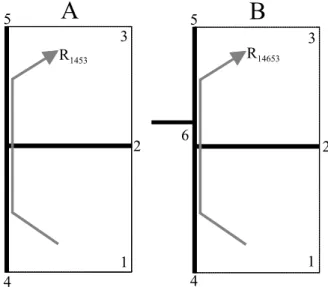
The EN12354 [1] prediction models allow for one junction or attenuating element in the flanking path which permits estimation of the flanking sound reduction for most paths. The path 1453 of Figure 1A is one example. Recently, situations have been presented [2], similar to that shown in Figure 1B for path 14653, where a small element (shown as 6) couples a larger element (5) to the junction. In this case there are two junctions (4-6 and 6-5) in the path each causing vibration attenuation. It has been suggested [2] that excess attenuation due to multiple junctions could be represented by an effective vibration reduction index, K*ij, which is simply the sum the Kij’s
for the two, or more, junctions of the flanking path.
1 2 3 4 R1453 5 R14653 5 3 1 4 6 2
A
B
FIGURE 1. Two rooms 1 and 3 separated by wall 2. In Figure 1A the flanking walls 4 and 5 do not have a coupling element, while in Figure 1B they are coupled by element 6.
This paper provides a derivation based on the principles of SEA to show that for the case of multiple junctions it not possible to sum the vibration
attenuation of all the junctions in the flanking path as, in general, this will lead to serious errors.
THEORY
Using SEA [3] the sound reduction index (SRI) for an arbitrary transmission path is,
+ = E A E E D D C C B B A ABCD A V S V E E E E E E E E R 10log 10log (1)
where E is the energy in the subsystem, V is the room volume, S is the partition area separating the two rooms, A is the absorption in the receive room, and the subscript identifies the element in the transmission path.
Using equation 1, and a number of approximations and assumptions, the EN12354 expression for the SRI of a flanking path involving a single junction (equation 25 in Ref. 1) can be obtained. A detailed discussion is beyond the scope of this summary paper and will be presented elsewhere; instead the procedure is summarised as follows. The energy stored by each subsystem is expressed in terms of the ratio of the total loss factor to coupling loss factor, and using reciprocity with several substitutions, the expressions for path 1453 can be written as,
+ + + = 45 54 5 4 5 4 2 2 5 4 1453 5log 10log 2 η η η η S S S R R R (2)
while the corresponding expression for path 14653 involving two junctions is,
+ + + = 56 65 46 64 6 5 6 4 5 4 2 2 5 4 14653 5log 10log 2 η η η η η η η η S S S R R R (3)
where Ri is the resonant sound reduction index for the
element i when measured in-situ. By inspection of equations 2 and 3 it can be seen that the basic formulations are identical excepting the last terms which account for junction attenuation. Thus, it would appear that multiple junctions can be accommodated by modifying the junction term. It must be noted that terms involving element 6 appear only in the
description of the junction, consequently element 6 is assumed not to radiate energy. Thus, element 6 is referred to as being a coupling element.
The junction terms of equations 2 and 3 can be described by the velocity level difference, VLD, of the connected elements and their mass, using,
+ = j i ij v ij j M M D 10log log η , η 10 (4)
Reciprocity that was used in writing equation 2 greatly simplifies the junction terms as they reduce to the direction averaged VLD,
D
v,ij, between the connected plates i and j. The term for a single junction becomes,45 , 54 , 45 , 45 54 5 4 2 log 10 v v v D D D = + = η η η η (5) S 10 while the expression for two junctions becomes,
65 , 46 , 65 , 56 , 64 , 46 , 56 65 46 64 6 5 6 4 2 2 log 10 v v v v v v D D D D D D + = + + + = η η η η η η η η (6)
EN12354, expresses the vibration attenuation at the junction in terms of a vibration reduction index, Kij, which is the direction averaged VLD normalised to
the length of the junction, lij, and an “equivalent
absorption length”, a, of each connected element,
j i ij o ij v ij a a l l D K = , −10log (7)
For framed elements, ones with a high internal loss factor, or ones which are considerably lighter than the elements to which it is connected, EN12354 assumes that a, can be approximated by the surface area of the element, S, divided by unit length, lo. Using this and
substituting equation 7 into 5 gives the EN12354 (Part 1, equation 25) result for a single junction,
+
+
+
=
45 2 45 5 4 145310
log
2
l
l
S
K
R
R
R
o (8)while the corresponding expression for two junctions is, + + + + + = 65 6 65 46 2 46 5 4 14653 log 10 log 10 2 l l S K l l S K R R R o o (9)
For the sake of simplicity in the following discussion we shall assume that the length of all the junctions are the same, l, which is often the case for walls. If the expression applicable to a single junction as given in EN12354 (i.e., equation 8 above) were to be extended to allow for two junctions with a coupling
element then the effective junction vibration reduction index,
K
45* , would be, + + = o l l S K K K 6 65 46 * 45 10log (10)
DISCUSSION
Equation 10 indicates that in general the Kij’s
can not simply be summed since there is an additional term involving the area of coupling element 6 and the junction length. In most cases, element 6 will be a rectangular with the length of one side equal to the coupling length l, and the other side equal to w. Consequently, the error can be approximated by:
( )
w l l o log 10 log 6 ≈ (11)The assumption of summing Kij’s may underestimate
the SRI when the width, w, is greater than 1 metre and overestimate when the width is less than 1 metre.
Although it might be tempting to sum the Kij’s
and apply a correction term equal to equation 11, it should be stressed that the expressions given in equations 9, 10 and 11 are only valid when element 6 satisfies the conditions necessary for a SEA plate subsystem. This requires that element 6 support enough modes in both principal directions so that the modal overlap factor exceeds unity, and that the vibration be dominated by the reverberant field (that is the response should be reasonably diffuse).
When element 6 is a narrow strip, these fundamental and necessary conditions are most likely not satisfied and any form of an effective Kij should not
be applied at all. In this situation, one should treat both junctions and the intermediate element as a single coupling element characterised by a single Kij.
In the derivation of equations 9, 10 and 11, it was assumed that the sound radiated by element 6 would be small with respect to element 5 which is coupled to it. However, for situations where element 6 satisfies the conditions of an SEA subsystem, it is very likely that radiation will be significant and it may be necessary to compute the SRI of paths 1463, in addition to 14653.
The derivation shows that EN12354 is based on simplified SEA where there is only one junction, consequently care must be given to ensure that all elements satisfy the requirements of an SEA subsystem.
REFERENCES
[1] Anon, EN12354, Estimation of acoustic performance of buildings
from the performance of elements, Parts 1 and 2, 1997.
[2] Schumacher, Rolf, and Sas, Bernd, Journal of Building Acoustics,
6, No.3/4, pp. 309-340 (1999).
[3] Craik, Robert J M, Sound transmission through buildings using