Publisher’s version / Version de l'éditeur:
Vous avez des questions? Nous pouvons vous aider. Pour communiquer directement avec un auteur, consultez la
première page de la revue dans laquelle son article a été publié afin de trouver ses coordonnées. Si vous n’arrivez pas à les repérer, communiquez avec nous à [email protected].
Questions? Contact the NRC Publications Archive team at
[email protected]. If you wish to email the authors directly, please see the first page of the publication for their contact information.
https://publications-cnrc.canada.ca/fra/droits
L’accès à ce site Web et l’utilisation de son contenu sont assujettis aux conditions présentées dans le site LISEZ CES CONDITIONS ATTENTIVEMENT AVANT D’UTILISER CE SITE WEB.
Report (National Research Council of Canada. Division of Building Research), 1957-09-01
READ THESE TERMS AND CONDITIONS CAREFULLY BEFORE USING THIS WEBSITE.
https://nrc-publications.canada.ca/eng/copyright
NRC Publications Archive Record / Notice des Archives des publications du CNRC :
https://nrc-publications.canada.ca/eng/view/object/?id=e21597a2-1c66-46a1-9c5b-e53a1b5c6fe5 https://publications-cnrc.canada.ca/fra/voir/objet/?id=e21597a2-1c66-46a1-9c5b-e53a1b5c6fe5
NRC Publications Archive
Archives des publications du CNRC
For the publisher’s version, please access the DOI link below./ Pour consulter la version de l’éditeur, utilisez le lien DOI ci-dessous.
https://doi.org/10.4224/20337972
Access and use of this website and the material on it are subject to the Terms and Conditions set forth at
Periodic Heat Flow in Walls and Roofs
NATIONAL RESEARCH COUNCIL OP CANADA
DIVISION OF BUILDING RESEARCH
PERIODIC HEAT FLOW IN WALLS AXD ROOFS
by
D. G. Stephenson
Report No. 132 o f the
Division of Building Research
OTTAWA
PREFACE
The D i v i s i o n of B u i l d i n g Research i s c u r r e n t l y r e - examining and a p p r a i s i n g t h e methods employed i n p r e d i c t i n g t h e t h e r m a l energy exchange between t h e indoor and t h e o u t d o o r environment t h r o u g h t h e e n c l o s i n g w a l l s and r o o f s of buf l d i n g s , Summer c o n d i t i o n s which g i v e r i s e t o p e r i o d i c flow a r e o f
s p e c i a l i n t e r e s t , and h e a t exzhange between t h e ground s u r f a c e and t h e outdoor e n v i ~ o n m e n t i s a l s o of' c o n c e r n o
Although t h e p a t h of the t h e r m a l energy exchange between i n d o o r s and outdoorca may be broken i n t o p a r t s f o r s p e c i a l study, t h e s e a r e a c t u a l l y i n t e r - r e l a t e d and i n a r i g o r o u s t r e a t m e n t must be c o n s i d e r e d t o g e t h e r
,
I t became n e c e s s a r y i n d e a l i n g w i t h the exchange between e x t e r i o rs u r f a c e s and t h e outdoor environment t o c o n s i d e r a l s o c e r t a i n a s p e c t s of the h e a t f l o w through t h e b u i l d i n g e n c l o s u r e i t s e l f , One a s p e c t of t h i s , t h e e a s e o f p e r i o d i c h e a t flow i n walls and r o o f s , and o f methods by which it may be c a l c u l a t e d i s now
c o n s i d e r e d , C e r t a i n a s p e c t s of t h e t h e r m a l exchange between t h e e x t e r i o r s u r f a c e o f a b u i l d f n g and t h e outdoor environment were d e a l t w i t h i n DBR Report Moo 1210
It i s n o t a p p a r e n t t h a t t h e m a t e r i a l c o n t a i n e d i n t h i s r e p o r t w i l l be of s u f f i c i e n t i n t e r e s t t o o t h e r s t o w a r r a n t
pub11 c a t i o n , Opinions on t h f s, t o g e t h e r wf t h a n y c r f t i c i s m and o t h e r comments a r e invf t e d ,
Ottawa
September 195'7,
N o B o Huteheon
PERIODIC HEAT FLOW
IN
WALLSAND
ROOFSD.
G. StephensonABSTRACT
-
llrwo methods of calculating the periodic heat flow
through a d i d walls or roofs are described. The matrix
method gives the accurate value of heat flow through a solid wall whether homogeneous or multilayer. One of the advantages of this method is the ease with which different surface heat transfer coefficients can be accounted for.
A
much simpler vector diagram method is presented for calcula-ting the complex thermal impedance of a wall or roof. The errors which occur with this method are chiefly due to
representing a continuous wall by a lumped resistance-
capacitance network. 'Ilhe lumping error for a "T" network representation of a homogeneous wall is evaluated analy-
tically: the same method can be applied to more complex
circuits.
The following is the nomenclature used in this
paper.
c + i d = sinh (1
+
i) i@ q(1 + ill" n
an = harmonic phase angle
Anp Bn9 On and Dn = elements of wall matrix for heat wave of frequency n
= outside air film coefficient of heat
transfer
= inside air film coefficient of heat transfer
=
J
-1= thermal conductivity of wall material
= thickness of homogeneous wall or of
= frequency of temperature wave in cycles per day
= heat flux across outside surface of
wall or roof
= heat flux across inside surface of
wall or roof
harmonic component of q2 with frequency n = sol-air temperature
43
= inside air temperature
=
24
hour average of sol-air temperature= harmonic component of T1 with frequency n
= thermal impedance of continuous wall
for a heat wave of frequency
n
= t17n/ when T2 = constant
9 2 ,n
= thermal diffusivity of wall material
= dimensionless number characteristic
of wall or wall element
r - n
8 = hours after noon
a',
= harmonic lag angleA n = harmonic decrement factor
When primes are added to any of the above listed quantities, it indicates that the value is appropriate for
a lumped resistance capacitance network. The number of
The h e a t f l o w t h r o u g h t h e walls o r r o o f of a b u i l d i n g r a r e l y r e a c h e s a s t e a d y s t a t e , s o f o r a n a c c u r a t e c a l c u l a t i o n o f h e a t i n g o r c o o l i n g l o a d it i s n e c e s s a r y t o t a k e a c c o u n t o f t h e h e a t s t o r a g e c a p a c i t y of t h e w a l l o r r o o f . Nackey
and Wright (1, 2 ) have r e p o r t e d a n a c c u r a t e and approximate
method f o r c a l c u l a t i n g t h e p e r i o d i c h e a t f l o w t h r o u g h
.homogeneous and m u l t i l a y e r walls. T h e i r work w a s based on
t h e f o l l o w i n g assumptions : (1) P e r i o d i c s o l - a i r t e m p e r a t u r e ( 2 ) Constant i n d o o r a i r t e m p e r a t u r e ( 3 ) The o u t d o o r a i r f i l m c o e f f i c i e n t o f h e a t t r a n s - f e r , hl, i s 4.0 B . ~ . U . / ~ ~ ~ hr FO ( 4 ) !be i n d o o r a i r f i l m c o e f f i c i e n t o f h e a t t r a n s f e r , h2, i s 1.65 B . ~ . u . / ~ ~ z hr
( 5 )
One dimensional h e a t f l o w t h r o u g h t h e w a l l These g i v e t h e h e a t f l u x a c r o s s t h e i n n e r s u r f a c e asThe decrement f a c t o r A n and t h e l a g a n g l e $ifn a r e g i v e n
k
g r a p h i c a l l y as f u n c t i o n s o f
-
and k . p .c. The e q u a t i o n s Lr e l a t i n g t h e s e f a c t o r s t o t h e w a l l p a r a m e t e r s a r e i n c l u d e d s o t h a t t h e v a l u e s may be c a l c u l a t e d f o r o t h e r v a l u e s o f t h e f i l m c o e f f i c i e n t s . The work r e q u i r e d t o o b t a i n
r n
and%
f o r o t h e r v a l u e s o f hl o r hp i s c o n s i d e r a b l e even f o r ahomogeneous w a l l , and much more f o r a composite w a l l . I n
t h e f o l l o w i n g s e c t i o n s two a l t e r n a t i v e p r o c e d u r e s a r e des- c r i b e d . The m a t r i x method g i v e s a n e x a c t s o l u t i o n w i t h
l e s s work t h a n t h e Mackey and W r i g h t method; and t h e v e c t o r
diagram g i v e s a v e r y good approximation f o r r e l a t i v e l y l i t t l e c o m p u t a t i o n a l work.
Equation (1) can be w r i t t e n a s
where
qmean
-
-
tm
-
'P2in the terms used by Nackey and
Vlright
.
2
, is here called the wall thermal impedance
l,UTRIX METHOD OF 03TAINIXG WALL THERTlXG IMPEDANCE
Van Gorcum
(3)
has shorn that for periodic tempera-ture oscillations the temperature and heat flux at each
surface of a homogeneous slice of material are related by
a linear transformation where a An = cosh (1
+
i) ?$: n Bn =%,
sinh (1+
i)p n
(1 + i) l n-
(1 + i)Pn.
...
Cn-
7 3 sinh (1+
i) (0, (9)*
Van Gorcum expressed the matrix elements by trigonometricrather than hyperbolic f'unctions but there is no real difference.
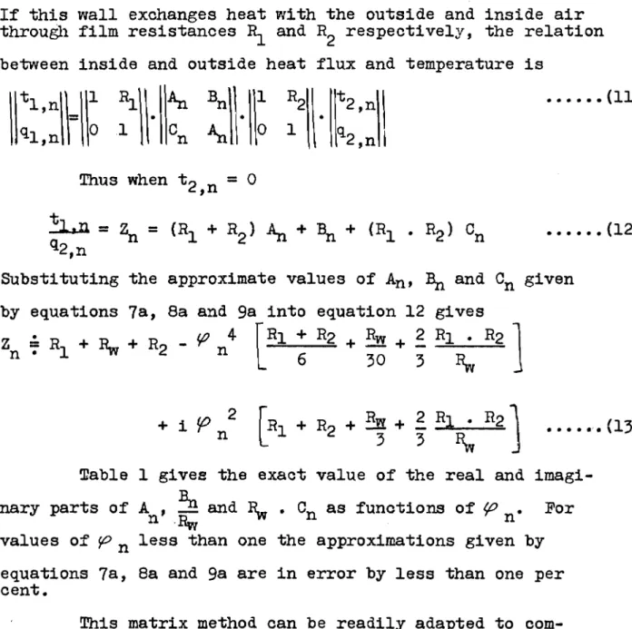
If this wall exchanges heat with the outside and inside air through film resistances
5
and R respectively, the relation 2 between inside and outside heat flux and temperature isThus when t
2,n = 0
Substituting the approximate values of An,
B,
and Cn given by equations7a,
8a and 9a into equation 12 givesr
-
Table 1 givee the exact value of the real and imagi- nary parts of
A
!!?!
and%
.
Cn as functions of (o For"'
R,values of p n less than one the approximations given by equations 7a, 8a and 9a are in error by less than one per cent.
'Phis matrix method can be readily adapted to com- posite walls since eaoh layer of the wall can be represented by a four-term matrix. !Phe matrix for the composite wall is just the product of the matrices for each component; v i z :
for a two-layer wall. The impedance formula is slightly different in this case because the wall matrix contains four different terms
The example calculation in Appendix
I
illustrates the method and incidentally sko\vs the difference in the impedance of the wall when the order of the layers is reversed. The calculation of the matrix elements for homogeneous layers of a wall is simple, but for a composite wall the matrix multiplication requires considerable computation. However,when the matrix elements for a wall have-been detemined -
it is a very simple matter to calculate the wall thermal
impedance for any values of the inside and outside air film
coefficients of heat transfer. The matrix elements for the more common composite walls and roofs could be~tabulated
in the ASHAE ~uide.
A
Vector Diagram Method of Obtaining Flail !Thermal ImpedanceThe example calculation in Appendix I shows that
considerable computation is involved in obtaining the
exact impedance for a multilayer mall, The effort required
to obtain this accurate value of the im~edance is often not
justifiable because of the large possibie errors in the thermal constants assumed for the wall materials, For
such circumstances a veotor diagram solution is much easier and quicker to obtain.
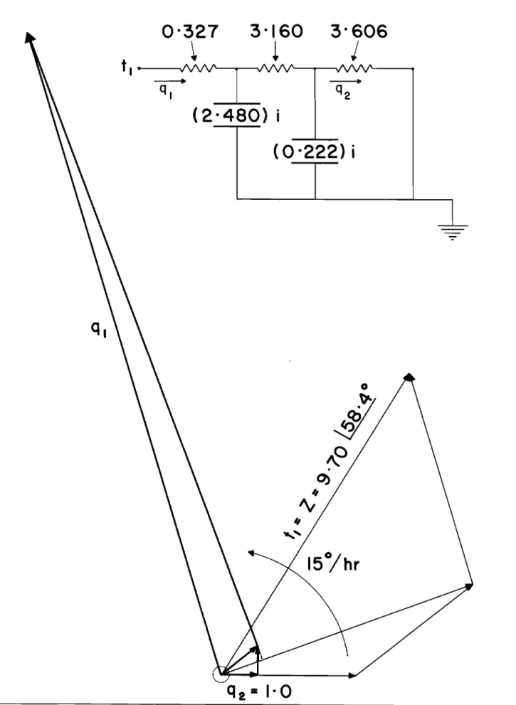
IlZle wall is first represented by a lumped resistance-
capacitance network and then the temperatures and heat fluxes at the various points are determined. As an illustration, a thin homogeneous wall will be considered, The wall can
be represented by a "T" network, and the inside and outside
film coefficients by resistors which are in series with the wall network. The input temperature tl,, which will cause a unit output flux is equal to the wall thermal impedance '
n The output heat flux q ~ is represented by the unit , ~
vector along the X axis in Fig. 11. The temperature at
the centre of the wall is ( L
+
1 ) and in phase with the2E
5
output heat flux, The heat flux representing the heat
stored in the wall is 90' ahead of the temperature at the
centre of the wall and has a magnitude ( 2 n n
.
L. p , c. ).
(+
6).
, The heat flux across the outside surface ofthe wall is the vector sum of the heat output and the heat stored. The input temperature equals the vector sum of
1
the mid wall temperature plus
(K
+
L , times the heat fluxA
into the wall. This outside temperature vector represents
For a multilayer wall each layer can be represented
by a
T
network and the wall by the combination ofT
networksin series, with the film resistors at each end of the circuit.
The procedure for such a composite wall is just the same
as for the simple T described above. At each network nodal
point the heat flux representing the heat stored in the
lump is go0 ahead of the temperature at that same point.
The heat flow toward a nodal point is the vector sum of the
heat flowing arvaa- and being stored. The temperature
difference between nodal points is in phase with the heat flow. Tlie total temperature drop is the vector sum of the differences beC,veen each of the nodal points. Figures
111, IT, V, and VI are accurate diagrams for the com2osite
wall considered in Appendix
I.
Errors in the Vector '~iagram Procedure
The impedance obtained by constructing a vector
diagram differs from the correct value for two reasons,
namely :
(1) Errors due to inexact construction of the diagram
(2) Errors due to representing a continuous wall by a lumped resistance-capacitance network.
m e errors can be evaluated separately since the exact value
of impedance can be calculated for a continuous li~all and
for a lumped network.
Tne matrix for a T network representatioa of a wall
element is
2
1
1
+
iPn2,
L
(1+
is,'*K
-
2j
Thus, for a
T
network representation of a homogeneous walltaking account of the surface films,
2
1.0 1
When Zn as given by equation (13) is subtracted from ZA
the difference is the error due to lumping
-
-
For a 4-in. concrete wall
so that Z1 = 1.037
+
i (0.601) = 1,199 130.1'Thus the lumping error is
5
per cent on1
Z1( and-
2 percent on the argument,
'Ihe vector diagram, Figure 11, gave 2' = 1.260
2 . 0 , thus the error due to construction of tfte diagram
is less than
0.5
per cent.Summary
!The matrix method will give an accurate value of wall thermal impedance for a solid wall of any number of
layers. The only assumptions necessary are: (1) sol-air temperature and inside air temperature are periodic;
(2) the inside and outside air film coefficients of heat
transfer are constant with respect to time;
(3)
the heatflow through the wall is one dimensional. Once the wall matrix has been determined the wall thermal impedance can be easil calculated for any values of the inside and
-h9
outsi e air filn coefficients of heat transfer. This is
the chief advantage of this method compared to that of
blackey and Wright, Considerable computation is required to
find the matrix for a composite wall; thus it would be
desirable to have tabulated in the ASHAE Guide the matrix
elements for the more common wall types.
The vector method is much simpler than the matrix method for multilayer walls if the matrix elements have to be calculated. The error in the vector diagram method is
resistance-capacitance network. This error can be reduced by using more lumps. In the example considered in Appendix
I
there was an error of 10 per cent when each layer of awall was represented by a
T
network, and of about 1.5 percent when each layer was represented by a ?r network.
In addition to giving the over-all wall thermal impedance, the vector diagram method gives values of heat flux and temperature at several points through the wall. References
1. Mackey, C.O. and L.T. Wright Jr., Periodic heat flow
-
homogeneous walls or roofs, Trans. A.S.H.V.E.,
vole
50,
1944, p. 293.2. Mackey, C.O. and L.T. Wright Jr., Periodic heat flow
-
composite walls or roofs, Trans. A.S.H.V.E., Vol. 52,
1946,
P*
283.3. Van Gorcum, A,H., Theoretical considerations on the
conduction of fluctuating heat flow, Applied Scientific Research, Vol. A2, 1951, p. 272.
-
1 0-
TABLE I ' n 0.00 0.10 0.20 0.30 0.40 0.50 0 4 6 0 0.70 0.80 0.90 1 - 0 0Values of t h e S p e c i a l Functions Needed
f o r C a l c u l a t i n g Wall Matrix Elements
cosh (l+i)
p
Real 1 0000 1.
0000 0.9997 0.9986 0.9958 0.9896 0,9784 0.9600 0.9318 0.8908 0.8337 Imaginary 0 0000 0.0100 0.0400 0.0900 0.1600 0.2498 0.3595 0.4887 0.6371 0.8041 0.9889 s i n h (l+i)P
n Real 1.0000 1.0000 0.9999 0.9997 0.9991 0.9979 0.9957 0.9920 0.9863 0.9782 0.9667(l+i )
p
,sinh (l+i n ( l + i ) p n Imaginary 0.0000 0.0033 0.0133 0.0300 0.0533 0.0833 0.1200 0.1632 0.2129 0.2692 0.3318 Real 0.0000 -0.0007 -0.0011 -0.0054 -0.0170 -0.0416 -0.0864 -0.1599 -0.2725 -0.4361 -0.6635 I Imaginary 0.0000 0.0200 0.0800 0.1799 0.3197 0.4990 0.7169 0.9722 1.2625 1.5846 1.9334TABLE 2
I
Comparison of Vector Magram and Analytical Results
4
in. concrete wall with 2 in.insulation "Tn metwork for each layer II It Network for each layer Accurate values Insulation Outside Insulation Inside ModZl 15.1 14.0 13.8 M o d Z1 9.70 8.90 8.80 ArgZ1 7g0 79.4O 79.2' k g Z 1 58' 57O 56.4'
Problem: Find the thermal impedance of a 4-in. concrete wall with 2-in. insulation
(a) on the inside of the concrete (b) on the outside of the concrete
Given :
R1
= 0.167 ft2.hr.I?"/~.t.u.R2
= 0.606 II = 0.320 1I Rconcrete = 6.000 It Rinsul. l2 concrete = 0.3975Solution: The matrix for the concrete is
!he elements of the composite wall matrix for the case of
insulation inside are
and the matrix for the insulation
A1
= AcAi
+
Bc Ci = 0.611+
i (1.087)B1
=A,
Bi+
BcAi
= 5.492 + i (3.902)C1 = co
A,
+ A, Ci = 2.099+
i (2.278)= Cc
Bi
+ Ac =-4.620+
i (15.266)Check A1 Dl
-
B1
C1 = 1.000-
i (.015), since this is a4
Bi
,Ci
a,
passive network the determinant of the matrix should be unity'.
-
-
0.926+
i (0.667),5.910
+
i (1.333)Thus
Mod Z1 = 8.80
A r g Z1 = 56.4'
For t h e c a s e w i t h i n s u l a t i o n on t h e o u t s i d e o f t h e c o n c r e t e t h e w a l l m a t r i x i s
T h i s same problem i s s o l v e d by t h e v e c t o r diagram procedure i n F i g u r e s 111, I V , V and V I and t h e r e s u l t s compared w i t h t h o s e c a l c u l a t e d above i n Table 2.
Periodic Heat Plow in Walls and Roofs
D.
G. StephensonF i g u r e Captions
Fig.
I
T network representation of a homogeneous wallwith inside and outside film resistances.
Fig. I1 Vector diagram for a T network representation of
a homogeneous wall with inside and outside film resistances.
Eg.111 Vector diagram for a two-lump representation of a 4-in. concrete wall with 2 in. insulation on inside of concrete.
Pig. IV Vector diagram for a two-lump representation of
a 4-in. concrete wall with 2 in. insulation on outside of concrete.
Fig. V Vector diagram for a four-lump representation
of a 4-in. concrete wall with 2 in. insulation
on inside of concrete.
M g . VI Vector diagram for a four-lump representation of
a 4-in. concrete wall with 2 in. insulation on outside of concrete.