HAL Id: hal-01175591
https://hal.archives-ouvertes.fr/hal-01175591
Submitted on 10 Jul 2015
HAL is a multi-disciplinary open access
archive for the deposit and dissemination of
sci-entific research documents, whether they are
pub-lished or not. The documents may come from
teaching and research institutions in France or
abroad, or from public or private research centers.
L’archive ouverte pluridisciplinaire HAL, est
destinée au dépôt et à la diffusion de documents
scientifiques de niveau recherche, publiés ou non,
émanant des établissements d’enseignement et de
recherche français ou étrangers, des laboratoires
publics ou privés.
Distributed under a Creative Commons Attribution - ShareAlike| 4.0 International
License
The Yoyo-Man
Jean-Paul Laumond, Mehdi Benallegue, Justin Carpentier, Alain Berthoz
To cite this version:
Jean-Paul Laumond, Mehdi Benallegue, Justin Carpentier, Alain Berthoz. The Yoyo-Man.
Interna-tional Symposium on Robotics Research (ISRR), Sep 2015, Sestri Levante, Italy. �hal-01175591�
Jean-Paul Laumond, Mehdi Benallegue, Justin Carpentier and Alain Berthoz
Abstract The Yoyo-Man project is a research action tending to explore the synergies of anthropomorphic locomotion. The seminal hypothesis is to consider the wheel as a plausible model of bipedal walking. In this paper we report on preliminary results developed along three perspectives combining biomechanics, neurophysiology and robotics. From a motion capture data basis of human walkers we first identify the center of mass (CoM) as a geometric center from which the motions of the feet are organized. Then we show how rimless wheels that model most passive walkers are better controlled when equipped with a stabilized mass on top of them. CoM and head play complementary roles that define what we call the Yoyo-Man.
1 Introduction: legs versus wheels?
Goal oriented motion is a distinguished character of living beings. A stone does not move by itself. Within the living systems, displacement is what makes the differ-ence between plants and animals. Animals make use of fins in the water and wings in the air. On land, apart from exceptions as crawling snakes, most of the animals are equipped with legs. Legged locomotion is based on rotating articulated limbs. The rotation of the limbs around the contact points on the ground transfers the body from a position to another one. Rotation then appears as a solution to translate an ar-ticulated body. If nature applies this principle to legged animals, it is surprising that
Jean-Paul Laumond, Mehdi Benallegue, Justin Carpentier
LAAS CNRS, Univ. de Toulouse, UPS, 7 avenue du Colonel Roche, F-31400 Toulouse, France e-mail: {jpl, mehdi.benallegue, justin.carpentier}@laas.fr
Alain Berthoz
Coll`ege de France - 11, place Marcelin Berthelot - 75231 Paris Cedex 5, France e-mail: [email protected]
it does not push this principle until the wheel discovery. Wheel has been invented
and developed by humans1. Our cars are equipped with wheels and not with legs.
The magic of the wheel is to transform a rotational motion into a translational one as soon as the wheel touches the ground. In this paper we intend to reveal the presence of a virtual wheel as condensing all the apparent complexity of the bipedal locomotion.
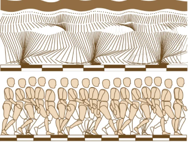
The motivation is twofold. From a biomechanics and neuroscience perspective we want to explore the synergies of human locomotion: how the walking body re-veals motion invariants beyond the well-known arm-leg coordination (Figure 1)? From a robotics perspective [Wieber et al., 2015] we seek to fill the gap between two opposite approaches of humanoid locomotion control. The most robust one is based on the control of the center of pressure between the feet and the ground al-lowing humanoid robots to walk on rough terrains. The second approach is based on clever mechanical designs that take advantage from the gravity. In the latter case the locomotion is much less energy consuming; however it is very fragile with respect to the ground perturbations.
The Yoyo-Man project intends to contribute to new mechanical and control de-signs for bipedal walkers inspired both by a better understanding of human walking and by the current research on passive walkers.
Fig. 1 From a chronophotographic image by E.J. Marey: Walking is a complex process involv-ing the actuation and the motion coordination of many body segments. What does motion capture reveal on the underlying synergies?
Figure 2 illustrates the rationale underlying the project. The rationale is twofold. From a mechanical perspective, a wheel rotating at the extremity of a string (i.e., a yoyo) induces its own translation as soon as it touches the ground. Legs are made 1The statement has to be nuanced: rotating engines exist at molecular scale and some insects are
of three rotating segments (foot, shank and thigh). A first question is addressed in Section 3: is there a locomotion geometric reference center to describe the motion of the foot independently from the motion of the shank and the thigh? On the other hand, from a neuroscience perspective, it is known that humans stabilize their head while walking. The second question we address in Section 4 is the following one: is there some mechanical benefit to equip passive walkers with a stabilized head on the top of them, i.e. a locomotion control center?
Fig. 2 The Yoyo-Man: The hand controls the height of the rotating wheel. The wheel translates as soon as it touches the ground. The Yoyo-man is a human walker model made of the geometric center of a virtual rotating wheel together with a control center located at the head.
2 Origins of the rationale
2.1 Mechanical basics of bipedal walking
Anthropomorphic systems are made of a tree of articulated rigid bodies linked to-gether by rotational joints. This is true for all humanoid robots. This is also true for human at first glance, if we neglect mechanical scapula or kneecap subtleties. Joint positions define the system posture. The system configuration is made of all the joints together with the three placement parameters that give respectively the position and the orientation of the system on the ground. From a control viewpoint, muscles or motors operates in the posture space. There is no direct control of the three placement parameters. In that sense, humans and humanoid robots are under-actuated systems. What is called locomotion is the process that modifies the posture of the system in such a way the reaction forces with the ground induce the variation of placement parameters.
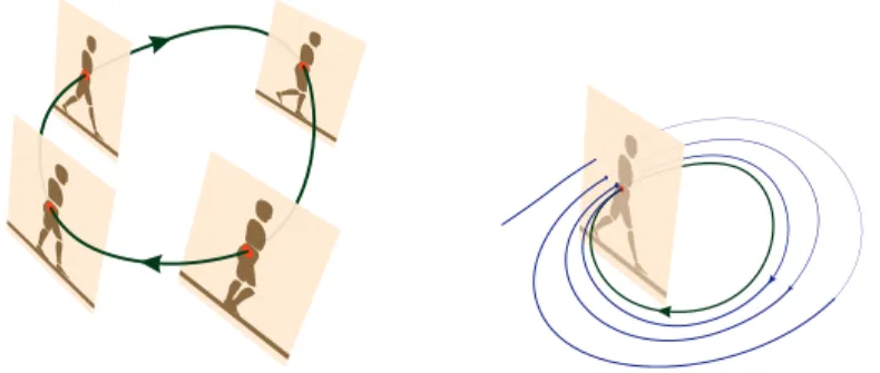
Bipedal walking is a cyclic process sequencing two phases: single support when only one foot is touching the ground and double support when both feet are touching the ground. This physical description holds for all bipedal walking systems. The cycle of locomotion is then made of four phases after which it starts again from
(almost) the same starting posture. The stability of the locomotion is reflected by the attractiveness of a periodic orbit called limit cycle. It is captured by the so-called Poincar´e map [Goswami et al., 1997]. In our context, the Poincar´e map is the intersection of the orbit of the periodic walking motion with the posture space at a same instant of the cycle, e.g., when the left foot touches the ground (Figure 3).
Fig. 3 Locomotion cycle: Locomotion is a cyclic process sequencing the same postures alterna-tively (left). The stability of the underlying dynamical system is captured by the Poincar´e map (right).
2.2 Basics in humanoid robot control
At each phase of the cycle the pressure applied by the surface of feet on the ground may be concentrated onto a single point: the center of pressure. When both the ground and the feet surfaces are flat, the center of pressure coincides with the so-called zero moment point (ZMP) introduced in [Vukobratovi´c, 1972]. As soon as the ZMP remains within the support surface, the system does not fall.
The property of the ZMP is at the origin of a popular locomotion control scheme. The ZMP and the center of mass (CoM) are linked together by nonlinear equations. The control of the CoM is easily derived from the control of the posture. So, in theory, it is possible to control the placement of the ZMP within the surface sup-port. However the nonlinearities linking CoM and ZMP variables make the problem computationally challenging. Under some hypothesis the equations are linear and the problem becomes easier. This is the case when the center of mass remains at the same altitude. Maintaining the CoM at the same altitude is made possible thanks to the redundancy of the anthropomorphic body. The hypothesis is at the origin of the cart-table model introduced in [Kajita et al., 2003] (Figure 4). The foundations of such control schemes are based on the knowledge of the foot steps to be performed. The literature refers to the so-called preview control [Wieber, 2008]: locomotion consists in planning the foot placement in advance.
Fig. 4 Cart-table: The cart-table model works under the hypothesis that the CoM moves on a horizontal plane. The hypothesis can be applied to control the locomotion of humanoid robots (left). Figure 1 suggests it does not hold for humans (right).
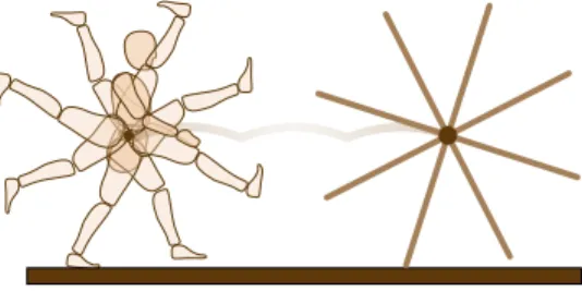
Passive walkers are designed from a completely different control perspective [Collins et al., 2005]. They are minimally actuated. The mechanical design is devised to take advantage of the gravity and to convert potential energy into kinetic energy. In its simplest version, the passive walker is made of two articulated legs connected to the hip [Collins et al., 2001]. It can be modeled as a compass whose gaits induced a motion of the hip that is the same as the motion of the center of a rimless wheel. At that stage, it is noticeable that the motion of the center of a rimless wheel seems to be a rather good approximation of the hip motion in human walking (Figure 5). The analogy is part of the Yoyo-Man project rational.
Fig. 5 Rimless wheel: At a first glance, the center of a rolling rimless wheel roughly accounts for the motion the hip.
2.3 Neurophysiology basics in human walking
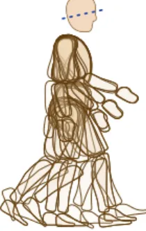
Neurophysiologists have observed that humans and animals stabilize their head when moving (see an illustration in Fig. 6). Head stabilization facilitates the fu-sion of visual and vestibular information. It offers a consistent egocentric reference
frame for motion perception for locomotion [Pozzo et al., 1990]. In the Yoyo-Man project we argue that head stabilization also contribute mechanically to the balance when walking. In depth description of the sensory cognitive benefits of head sta-bilization and preliminary results about its mechanical advantages are presented in Section 4.
Fig. 6 Sketch of the superimposition of walker positions in different phases of the cycle. The superimposition is achieved so that the head is in the same position. The head is stabilized to keep constant orientation displayed by the dotted blue line. (Inspired by a drawing in [Pozzo et al., 1990])
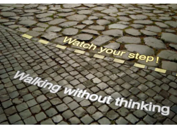
Do humans plan their steps in advance? Sometimes, they obviously do, when the ground is too uneven. However most of the time, they walk without thinking, i.e. without consciousness of any planning phase computing in advance where they have to place their feet. How does walking in the street differ from walking on a mountain path? On the top part of the pavement depicted by Figure 7, we have to anticipate what stones will next be used for stepping. On the other hand, walking on the pavement at the bottom part of the figure does not require any anticipation of the foot placements. In which context do we start watching our steps? Section 4.4 addresses the question by introducing the notion of ground texture.
3 In search of a geometric center for the Yoyo-Man
This section brings to light the geometrical similarity between the rimless wheel and the human body during walking (Figure 5). While rolling on the floor, the center of the rimless wheel describes a sequence of circle arcs whose radius correspond to the stand beam. From a local viewpoint, this statement can be rephrased as follows: the contact point describes an arc of circle around the center of the rimless wheel during each supporting phase. In the case of human body, does there exist such a link between the foot touching the ground and some point that plays the role of the center of some rimless wheel? As far as we know, this question has never been addressed in human motion modeling. At first glance, the articulation point between
Fig. 7 Pavement in Roma: two textured grounds. In the bottom part, we walk without thinking, in the upper part, one has to watch his/her steps.
the thighbone and the pelvis, i.e. the hip center, would be a good candidate to play the role of the locomotion geometric center. This is not the case. In this section, we show both that the proposed rimless wheel model holds for human walkers, and that the center of the rimless wheel is the center of mass (CoM) of the walking body.
3.1 Experimental setup
The experimental setup is based on an existing motion database used in [Olivier et al., 2011]. It is composed of 12 participants (5 women and 7 men, 32.8 ± 5.9 years old, 1.71 ± 0.09 m, 65.3 ± 10.1 kg) who have been asked to walk straight at three different speeds three times each: natural, slow, and fast walking speed. Sub-jects were equipped with 41 reflective markers, with a standard markers placement allowing to compute the center of mass trajectory by means of anthropomorphic tables [Dumas et al., 2007]. Finally, the segmentation of gait into simple et dou-ble support phases was achieved by using the methodology described in [Fusco and Cr´etual, 2008].
In our study, we are interested by natural locomotion. So, from the database we extracted the trials dealing with natural velocity. The the total number of analyzed trajectories is 12 × 3 = 36.
3.2 Identification of the foot-CoM relationship
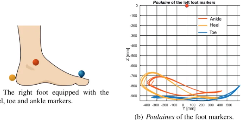
Poulaine2is a French word designating the trajectory of the anatomic feet markers
(e.g. ankle, heel, toe) relatively to the geometric center of the pelvis and expressed in the world frame. For instance, Figure 8 illustrates the poulaines of the heel, toe and ankle markers respectively.
(a) The right foot equipped with the heel, toe and ankle markers.
Ankle Heel Toe
Z [mm]
Y [mm] Poulaine of the left foot markers
-400 -300 -200 -100 0 100 200 300 400 500 -900 -800 -700 -600 -500 -400 -300 -200 -100 0
(b) Poulaines of the foot markers.
Fig. 8 Illustration of the right foot equipped with the heel, toe and ankle markers and Poulaines of those markers along 888 steps. None of the poulaines describes a circular path rela-tively to the pelvis center.
At the first sight, none of the aforementioned anatomic markers describes a
cir-cular trajectory relatively to the pelvis center3. At most, some poulaines have a
temporally (i.e. during a short period) a constant curvature, but not during all the stance phase. Our approach consists in moving the reference frame from the hip joint center to the CoM. We then show that a particular convex combination of the heel, ankle and toe markers of the stance leg describes a circular trajectory whose center is very close to the center of mass itself.
Choosing the CoM as the center of the reference frame and considering a con-vex combination of the toe, ankle and heel markers are supported by the following rationale. Firstly, the shift from the root marker to the center of mass allows us not to consider one precise segment (i.e. the root) but to take into account the overall movement of the human body. Secondly, by choosing a convex combination of the three aforementioned markers, we ensure that this particular point has an almost
zero velocity during the stance phase4. It can therefore be treated as the pivot point
of the rimless wheel.
2We did not find the exact translation of this word in English.
3In biomechanics, the pelvis center is considered as the root node from which the body segment
tree is built.
4It is worth to mention at this stage that, due to the rolling of the foot on the ground, there is no
3.3 Methodology
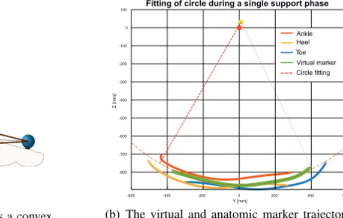
Each walking trial is composed of 10 steps. We divided each of these trials into phases of single and double support phases. Then we introduce a virtual marker at the convex combination of toe, ankle and heel markers by selecting a particular con-vex combination for each subject, we fitted in the least-square sense the best circle passing through this virtual marker during 85% of the single support phase. On av-erage, the root mean square error of the fitting part was around 2.5 mm. Figure 9 illustrates the procedure by showing the fitted circle having a center (yellow marker) very close to the CoM (red marker) and passing on average by the convex combi-nation (in green). The other curves correspond to the anatomic markers of the foot, the hip joint center and the pelvis center.
(a) The virtual marker as a convex combination of the anatomic foot markers.
Z [mm]
Y [mm]
Fitting of circle during a single support phase
Ankle Heel Toe Virtual marker Circle fitting -600 -400 -200 0 200 400 600 -800 -700 -600 -500 -400 -300 -200 -100 0 100
(b) The virtual and anatomic marker trajectories and the fitted circle.
Fig. 9 The virtual marker location and its trajectory relative to the CoM. The virtual marker (i.e. the convex combination of heel, toe and ankle markers) follows a circle whose center (yellow point) is close to the CoM (red point).
3.4 Results
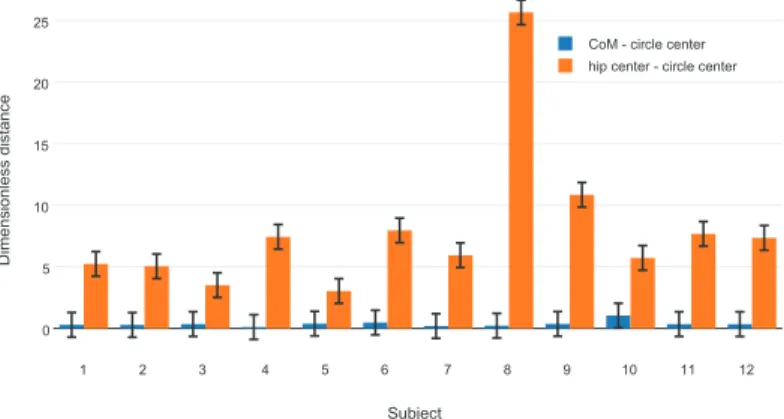
For each subject, we computed the covariance matrix of the set of circle center posi-tions relative to either the center of mass or the hip joint center. From the inverse of both covariance matrices, we define two distance metrics centered on the mean posi-tion of the circle centers and relative to the both reference points: the center of mass and the hip joint center. At the end, we obtained two dimensionless distances which discriminate if the two reference points belong to the circle center distributions or not.
Figure 10 summarizes the study over the 12 subjects. For the two metrics, the bar errors plotted at the top of each orange or blue boxes of Fig. 10 corresponds to the confidence interval [−1; 1]. While the height of the boxes corresponds to the dimensionless distance between either the center of mass or the hip joint center and the circle center distributions. We can remark that for all subjects, the CoM lives in the confidence interval of the circle center distributions. It is never the case con-cerning the hip joints center. Those observations allow us to conclude as following: first, there exists a similarity between the rimless wheel and humans during nom-inal walking gait and second, the center of this rimless does not correspond to the geometric pivot center (i.e. the hip joint center) but rather to the center of mass itself.
1 2 3 4 5 6 7 8 9 10 11 12 0 5 10 15 20 25 Subject Dimensionless distanc e
CoM - circle center hip center - circle center
Fig. 10 Dimensionless distance between the fitted circle centers and the CoM or the hip joint center. For all subjects, the center of mass belongs to the distribution of circle centers. This is not true in the case of the hip joint center.
Finally, it is worth mentioning that our results hold only in the case of nominal gaits (i.e. walking gait with natural comfort velocity). Indeed, in the case of slow or fast walking velocities, we found that there is no convex combination of markers belonging to the stance foot which has a circular path. Some other studies have been focused on formulating a generic model describing the center of mass trajectory for a large class of walking speeds [Hayot et al., 2013]. Nonetheless, the proposed model overestimates the vertical displacement of the center of mass while it fits well lateral motions.
4 In search of a control center for the Yoyo-Man
4.1 A convenient center of control
One important property of the human steady gait dynamics is that it takes profit from the natural passive dynamics of the body. The passive dynamics is the dynamics of
the body when no actuation is present, the robot is then subject only to gravity, ex-ternal forces and passive elasticity and friction of the joints. The body morphology (especially the hip and knee joints [Collins et al., 2001]) allows the emergence of most prominent features of walking dynamics. The benefits of this structure is to enable the generation of walking motion with high energy efficiency and low con-trol frequency [Alexander, 2005]. Furthermore, the concon-trol of steady gait has been investigated to suggest that it happens in a very low level of the brain, in a spinal level, consisting in a combination of a simple rhythm generator and reflexes to exter-nal perturbations [Dietz, 2003]. The steady gait seems to require minimal muscular efforts and cognitive involvements: we walk without thinking about it.
However, as we said earlier, neurophysiologists have observed that humans sta-bilize actively their head when moving, including walking on flat surfaces. By stabi-lization, we mean that the head tilt is controlled to remain relatively constant com-pared to other limbs of the body. Head stabilization is a task prone to dissipate en-ergy since it works almost always against the motion. So why do humans stabilize their head?
The head carries most of the sensory organs, and specifically the visuo-vestibular system, responsible for a great part of balance estimation, spatial localization and motion perception. It can be understood then that stabilizing the head facilitates the fusion of visual and vestibular information. Recent studies show also that head stabi-lization improves the accuracy of estimation of vertical direction by vestibular-like inertial sensor [Farkhatdinov et al., 2013]. Head stabilization improves perturbation detection and safety supervision. Moreover, head tilt conservation offers a consis-tent and stable egocentric reference frame for perception and generation of motion in general [Berthoz, 2002] and locomotion in particular [Pozzo et al., 1990, Hicheur et al., 2005].
These explanations fit with clinical observations on humans. The unsteadiness and the loss of balance resulting from head-neck system sensorimotor disturbances have been widely documented [Stokell et al., 2011, Lajoie et al., 1996, Bove et al., 2002, Vuillerme et al., 2005]. It has even been suggested that the impairments in the neck somatosensory inputs and sensorimotor control are as important for balance as a lower-limb proprioception loss following a knee or an ankle injury [Treleaven, 2008].
Therefore, we can consider that the head is the convenient center of locomotion control: even when we happen to walk without thinking, it offers a comfortable frame with stable dynamics and there takes place the perception, the cognition and the generation of gait.
However, the head is a relatively rigid limb, representing 7% of the total mass of the body, and occupies the top 12% of its height. That means a non-negligible deal of the inertia lies in there. Therefore, head stabilization which actively modifies the motion of the head, should have a noticeable impact on the dynamics of the gait. This effect may be negative, perturbing the walking dynamics and requiring the rest of the body to compensate for it. Alternatively it can be part of the desired dynamics, enhancing balance and improving coordination. In few words: does the head-stabilization by itself contribute to war effort against falling?
4.2 The model of steady-gait head-body dynamics
Based on mechanical concepts from passive robot walkers [Collins et al., 2005, Byl and Tedrake, 2009], we introduce a walking simulation scheme where two sim-ple walking mechanical models are then compared. These models include improve-ments to classical compass-like walkers, by adding torso, interleg actuation, spring-damper at the feet, and rough terrains.
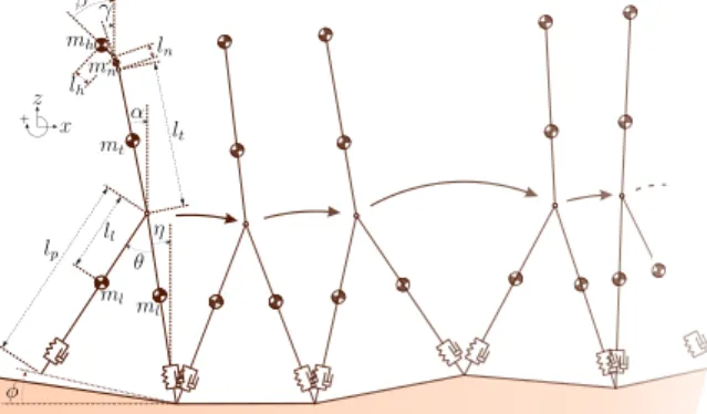
Figure 11 illustrates our mechanical model. It operates in the sagittal plane. It is made of five articulated rigid bodies: two bodies for the (knee-free) legs, one body for the torso, one for the neck and one for the head. Note that the neck is modeled as an articulated body and not as a simple joint. This setting reflects the property of the head-neck system to have two centers of rotation in the sagittal plane: one at the base of the neck and the other at ear level [Viviani and Berthoz, 1975]. The mass distribution and the limb lengths are anthropometric (e.g., [Armstrong, 1988]). In the first of our two models, the walker has a rigid neck and tends to stabilize the torso upright. In the second one the neck is modeled as a limb of two joints and the walker tends to maintain the head direction constant. Both walker models are inspired by the mechanical design of passive walking robots [Collins et al., 2005].
+
Fig. 11 A representation of the models we simulate. The A model is the same structure subject to the constraints α = β = γ. The B model has stabilized neck joints. The rough terrain is modeled with a slope change at each step.
Indeed, we do not aim at modeling perfectly the human gait. Up to now, only simple dynamical models allow to reproduce locomotion gaits [Mombaur, 2009]. Dynamical modeling of human walking is out of reach of all current simulators. Nevertheless the energy efficiency of these robots, the low-frequency of their con-trol and their natural limit-cycle dynamics are common characteristics with human locomotion [Alexander, 2005, Goswami et al., 1997].
Detailed technical description of the models is presented in [Benallegue et al., 2015 report].
4.3 Estimating balance: ground textures and MFPTs
Due to difference in control, the whole body dynamics of the walkers is different. However, both dynamics are balanced on flat surface and converge to a stable limit cycle. Therefore both walkers can walk indefinitely on flat surface without falling. However, the difference between the dynamics should lead to a difference in bal-ance performbal-ances. This difference should appear in the presence of external per-turbations. In our context the perturbation we study is ground texture, because it is still today a challenging problem, especially for passive-dynamics walkers.
A textured ground is a ground for which the unevenness follows a probability dis-tribution. For our 2D walker, we model it by changing the ground inclination at each step, following a centered Gaussian law. The standard deviation of the probability distribution define the degree of ground unevenness (see Figure 11).
[Byl and Tedrake, 2009] present a metrics which is particularly suitable for limit cycle walkers on uneven ground. This metrics is derived from classical analysis of metastable systems and is called Mean First Passage Time (MFPT). Limit-cycle walking is then considered as a metastable system, and MFPT is the mean number of steps the walker makes before falling. This metrics has the property to explore all the reachable dynamics of the walker subject to perturbations, to take into ac-count the repetitive property of ground texture, and to provide a synthetic estimator easy to comprehend intuitively. However, the computation of MFPTs may be time consuming using a naive approach, especially for good performance walkers. To solve this problem, we developed then an optimized algorithm to compute MFPT in reasonable time for complex walking systems [Benallegue and Laumond, 2013].
We computed then MFPTs for both models on several ground textures. And we present the results hereinafter.
4.4 Results
On flat terrain, and for both control models, it has not been possible to find an upper bound on MFPTs (see Fig. 12). However walker performances greatly differ as soon as a slight texture change appears. The phenomenon can be seen from the example of 0.01 rad standard deviation. In this case, MFPT of the rigid neck model is 23 steps, while head stabilization guarantees MFPT of more than 3 million steps! This performance improvement persists as the ground texture increases, even if the difference declines. This is purely due to mechanical effects, i.e. to the contribution of the head motion to the balance of the gait.
These results may be seen differently. The head stabilization curve of Fig. 12 can be seen as a shift to the right for the rigid neck curve. In other words, head stabilization enables to increase significantly the range of ground textures the walker can handle with the same balance performances.
As this level we may conclude that head stabilization may improve substantially the dynamic balance of walking systems. Head stabilization is an heuristic answer to
the question of taking advantage of the head mobility during walking. Indeed, while it is likely not the optimal control of the neck regarding balance, it is a very simple control that produces a complex behavior with significant benefits. Additional ex-planations for the origin of this effect, including its impact on energy consumption can be found in [Benallegue et al., 2015 report].
0 0.02 0.04 0.06 0.08 0.1 10 0 10 2 10 4 10 6
Ground texture (rad)
Mean number of steps
Head stabilization Rigid neck
Fig. 12 Mean number of steps with an ideal orientation sensor. Mean number of steps of the walker models equipped with an ideal orientation sensor on different textures of the ground. By texture we mean the standard deviation of the ground slope. MFPTs are displayed in logarithmic scale. For higher ground roughness, MRPT of both models drops such that they need to change their walking control: watching their step becomes necessary.
5 Conclusions
The preliminary results presented in this paper supports the intuition that bipedal walking can be understood as a wheel rotating around a fixed point (the CoM) while being controlled by a stabilized mass on top of it (Figure 2). What we introduced as the Yoyo-Man model then appears as a promising route to explore both to elucidate the synergies of the human locomotion and to design new mechanical and control architectures for humanoid robots. Here are the current research directions we are exploring:
• First, we have seen that the rotating rimless wheel model is a rather good model of human locomotion as soon as the center of the wheel is located at the center of mass, and surprisingly not at the joint between the hip and the thighbone. The result holds in the sagittal plane. However the model of the foot we have introduced from the three markers on the heel, the toe and the ankle, does not account for the continuous roll of the feet on the ground. To overcome these limitations, a deeper observation of the CoM motion in the 3-dimensional space deserves to be pursued.
• Second, we have shown that a simple walking compass equipped with a stabi-lized articulated mass on top of it is more robust to ground perturbations than a compass equipped with the same but non-articulated mass. The result opens new perspectives in the design of humanoid robots based on passive dynamic prin-ciples [Anderson et al., 2005]. Why not equipping future humanoid robots with controlled articulated heads?
• Third, after the contribution of the head stabilization in sensing [Farkhatdinov et al., 2011], the mechanical contribution of the head stabilization to bipedal walking enhances the role of the head in anthropomorphic action control. Futher-more the head yaw angle anticipates body yaw (shoulder and trunk) and shift in locomotor trajectory [Hicheur et al., 2005, T. Imai and Cohen, 2001]. This behavior has been successfully implemented to steer a humanoid robot by its head [Sreenivasa et al., 2009]. However the implementation remains based on a classical preview control of the ZMP. The Yoyo-Man intends to truly ”walk with-out thinking”. It challenges us to devise new locomotion controllers that would be free of any step anticipation and even free of contact force sensors.
Ackowledgements:
We deeply thank Armel Cr´etual and Anne-H´el`ene Olivier from M2S lab, univer-sity of Rennes 2, France, for providing the database of captured walking motion.
The work is supported by the European Research Council (ERC) through the Actanthrope project (ERC-ADG 340050) and by the European project KOROIBOT FP7-ICT-2013-10/611909.
References
R. M. Alexander. Walking made simple. Science, 308(5718):58–9, Apr 2005.
S. Anderson, M. Wisse, C. Atkeson, J. K Hodgins, G. Zeglin, and B. Moyer. Powered bipeds based on passive dynamic principles. In 5th IEEE-RAS International Conference on Humanoid Robots, pages 110 – 116, December 2005.
H. G. Armstrong. Anthropometry and mass distribution for human analogues. Technical report, Aerosp. Med. Res. Lab Wright-Patterson AFB Ohio, 1988.
M. Benallegue and J.-P. Laumond. Metastability for high-dimensional walking systems on stochas-tically rough terrain. In Robotics Science and Systems, 2013.
M. Benallegue, J.-P. Laumond, and A. Berthoz. A head-neck-system to walk without thinking. 2015 report. URL https://hal.archives-ouvertes.fr/hal-01136826.
A. Berthoz. The Brain’s Sense of Movement. Harvard University Press‘, 2002.
M. Bove, G. Courtine, and M. Schieppati. Neck muscle vibration and spatial orientation during stepping in place in humans. Journal of neurophysiology, 88(5):223–241, Nov 2002.
K. Byl and R. Tedrake. Metastable walking machines. The International Journal of Robotics Research, 28(8):1040–1064, 2009.
S. Collins, A. Ruina, R. Tedrake, and M. Wisse. Efficient bipedal robots based on passive-dynamic walkers. Science, 307(5712):1082–1085, February 2005.
S. H. Collins, M. Wisse, and A. Ruina. A three-dimensional passive-dynamic walking robot with two legs and knees. International Journal of Robotic Research, 20:607–615, 2001.
V. Dietz. Spinal cord pattern generators for locomotion. Clinical Neurophysiology, 114:1379– 1389, August 2003. doi: 10.1016/S1388-2457(03)00120-2.
R. Dumas, L. Cheze, and J.-P. Verriest. Adjustments to mcconville et al. and young et al. body segment inertial parameters. Journal of biomechanics, 40(3):543–553, 2007.
I. Farkhatdinov, V. Hayward, and A. Berthoz. On the benefits of head stabilization with a view to control balance and locomotion in humanoids. In Humanoids 2011, pages 147 –152, oct. 2011. I. Farkhatdinov, H. Michalska, A. Berthoz, and V. Hayward. Modeling verticality estimation during locomotion. In Romansy 19 - Robot Design, Dynamics and Control CISM International Centre for Mechanical Sciences, volume 544, pages 359–366, 2013.
N. Fusco and A. Cr´etual. Instantaneous treadmill speed determination using subject’s kinematic data. Gait & Posture, 28(4):663–667, 2008.
A. Goswami, B. Espiau, and A. Keramane. Limit Cycles in a Passive Compass Gait Biped and Passivity-Mimicking Control Laws. Autonomous Robots, 4:273–286, 1997.
C. Hayot, S. Sakka, V. Fohanno, and P. Lacouture. Biomechanical modeling of the 3d center of mass trajectory during walking. Movement & Sport Sciences-Science & Motricit´e, 2013. H. Hicheur, S. Vieilledent, and A. Berthoz. Head motion in humans alternating between straight
and curved walking path: Combination of stabilizing and anticipatory orienting mechanisms. Neuroscience Letters, 383:87–92, 2005. doi: 10.1016/j.neulet.2005.03.046.
S. Kajita, F. Kanehiro, K. Kaneko, K. Fujiwara, K. Harada, K. Yokoi, and H. Hirukawa. Biped walking pattern generation by using preview control of zero-moment point. In IEEE Interna-tional Conference on Robotics and Automation, volume 2, pages 1620 – 1626 vol.2, sept. 2003. doi: 10.1109/ROBOT.2003.1241826.
Y Lajoie, N Teasdale, J D Cole, M Burnett, C Bard, M Fleury, R Forget, J Pail-lard, and Y Lamarre. Gait of a deafferented subject without large myelinated sensory fibers below the neck. Neurology, 47(1):10915, Jul 1996. ISSN 0028-3878. URL http://www.ncbi.nlm.nih.gov/pubmed/8710062.
K. Mombaur. Using optimization to create self-stable human-like running. Robotica, 27(3):321– 330, May 2009.
A.-H. Olivier, R. Kulpa, J. Pettr´e, and A. Cretual. A step-by-step modeling, analysis and annotation of locomotion. Computer Animation and Virtual Worlds, 2011. URL https://hal.inria.fr/inria-00536608.
T. Pozzo, A. Berthoz, and L. Lefort. Head stabilization during various locomotor tasks in humans. Experimental Brain Research, 82:97–106, 1990.
M. N. Sreenivasa, P. Soueres, J.-P. Laumond, and A. Berthoz. Steering a humanoid robot by its head. In IROS, pages 4451 –4456, oct. 2009.
R. Stokell, A. Yu, K. Williams, and J. Treleaven. Dynamic and functional balance tasks in subjects with persistent whiplash: a pilot trial. Manual therapy, 16(4):3948, Aug 2011. ISSN 1532-2769. doi: 10.1016/j.math.2011.01.012. URL http://www.ncbi.nlm.nih.gov/pubmed/21367648. T. Raphan T. Imai, S. T. Moore and B. Cohen. Interaction of the body, head and eyes during
walking and turning. Experimental Brain Research, (136):1–18, 2001.
J. Treleaven. Sensorimotor disturbances in neck disorders affecting postural stability, head and eye movement control. Manual therapy, 13(1):211, Mar 2008. ISSN 1532-2769. doi: 10.1016/j.math.2007.06.003. URL http://www.ncbi.nlm.nih.gov/pubmed/17702636.
P. Viviani and A. Berthoz. Dynamics of the head-neck system in response to small perturbations: analysis and modeling in the frequency domain. Biological cybernetics, 19(1):1937, Aug 1975. ISSN 0340-1200. URL http://www.ncbi.nlm.nih.gov/pubmed/1191717.
N. Vuillerme, N. Pinsault, and J. Vaillant. Postural control during quiet standing follow-ing cervical muscular fatigue: effects of changes in sensory inputs. Neuroscience let-ters, 378(3):1359, Apr 2005. ISSN 0304-3940. doi: 10.1016/j.neulet.2004.12.024. URL http://www.ncbi.nlm.nih.gov/pubmed/15781146.
M. Vukobratovi´c. On the stability of anthropomorphic systems. Mathematical Biosciences, 15 (1-2):1 – 37, 1972.
P.-B. Wieber. Viability and Predictive Control for Safe Locomotion. In IEEE-RSJ International Conference on Intelligent Robots & Systems, Nice, France, 2008.
P.-B. Wieber, S. Kuindersma, and R. Tedrake. Handbook of Robotics, 2nd Edition, chapter Mode-ling and Control of Legged Robots. Springer, 2015. To appear.