Publisher’s version / Version de l'éditeur:
Vous avez des questions? Nous pouvons vous aider. Pour communiquer directement avec un auteur, consultez la première page de la revue dans laquelle son article a été publié afin de trouver ses coordonnées. Si vous n’arrivez pas à les repérer, communiquez avec nous à PublicationsArchive-ArchivesPublications@nrc-cnrc.gc.ca.
Questions? Contact the NRC Publications Archive team at
PublicationsArchive-ArchivesPublications@nrc-cnrc.gc.ca. If you wish to email the authors directly, please see the first page of the publication for their contact information.
https://publications-cnrc.canada.ca/fra/droits
L’accès à ce site Web et l’utilisation de son contenu sont assujettis aux conditions présentées dans le site LISEZ CES CONDITIONS ATTENTIVEMENT AVANT D’UTILISER CE SITE WEB.
Technical Paper (National Research Council of Canada. Division of Building Research), 1963-09
READ THESE TERMS AND CONDITIONS CAREFULLY BEFORE USING THIS WEBSITE. https://nrc-publications.canada.ca/eng/copyright
NRC Publications Archive Record / Notice des Archives des publications du CNRC : https://nrc-publications.canada.ca/eng/view/object/?id=8d6f3396-2932-4b00-9e07-09f9c3053e13 https://publications-cnrc.canada.ca/fra/voir/objet/?id=8d6f3396-2932-4b00-9e07-09f9c3053e13
NRC Publications Archive
Archives des publications du CNRC
For the publisher’s version, please access the DOI link below./ Pour consulter la version de l’éditeur, utilisez le lien DOI ci-dessous.
https://doi.org/10.4224/20375186
Access and use of this website and the material on it are subject to the Terms and Conditions set forth at
Instructions for the Fabrication of Thermocouple Cables for Measuring Ground Temperatures
Ser TH]. N21_t2 no. l-5? c . 2 BLili Ffi{T.
NAIIOIIAT NESEAROH COI'NCII, CANADA
DIESION OF BIIIIDING RtsSEARCH
INSTRI'CIIONS FOR TEE FABRICAIION OF IIHEMIOCOUPT,E CABIES I'OR MEASITRING
GROITND TEMIERAII'RES by
G. [. Johnston
A t l 6 5 - ' ; ; ; 1 , O
Technloal Paper No. ]-57 of the
Dlvlslon of Bulldlng Research
OITAWA Septenber L965
TABI,E OF COtrIESTS
SHEMIOCOUPIE CIRCUIf
lhermoooupl_e Wlre
Swltches and Oonneotors CABI,E FASRICATIOr
Iluplex Wlre
MuLtt-oonduotor 0abLe long lead, Installatlon SWITCg BOX SABRICAIIIOU
COMPTETING IHE IHSTAILArIOS
FIEI,I} ffSIAIIATION O3 OABI,E IAKTTG HEADII{GS REFERET{CES Page I 2 1 4 4 6 7 I I 10 10
'1
T}TSTRIICTIONS FOR [I{E FABRICATION OF THEFMOCOIIPTJE CABI'ES 3OR MEASI]RTNG
GROI]IID IH{IE RAIIIRES b y
G. H. Johnston
For a nunber of years the Dlvlslon of Bulldlng Research hss been tnvolved ln the measurement of gror:ncl tenperatu:res relative to studles of frost penetratton, perrafrost and general constnrctlon problens that requl?e a lorowledge of subsurfaee temperature varlatlons, Several types of lnstrunnentatlon have been used but gror:nil ternpera-ture neasurements have generally been mad.e wlth thermocouples. Ihe aocunacy and rellabtltty of such neasurements can be
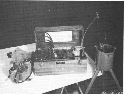
affected. by a number of factors, many directly related to the fabrlcation of the clrcultry and the use of the neasurlng equlpment. Studles have been carrled. out to evaluate the source ancl magnltude of error tntrocluced by some of these factors ancl modiflcattons have been incorporated lnto the design of the lnetallations ln an attempt to eltminate or reduce these erors. Ttrls paper d.escrlbes the fabrtcatlon of a complete thermocoupl-e assembly (Flgure 1) developetl by antl at present used by the Dlvlsion.
Bastcally, the the:rmocouple cable conslsts of copper-constantan duplex wlres placed 1n an o11-f111ed. plastlc plpe for protectlon agalnst danage and moisture. llo facilltate-fteld neasurements the cable ls attachecl to a swltchtng arrangement ln a weatherproof switch box. Uslng the lnstrumentation d.escribed. ln the followlng paragraphs it should. be possible to obtaln temperatures accurate to at least tO.5oF and ln nany cases to t0.3oF lf care ls taken ln the fabrlcatton of the lnstallatlon and. the use of the
readlng instruments. Iwo types of reading lnstruments, a portable preclsion potentloneter ancl an electronlc tempera-ture lnilicator, and instnrctlons for thelr use ln the fteld, h a v e a l r e a d y been described. (1, 2).
THEHMOCOUPT,E @IRCIIII
Ilhen trvo lengths of dlfferent netals are Jolned at both ends and the jr:nctlons subJeoted to different tempera-tures, a small electromotlve foice ls set up ln the oticutt causlng a current to flow. llhese Junctlons are brown as
thermocouples. Ihe electromotlve foroe generated ts a firnotlon of the tenperat[res and the properties of the netals.
Tenperatures are obtalned by ueasurlng the d,ifferenoe ln eleotronottve force betriveen a Junctlon of lcrown tenperatllre,
2
1.€. a referenoe Jrrnctlon, and one of unhlown tenperature. rn the usuar- the:rmooo-uple' olroult, when tempJratrriei' are neasured wlth a portable potentloneter, the-refeienae
Junctlon ls lnmersed ln a- bath of watei ana iGely cnrshed 1ee
temperature of 5zoF. If an rr ls used., the tempenature lh ls lnoorporated into the rted. for automatloalJ-y. A re:mocouple clroult fron the
the readtng. lnstrlnent ls rf eTtrernery lgrg reacr.s are necessary for an lnstaltatlon, lt may_be creilrabre to uJ"-"-ilioie-i6"io ctroult as shown 1n Ft8ure 5. Thls olioult has-Wo ad.vantages:
1. 1t cuts down.the reslstance of the olroult so that
more sensltlve detemlnatlons can be msde -w1th a
potentlometer;
2- lt ls more econonloaL stnce oonstantan wlre r.s qulte expenslve.
One lmportanl^d*?9":l!.g9 of the lgrs.lead ctroult ls that,
because lt has only one donnon constaitan oonduotor fron the Junctlon box to the swltch box, tiie eniire oable wlLl be out of oomnlsslon shourd. thls one wlre be cut or aamaged.
rt ls lnportant that all 6rorrnd tenpe:nature
lnstallatlons be aclequatery proteotdd fion th6 errects of
nolsture and weather-to prbvent corroslon and. po"eibie nshort
ctrcults.rr care must be^taken rn-ile-use of swltches and.
tions, par*loularly wtth
ag the:ma1 gradler.ts at
ble error oan be lntrod.uoecl. rellable temperature measurtng rrkmanshlp and good naterlalg] Ih.ermocouple lllre
rufactured to hlgh standard.s lse oonstantan wlre ts less
gonstantan wlre of proper callbr helnlum 6rad.e or ttsiecial aocure a sUghtly greater cost.
- ,
For most grounil temperature installatlons, ZO-ga duplex wlre is recomnendecl. fhis wlre has 1mo coniluotors, one copper ancl one constantan, 1ndlvtclually encased 1n pol;rvlnyl ohlortde wlth an over-all coverlng of po15m.1ny1 chlorlcte. (Wires having varlous types and conbLr:atlons of ooating materlals are also avallable. ) Although po1yalnyl- . oovered. wlre ls sultable for the gfound temperature cab1e, lt has not been satlsfactory when used for lead wlres because the poLyvlnyL coating tends to crack and. peel when pubJected to flexlng at below freezlng alr temperatures. lead wlre,s havlng an outer Jacket of asbestos and an lnner jacket of teflon are used under these eondttlons. llhese coatlngs do not break 1n oold weather'and are highly reslstant to a-o-raslon ancl rough use whlch they uey recelve lf clraggecl from one
Iocatlon to another or 1f colIed, ancl uncoi].ed.
lhe gensttlvlty of a portable potentloneter ls
greatly affected" if the external reslstance of the ttreriuooouple clrcult ls greater than about 5O ohns. Thls factor becomes extremely lmportant if the temperatures to be measured are close to the reference junctlon temperature of 32oT. ftre slze of the w1re, therefore, Llmlts the length of wlre that can be used.. Normally, for lnstallatlons havlng a length of 75 ft or less, 2O-g wire ls satisfactory. Tor those greater than 75 ft, but not 'longer than 200 ft, 16-ga wlre ls useal. When an electronic temperature indtcator is used, however, much greater lengths of 20-ga wtre can be used. because the sensltlvity of thls lnst:rrment 1s not affeotecl by the
reslstance of wlre lengths normally used in grouncl tempera-ture work.
Mu1tt-conductor cables of varlous wlre Eauges are now avallable and are most convenlent for fabrlcatlng
thermocouple cables. Swttches and Corurectors
llo avolcl the tedlous task of oonnecting lnclivttlual}y many thermocouple Ieads to an lnstrunent when readlngs are cleslred., a rotary seleotor switch ls normally used. 'When a swltch ls lnserted lnto a thermocouple clrcuit a Junctlon wtlI be created at each swltch point. If the swltch ls Bad.e
of unlform materlal and the temperature of each swltch polnt ls the same, this effect w111 cancel- out. For accurate
read,lngs, therefore, ad.equate precautlons must be taken to lnsulate or protect the swltches agalnst the:mal gradlents. In additlon, only copper lead.s should. be attachect to the swltch polnts as copper is llkely to have propertles slnilar to those of the material used. for the swttch polnts.
- 4
leed.s and. Norbhrup rotary seleetor swttches (type 1L-3) are used. by the DlvlsLon. flrese can be obtained'lir-varlous comblnatlons of one to slx poles wlth twelve polnts per pole. They are totarry encrosed., thus assurlng oiean contaet surtaoes. The statlonary corltacts are madE of soLl<l sllver and the brushes are of duiabre strver arloy.
Fartlcular attentlon must be gLven to aIl corurecttons to red,uce or elimlnate alr posslbre effSots oaused,-by trreiuat grad.lents that may exlst at these polnts. For exampi",
constantan-to-constantan conneetlons should not be iof.ierea or Jolned by connectors made of a d.lfferent metal, such as
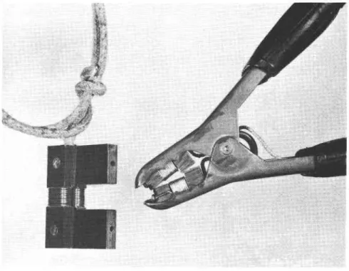
rsurlng Junctlon ls set up at r c e , has stmllar propertles , only connectors made of :ade as the wlre ) should be rply twtsting the constantan slmpre clamp-type connectors and te:mlnal blooks have been developed to ensure a posltlve connssf,lon of copper and constantan wlres for use 1n taklng connectrons bett"""n the swltch box and the readlng lnstrutents rn itre ri"ia.
These conslst of small bakerlde blocks whlch are attacnea to t!" Jaws of the clarnp upon whlch oopper and constantan
wlres are wound indlvlauatly (pleure-4). These wires are
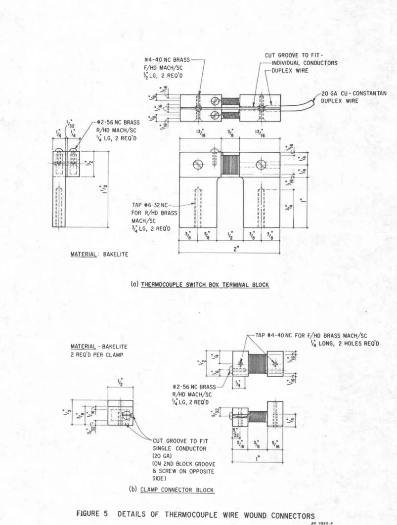
mated. with wlres wound. on similai broci<s fastened ioeether (wlth the wlres lnsulated from one anothu;j-;;;-ilorriEJa r" the swltch box. _ rhe_ grampq used are batteiy uoostei-eaure ollps whlch can be obtalned at hard.ware or Lrectrlcal stores. Details of the const:mctlon of the bakellte blocks are glven th Flgure 5.
CABIE FABRTCATION Drplex lVlre
lhe. thernocou-ple- cable refers to that portlon of the lnstalratton from the lowffi thermoeoupre iuiction rn the. ground_ to the switch box. The number br driprex wir"u
ln the cable wl1r d.epend on the number or porn{;-il th" ground at whlch the temperature 1s deslreit - one auprei *ir"-'ror
each polnt. F"h duplex wlre ln the oable 13 cut to a 1en6th gqu?] to the illstance from the grounil surface to the polnt-tII tl9 grounil where the temperafure ls fo be measuieit.-prii; the dlstance from the ground. surface to the swttch box.
|lhis last shourct be a mlntmum of 5 ft to allow sone flexlblllty ln positloning the swltch box at tfre siie.
- 5
To make a therrnocouple Jr:nctton, take one end of the wlre and. s.trlp back the outer-lnsuration for about I in. strlp about 3/4 1n: of the covering from each of the copper and. constantan conductors. Thoroughly clean each wlre wlth emery cloth or scrape wlth a.krlfe-and trrytst the end.s tightry together for about 3/B tn. cuttlng off any ja6ged ends of w1re. vflth a hot solderlng iron ilsweatrr iedalfrn, resln core solder betureen the twtsis of the therurocouple ltp.- Tg compl-ete the junction, dlp the tlp ln electiicaf lnsurattng- enamel. Two or_thr6e dlpplngs ire requlred., all-owlng the enanel to harden furry-artdr eaah arpping. r ls cut, lt should be
metal tag attached, to each rx wlres have been out and rred., all the wlres are Itrlclants, or slmllar tape
are spaced. at the lnterrrals bhe ground at whlch tempera-rhe complete wire assembly ls then lnserted, 1n a l"rrgtq of frexlble poryethylene hos6 (canadlan Goverrrment Speclflcatlons Board, Spec. No. 4I-GP-5A) wfrfch fs iree of any cuts or breaks. The hose is cut so that it ls about 1 ft ehorter than the 1ongest wlre ln the, cable .
Two methods have been usecl to pLace the cable 1n r of the lnstallatton. An r tnserbed ln the hose from
hose wlth compressed air. A hea wlre can then be-pulled through, !!"_rlg altl pulled. back to the-ui
llgtr! o11 poured lnto the hose wrrr rubrlcate the walls and facilitate pulling the cable through the hose.
ne hose requlred. will depend , the cabIe. Hose wlth an
Id about s1x 16-ea or tweLve nslde dlameter hdse wi1l
V_29:Ba d.uplex wlres, depend.ing ulatlon.covering the wire.
- 6
The duplex wires are posltloned. in the hose so that the lowest thermocouple point is about J in. above the lower end. Each of the duplex wlres in the cable will extencL about 15 ln. above the top of the hose. A lucite or brass plug
(Fleure 6) is then d.riven lnto the hose and securely held ln place by hose clanps, thus sealing the lower end of the hose. lhe lowest thermocouple polnt can be fastened to the plug with cord. so that the thermocouple junctions will not be d.lsplaced when the assembly is co11ed. for shlpment. Ihe O-ft depth (grorrnd. surface) should be well marked. on the outslde of the hose so that the installatlon can be properly positioned in the grouniL.
Mu1ti-conductor CabLe
Multi-cond.uctor thernocouple cables whlch contatn fron 6 to 56 pairs of thermocouple wlre are now avatlable 1 n both 15- and.2O-6a wlre sizes (others on special order). These cables vary 1n outsld.e cliameter, d.ependlng on the number of wires, from about 0,5 in. for a 6-palr cable to a b o u t 1 . 2 1n. for a 56-pair cable of 2O-ga wire. A l4-palr cable of 2O-ga wire with pol;rulnyl chlorlde insulatton on tnd.tvidual wlres, alumlnum-backed. MIIAR tape wrapped. around the bundle of cond.uctors, and an over-alI covering of pol.;nrlnyl chlorlde has an external clianreter of about 0.65 in. Ihls
cable will flt inslde a 5/4-tn. I.D. polyethylene hose. llfre multi-cond.uctor cable is usually placed. in a hose to protect it against damage during shipment anil against uolsture when lnstalled ln the ground.
To fabricate the thermocouple Jrrnctlon the'outer coverlng on the nultl-conductor cable ls cut anit strlppetl back for a distance of 2 in. at.each polnt along the cabLe corresponding to the depth at whlch tenperatures are to be neasured.. The pair of wires (copper and constantan) ln the cab1e, whlch are numbered, colour-cotled and concentrlcally wound. next to each other are selected,, cut anil thetr coverlng
stripped baok for about 1/4 in. Care must be taken to avold-cutting or damaglng any of the other wires in the cable. The ther:mocouple polnt is then matle, following the directlons
given previously. fhe Junctton ls pushed back lnto the bundle of cond.uctors and a coatlng of glyptol applied over the break ln the cable. The joint ts then tlghtly taped. over the break ln the cable.
"llflren fabrication of a1l thernocouple polnts 1n the multl-concluctor cable has been cornpleted., the cable ls then lnsertecl lnto the protectlve polyethylene hose ancl the lower end. of the hose plugged as pr6vlbusly clescribed..
- 7 trong lead fnstallattog
lult, the thermocouples are revi^ously but the lengths of
cable) requlred for 6ach measured, from the Junctlon uhere the temperature ls to :e usuelly placed ln the cable
constantan wtre be used for the
clown the reslstance of the circuit. rhe copper and constantan lead wi.res nrn from the junctton uox io the-^switcrr box.
Detalrs of the constrnrction of the Jrrn"tron box are shown ln 3lgure f.
Prlor-to mallng the sprlce, the ctuprex and. lead. wlres ar_e placed lnslde iurtabl6 tenfutrs or i,oiyeiiiyr"o" hose. Ttle read.wlres are putred ttrrdueh the' jil;ti-il box and the spllce ts mad.e at trre rower end or th; Jun;iioo box.
lro sprloe the copper wlres -together at the Junotlon !o*' -"!rrp back the coverli! from
".ctt-fii"u-io"-ri"in]
carefull;' clean each wlre wftrr emery cloth. tr'or 6ach sprlce over one of the wlregl long Iloe. Next, eross the wlros on anil wlnd one wlre arorrnd Rgr then 5 tlmes at short
the twtsted, Junotion and coat tublng over the sp1lce and.
all coppers have been Jolned., For the eonstantan_ Junctlon, bare 1{ ln. of eaoh of the _*!p_rex oonstantans and.-about J'Ln. or f,he common lead wlre- wlth the d.uplex wlres closely grouped, tlghtly-btncl !F"r together by windlng the comnon constintan aiorurh then. Then tape the spLlce well.
when tlre sprices are completed., they are posltloned lnslde-the Junction box. rhe rowei fltting ti ttren'tlshir-t sorewecl^1+!g place anil the polyethyrene hode securely fastened
l: ll_"_^Ii!t11ql at each end-wrtl ciamps. rhe conprJte assembJ-y
1s gLven a coating of waterprooflng cornpound.. wh6n instalred -ln_the,flelde the-Jrurctlon box musf be iuried et rJas{ I itPgrg1,!l:.ground surface so that a constant temperature wlrr be nalntalned whtle readlngs are betng taken.
- B SYTITCH BOX FABRICATION
Most ground temperature lnstalratlons are located. so that the swltchlng arrangement ls subJected to extremes of wlnter and sunner condltlons" a swltoh 6ox was speotalty deslgned to protect the swltches and wtre conneotions fr6n the effects of weather, tn partlcular from eorroslon and molsture. The retatlvery rarge mass of metal surrorrndlng the swltch termlnars w111 arso help to damp out temperatire differences that can tntrod.uce err6rs at tire temlnirs.
Detalls of the switch box assembry are sho'wn tn Flgures g a n d 9. rt conststs of a rength oi 6-1n. steer pl# sealed on the botton (except for the entry por:t for th6 frlres) and supported. on thrge plpe 1egs. A removabre cover permlis access to the swltches morrnted lnslde. A11 exteriral parts of the swltch box are 61ven at least two coats of an iutomobtle type flnlsh palnt to prevent rustlng.
Dependlng on the number of the:mocouple polnts, one or two rotary selector swltches can be housed ln thls swltch box. rf onry one rotary swltch (12 polnts - slngle pole) ts requlred, lt 1s nount6a at the centre of the silttcrr prate. rf trvo slngre pole swltches or one doubre pole swltch are neoessary, then a lever action toggle switch ls requlred to change from. one_ rota-ry swltch to the other or to change fron_ one p919 to the other on the stngle rotary swltch hivlng 2 poles. Detalls for mounttng two rolary slngie pole swttchds ?Itd a toggle swltch are shorur 1n Flgure io. trre termlnals
that connect the lead wlre from the-readlng lnst:rrment to the thermocouple Junctlon (swltch) wlres are also mounted. 1n the swltch box. lthe swltch mounting prate has a diameter sughtly Smaller than the lnside dlametei of ttre switch box ancl ls-nattb of L/4-Ln. thlck bakeIlte. rt is secured. to the inner rugJ on the swltch box by three screws.
CO$IPIETING THE INSTAII,ATION
. To joln the them_ocouple cable to the swltch box, the wlres extend.ing above the top of the hose nust be
caref_ull-y fed up through the openlng in the base of the switch box. The hose ls then d.ravm-up over the flttlng
that protmdes below the base of the swltch box. rt td tnen secured, to thls f1tt1n6 by means of two hose clamps and. the connection ls coated. lvlth a waterprooflng comporrnd.. llhe wires should be_d,rawn up through the flt{lng wrtn care so that thelr insulatlon is not cut or damaged.i rhe rotary switches and. toggle switch (lf requlred)-are mountecl on the b a k e l l t e p l a t e .
- 9
rhe outer coverlng on each d.uprex wlre is then carefully peeled off for about 4 in. maltng suie ih" -"orr"rlng on the ind.ivld.ual urires 1s not d,amaged.. T[e insulatlon on each conductor is then strlpped bac[ for about r ln. Both copper and constantan wires -shourd be werl cleaned. wlth
are then sold.ered. (lead-tln ;s in ord.er, according to thelr
1.e. the duplex wlre from the :ound surface or the closest ttached. to swltch polnt 1, the next deepest thermocouple ls attaehed. to swltch boint 2, etc. 4ny sgquence g?y be.used but lt is of utmosi rmpbriance that the ident_ity (dgpth) of the thermocoupre polnt 6onnected to
a partlcular swftch polnt be carefull! noted. Arl constantan
wlres are tightly uunatea together reiay to be attaohed. to
the common lead to the swltc[ box terratnar brock.
- A 36-Ln. length of copper-constantan duprex wlre ls
used as the connectlng-Iead froh- the termtndl broik to the
swltch. About 24 in. -of each of the eopper and-consiantan
c,onductors, from whtch the insulation nii been strlpped and
trre wires werl creaned. with emery paper, are wouna 6n trre
terminal block. At the other gndr-4-ln: of the outer coverlng
:rg carefully peeled baclc anil r in. of the copper wtre and
z r-n. or the constantan wlre bared. and. creaned. The copper
read. ls soldered to the tersrinal lug on the switch body.- -rhe constantan lead 1s tnserted m ine bundle of oonstintans
fron.the groun*.thermocoupre- Ju4cttons and the 1 1n. or longer
portlon protrud.tng from the b'inale is then tishtly wrapped " -around the bundle; no sold.er should be used af trris coiirectton. rhe enttre constantan connectlon 1s then dlpped ln glyptol,
carefully coveres ryltt rtspaghettift (prastic' furi"el-;;a wi6ppect wl-th tape so that the bare donductori wlll not coile fn contiot
wtth any of the copper wtres or the switch box houstng. To
ensure that e?cl th-ermocoupLe clrcult ls functtonlng incl has
been connected to the correct swttch point, the resistance of
each clrcult should always be checked. wlth an ohm-meter. so
long as the measurtng_ ;unctlons iq the ground. are 2 ft aparb,
or greater, they can be read.lly ldentifled by thls methoi.
rhe swttch_plate is then carefully plaeect 1n the
swltch box to avoiil d.amage to the w1r6s and.- s6cured. to the
brackets on the inslile watt. The cover plate iJ trren placed
on the swltch box and secured. by means oi the brass thimb screws whlch tlghten the cover against a rubber gasket ln the rlm of the box - thus sealing the installation.
The cable and srvitch box are f1Ired wlth a hlgh
quallty transfomer o11 (e.g. Voltesso No. 3il using a vacuun
- 1 0
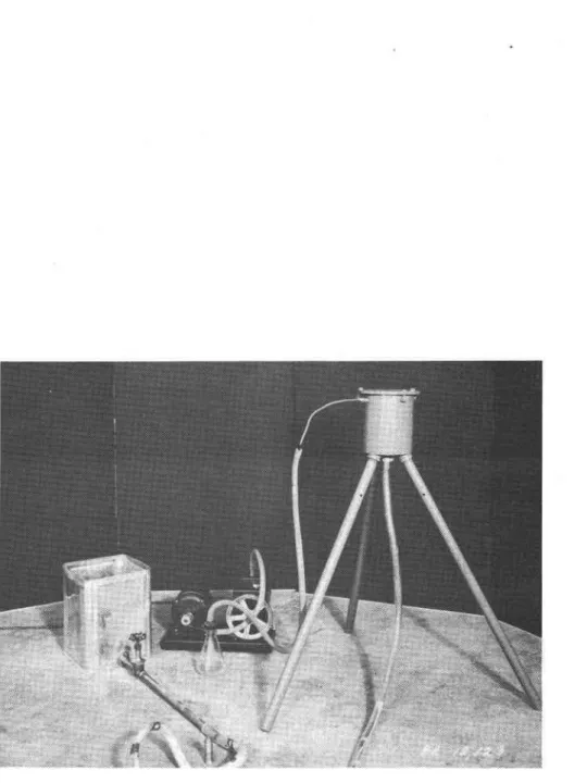
Details of the arrangenent for fllling the
lnstallation urith olL are shorvn ln Figure 11. Frre vacuum pump is connected. to a speclar flttin[ ln the warr of the switch box. The oil provldes addltional protection to the switch points anil terminals in the switch-box ancl wlll a]_so reduce convection currents within the cabre. rf the cable and. the swltch box are to be shlpped separately, the cabre can be fllled with o11 by connectln6 the pump L6 trre top of the hose. The top end of the hose Is plu!;gei slnllar to the bottom end to prevent leakage d.uring siripment. rn thls ease, the hose should be cut so tfiat tt i; atout 6 1n. ronger than the_ rongest wire in the cabre. !'fhen the switch box ind. the cabre are connected. in the fleld, the switch box shouLd. be ftlIed. wlth oi1 to at least the iop of the switch plate. FIEID INSTAII,ATION OF CABIE
r h e complete assembly, i.e., thermocoupre cable and swltch box can be shipped as a unit to trre flerd.l rn nost cases-, however, lt wi-ll be found. convenient to shlp the cable and the swltch box as lndlvidual components to be iorureoted after the cable has been lnstallea i_n tne ground.
At the slte the cable should. be stretcheil out for lts fulr length and straightened. to remove all klnks caused by coiling fdr-shlppinE.-"fr lnstalled. in below_fi6ezhe
temperatures, it should be uncoiled and strai6htened ln-a warm environment and carrled or clragged to thd s1te.
short _cables (r5 ft or less) are normalry lnstalled {n !es! plts or borehores by. simply pushing the c66re- to the d.epth desired. (ln a boreholb) or-uy irxrng it in praee 1n a groove about 1 ft._d*"p in the wal-l- of the p1t. Tie groove and test-plt are then carefurl-y backfilledl with the-orlglnal excavated materlal, to about the original 6enslty. The borehole is backfilled wlth materiar simllar io that remoired. duri.:rg
drilling. tr'or ]opeeq cables, whtch are usualry lnstarled. tn b o r e h o r e s , a weight (ro to 20 rb) must generariy be tled to the bottona end of the cable to keep 1t Stralghi"whlre-it 1s lowered. lnto the' hore. care should be taken in bacldlrllng the hore to ensure tlatr os far as posslbre, the cable ls encased. by soil so that air cursents w1lI n6t clrcutite down the ^hole alongsid.e the cable from the ground. surface, ancl that surface water wilr not f1lr the hole aiound. the cabr6.
TAI{ING READINGS
The lnstallatlon d.escribed. has been d.esigned. to ninimlze the tlme required to connect the measurin[ tnstrument
- 1 r
whgn.taklng readlngs in the fierd, whlle ensurlng that positive and. trouble-free connections will be obtained.. ilhls ha3 been found to be partlcularly irnportant under wlnter oondltlons when the measurlng tnstrument must be transported. and. oonnec-tlons maile at an exposed. field locatlon.
The plate cover of the swltch box nust be removed. The crarnp connector and. lts lead. whlch has been transported. with the measurlng lnstrument, arready conneoted to tt, can then be qulckly crarnped. to lts mating temlnar block oi the swltch mountlng prate 1n the swltch box. lftre cramp must be placed in sueh a way as to corrrect copper to copper and constantan to constantan.' fhls problem can be ellmlnated tf the terminal block ls so shaped. when lt ts made that only one -clamp positlon is posslbre. when the necessary readlngs have been obtalned., the connector clamp 1s removed and the cover of the swttch box replaced.
REFERM{CES
1. Johnston, G. H. lhe measurement of ground temperatures usln6 a modlfted portable potentlometer. Natlonal Research Councll, Dlvlslon of Bullding Research, Tecturtcal Note No. 329t Maroh 1951.
2. Johnston, G. H. The measurement of ground. temperatures uslng a moitifted electronlc temperature lncllcator. National Research Councll, Divislon of Builcling Research, Iechnlcal Note No. 5rO, March 1951.
Figure 1 Ground tenper:ature
S I N G L E P O L E ROTARY SWITCH
swtrcH
Box
WIRE WOUND CONNECTION U S E D ) WIRE WOUND TERMINAL BLOCK r -ELECTRONIC TEMPERATURE INDICATOR PORTABLE PRECISION POTENTIOMETER CONSTANTAN (NO SOLDER M E A S U R I N G T H E R M O C O U P L E _ CoPPER CONSTANTANF I G U R E
2
CIRCUIT FOR GROUND
TEMPERATURE
CORK
THERMOSF L A S K
R E F E R E N C E J U N C T I O N . 2 4 . ' LENGTH
OF LIGHTLY INSULATED, WATERPROOFED
20 GA COPPER AND CONSTANTAN WIRES
C O I T E D O R F O L D E D I N 6.. DEEP I C E B A T H
T H E R M O C O U P L E
I N S T A L L A T I O N
. , 4 . 2 9 5 2 - I -_::-- - | ----i::-:ggr- -- -i - - - - : : l n \liil
TO READING INSTRUMENT 2 0 GA COPPER L E A D W I R E COPPER SPLICE J U N C T I O N B O X M E A S U R I N G T H E R M O C O U P L E ( 2 0 G A DUPLEX W I R E } F - S I N G L E 1 6 GA C O N S T A N T A N (0R 14 GAI LEAD WIREWIRE WOUND CONSTANTAN CONNECTION (NO SOLDER)
F I G U R E
3
L O N G
L E A D T H E R M O C O U P L E
C I R C U I T
Figure 4 Wlre-wound clanp connector and. swltch box terminal block
+ 4 - 4 0 N C B R A S S F/HD MACH/SC
rrj r-c, z neo'o
TAP +6-32 NC
CUT GROOVE TO
FIT-INDIVIDUAL CONOUCTORS DUPLEX WIRE 20 GA CU. CONSTANTAN DUPLEX WIRE +2.56 NC BRASS a4to urcn/sc tro le, z nto'o
M A T E R I A L : B A K E L I T E
FOR R,/HD BRASS
uacH/sc lro tC, e ntQ'O
(ol rxFnuocoupur swrrcH aox rEnutttlt- glocx
S2-56 NC BRASS R^ro MAcH^c rrj tG, a REQ'D
TAP 14-40Nc roa r/uo anass uacx/sc
r{ r-oHe, 2 HoLEs REQ'D
CONNECTORS t a 2 9 r " - 5 MATERIAL - BAKELITE 2 R E O ' D P E R C L A M P GROOVE TO FIT SINGLE CONDUCTOR (20 GA)
(ON zND BLOCK GROOVE 8 SCREW ON OPPOSITE S I D E )
(b) claup coNNEcToR BLocK
sru
:--.$-ti I rli-..-ii|i
iitil
l l i l .!tB+;
J,' i J,' ,8 1 2 n{o) ron % Lo Hose
ron 'rr r,D.
HosE
M A T E R I A L :(b)
8RAS5 OE LIICITEF I G U R E
6
P L U G
F O R
T H E R M O C O U P L E
CABL
E
t R . 2 9 5 2 - 43 t o t . o . ( N o M I N A L ) P I P Et t t z ' 6
T H I S I S T O B E S I L V E R S O L D E R E D B E F O R E T H E R M O C O U P L E S H A V E B E E N PLACED IN JUNCTIOI.I BOX
srD rtt[ o PIPE cAP 2 R E O D S T A N O A R O N I P P L E P L A S T T C P | P E , C G S B S P E C . 4 t - G P - 5 A NOTE P R E S S F I T I T E M I N T O P I P E C A P M A C H I N E F R O M S O L I D B R A S S R O O 2 R E O D t4-u,-@: B R A S S U N L E S S O T H E R W I S E S P E C I F I E D
USE SILVER SOLDER THROUGHOUT. STAINLESS C L A M P , 4 S T E E L H O S E R E O . D
o
F I G U R E 7o 2tN6 ' 909 t7 fp4 PCt /S/.1 ar'tte P.aou.r! c a T a L a a u E , P A 4 1 &
ASSEMELY
ALL E rEB/oz suzf^zEs lo e .tEtuzo al Rusf a fozE4t ilt7Fe z 6tlzH €,/4E4-/- A Dt{Eo 0k EPaxr eEstN .oanila o4 2 oMz co^r oF /4oN dloE PPIuER-(6'A sfe L4p-el
. oNE .o f of A!/oMor/vE frPE EXTEAOB EuailaL
FIGURE 8
( 2 ) uzrt , 6"d uELDED srEEL plpE srAvlpApp 4E\6HT (O.D 6.62t" /.p 6.o6t") I EEQP
4t c,Ezz .za24o 7u4 Ftfftil. 1 42 fUtE rA 6 Prd fxo_
U
MATL: MILD STET,L PLATE / ELQO6c4La: ,Z FM sz
tale : FutL slzt
(l ,orr, lil srauonBo srEEL ptpE v s eEeP
A
\|/@" ,,orr: coLD EILLED srEEL / ELQ?
(fib ,o7r, coLD eoLLEp '7EEL
\-'l
/ pEe'D
ffi
ll "; llSz)
FIGURE 9
LEEDS B ROTARY SWITCH, N O R T H R U P S E L E C T O R T Y P E 3 I - 3 COPPER - CONSTANTAN
WIRE r,V0UND BAKELITE
TERMINAL BLOCK INDEX PLATE SWITCH CRAFT LOCKING, LEVER ACTtoN SW|TCH, TYPE 3037 L
ti
T-M A T E R I A L : B A K E L I T EF I G U R E
I O
S W I T C H
M O U N T I N G
P L A T E F O R T H E R M O C O U P L E
S W I T C H
B O X
_ t R . 2 9 t 2 . t \ - - - /tt
l,
,/
l r r r i i ; i I r I l t l lFigure 11 Equipment set-up for fiIIlng lnstallation with oil