Design of Mechanism and Preliminary Field Validation of
Low-Cost Transfemoral Rotator for Use in the Developing World
The MIT Faculty has made this article openly available.
Please share
how this access benefits you. Your story matters.
Citation
Cavuto, Matthew L., Matthew Chun, Nora Kelsall, Karl Baranov,
Keriann Durgin, Michelle Zhou, V. N. Murthy Arelekatti, and Amos
G. Winter. “Design of Mechanism and Preliminary Field Validation
of Low-Cost Transfemoral Rotator for Use in the Developing World.”
Volume 5A: 40th Mechanisms and Robotics Conference (August 21,
2016).
As Published
http://dx.doi.org/10.1115/DETC2016-59913
Publisher
ASME International
Version
Final published version
Citable link
http://hdl.handle.net/1721.1/120771
Terms of Use
Article is made available in accordance with the publisher's
policy and may be subject to US copyright law. Please refer to the
publisher's site for terms of use.
DESIGN OF MECHANISM AND PRELIMINARY FIELD VALIDATION OF LOW-COST
TRANSFEMORAL ROTATOR FOR USE IN THE DEVELOPING WORLD
Matthew L. Cavuto
Department of Mechanical Engineering Massachusetts Institute of Technology
Cambridge, Massachusetts 02139 Email: mcav@mit.edu
Matthew Chun
Department of Mechanical Engineering Massachusetts Institute of Technology
Cambridge, Massachusetts 02139 Email: mattchun@mit.edu
ABSTRACT
Transfemoral (above-knee) amputees face a unique and challenging set of restrictions to movement and function. Most notably, they are unable to medially rotate their lower-leg and subsequently cross their legs. The best and most common solution to this issue today is a transfemoral rotator, which allows medial rotation of the leg distal to the knee through a lockable turntable mechanism. However, currently available transfemoral rotators can cost thousands of dollars, and few equivalent technologies exist in the developing world. This paper, supported by the results of field studies and user testing, establishes a framework for the design of a low-cost and easily manufacturable transfemoral rotator for use in the developing world. Two prototypes are presented, each with a unique internal locking mechanism and form. A preliminary field study was conducted on six transfemoral amputees in India and qualitative user and prosthetist feedback was collected. Both prototypes
successfully allowed all subjects to complete tasks such as crossing legs, putting on pants, and tying shoes while maintaining functionality of walking and standing. Future iterations of the mechanism will be guided by a combination of the most positively received features of the prototypes and general feedback suggestions from the users.
INTRODUCTION
This work is focused on designing a low-cost and easily manufacturable transfemoral rotator, for application in the developing world, which can achieve medial rotation of the lower-leg and facilitate a return to daily activities and necessities for transfemoral (above-knee) amputees.
The World Health Organization (WHO) has estimated that there are about 30 million amputees in low-income countries as of 2010 [1]. In addition, it is estimated that there are over 9
Nora Kelsall Department of Mechanical Engineering Massachusetts Institute of Technology Cambridge, Massachusetts 02139 Email: nkelsall@mit.edu Karl Baranov
Department of Mechanical Engineering Massachusetts Institute of Technology
Cambridge, Massachusetts 02139 Email: kbaranov@mit.edu
Keriann Durgin
Department of Chemical Engineering Massachusetts Institute of Technology
Cambridge, Massachusetts 02139 Email: kdurgin@mit.edu
Michelle Zhou
Department of Physical Therapy Boston University Boston, Massachusetts 02215
Email: mzhou95@bu.edu
V. N. Murthy Arelekatti
Global Engineering and Research Lab Department of Mechanical Engineering Massachusetts Institute of Technology
Cambridge, Massachusetts 02139 Email: murthya@mit.edu
Amos G. Winter, V
Global Engineering and Research Lab Department of Mechanical
Engineering
Massachusetts Institute of Technology Cambridge, Massachusetts 02139
Email: awinter@mit.edu
Proceedings of the ASME 2016 International Design Engineering Technical Conferences and Computers and Information in Engineering Conference IDETC/CIE 2016 August 21-24, 2016, Charlotte, North Carolina
million transfemoral amputees in Asia, Africa, and South America, with the majority residing in developing nations [2]. This number has been increasing in recent years due to a variety of causes including poor health standards, traffic regulation, and the increasing use of improvised weapons in conflict regions of the world [3]. It is estimated that only 5-15% of these amputees receive a prosthetic device, and up to 80% of amputees are unable to afford a prosthesis [4].
In addition to limited resources, amputees in the developing world face a very different set of obstacles than their counterparts in developed countries, as defined by the United Nation’s Human Development Index (HDI) [5]. In the United States, insurance companies and a higher HDI allow people to spend tens of thousands of dollars on a customized prosthesis that will be serviced multiple times a year. However, in developing countries, amputees are often living off of less than $1 a day and cannot afford such expensive devices [6]. In India, many amputees go unemployed, unable to perform physically strenuous agricultural or manual labor that comprises 75% of Indians’ livelihood [7]. Additionally, many amputees live in remote areas, far away from their prosthetist or clinician [8]. This suggests that ideal prostheses should be durable, modular, and self-serviceable so the patient can fix or replace a broken piece themselves, without having to travel for days to receive assistance.
However, even after receiving a prosthesis, many amputees, especially transfemoral amputees, face challenges in their everyday life. One of the biggest challenges, and the one addressed in this paper, is the inability to achieve medial rotation of the lower leg. In a previous study of prosthetic design requirements, 87% of surveyed transfemoral amputees stated that crossing legs was not an easy task, and 100% stated that the ability to cross their legs would significantly improve their daily lives [9]. While it can be caused by a variety of reasons, this lack of rotation ability is most commonly due to the typically large and restrictive sockets as well as loss of hip flexor/extensor muscles during the amputation. The social stigmatization of amputees and the psychosocial challenges faced by amputees are well documented [10], and a seamless return to daily economic and social activities is important to the rehabilitation process [11]. Thus, in regions such as India, where cross legged sitting is a daily part of many occupations, social activities, and religious functions, medial rotation of the lower leg is extremely important.
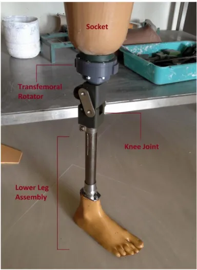
A common solution to this issue is a transfemoral rotator, which is placed between the knee joint and the distal prosthetic leg assembly (Fig. 1). Although a few successful rotators have been designed and exist in the developed world, they can cost thousands of dollars and are often comprised of many complicated parts to manufacture [12].
Unfortunately, this cost and manufacturability barrier is not unique to transfemoral rotators. As noted above, nearly all prosthetic components come with a high cost to users. This is especially true in the case of prosthetic knee joints. While knee joints found commonly in the developed world can and are used in the developing world, their high cost often limits their
application. Thus multiple low-cost knee joints have been designed specifically for this purpose [13]. One of the most widely used of these low-cost knee joints is the four-bar polycentric Stanford-Jaipur Knee (Fig. 1), distributed by the JaipurFoot Organization, also known as Bhagwan Mahaveer Viklang Sahayata Samiti (BMVSS) [2]. Costing under $20 to manufacture, the Stanford-Jaipur Knee has shown much success in low-income areas of India. This low-cost, however, comes with a price, as in lieu of the universal pyramid connection system found on nearly all other knee joints, the Stanford-Jaipur Knee features a proprietary large screw connection system (Fig. 5).
Figure 1. FULLY ASSEMBLED PROSTHESIS, SHOWING
PROPER PLACEMENT OF A TRANSFEMORAL ROTATOR AND THE STANFORD-JAIPUR KNEE FROM THE JAIPURFOOT ORGANIZATION (BMVSS).
In this context, the focus of this work is to design a low-cost, durable, and easily manufacturable transfemoral rotator that can facilitate a return to daily cultural, social, and religious activities for transfemoral amputees in the developing world. Additionally, the transfemoral rotator must meet pertinent socio-economic and culturally-influenced aesthetic needs, and interface with both the universal pyramid connection system of
the developed world and the proprietary large screw connection system of the Stanford-Jaipur Knee (Fig. 5). Thus, based on the above mission statement, this paper is focused on the following: (I) Classification of functional design requirements based on reported data in literature and established standards by current designs. (II) Conceptual design of internal mechanisms and prototype construction, in order to satisfy established functional requirements. (III) Preliminary field validation in India of both prototypes through user trials and qualitative feedback interviews.
FUNCTIONAL REQUIREMENTS
In establishing the functional requirements for the design, a number of cultural, biomechanical/safety, and industrial factors were considered. To do this, the established literature and cultural stigmas in developing world countries were examined, taking into consideration current standards set by successful transfemoral rotators in the developed world. Furthermore, in considering a transition from proof-of-concept prototypes to manufacturable products, industrial requirements were considered that would aid in potentially bringing a product to the market, where it could actually help people.
The cultural functional requirements are established from a combination of the aforementioned social and religious practices and stigmas. The transfemoral rotator must facilitate a return to such practices as cross-legged sitting, while eating or socializing, squatting, and getting in and out of tight spaces, such as a rickshaw. Additionally, due to the stigmas and prejudices surrounding amputees in many countries of the developing world [10, 14], the transfemoral rotator must be easily concealable and operable under pants, and lack any obvious operation noise.
The biomechanical and safety function requirements are established from literature on currently available transfemoral rotators. Namely, the transfemoral rotator must not add noticeable weight or height (in the form of knee joint displacement) to the prosthesis, such that normal gait dynamics are affected. The rotator must also feature a substantial weight rating, in order to accommodate a wide range of patients. All target values (Table 1) were chosen based on standards set by current developed world rotators, such as the Knee Rotational Adapter from Ossur Hf [12]. Lastly, it is important to preserve the stability of the prosthesis in a locked position while walking, and thus the rotator must repeatedly align to a correct walking position and have little to no rotation during the gait cycle.
The industrial and practical functional requirements are established in order to facilitate a transition from a prototype into a robust, diverse, and low-cost final product. As previously mentioned, the transfemoral rotator must interface with both the proprietary screw connection system of the Stanford-Jaipur Knee and the more universal pyramid connection system of most other prostheses sold around the world. Keeping robustness and longevity in mind, the transfemoral rotator must also feature an entirely internal mechanism, sealed from dust, dirt, and water, and be easily serviceable when wear is present. Lastly, in order to reach desired users in the developing world, the cost per
device is targeted to be under $20—the cost of the Stanford-Jaipur knee [2]. An extensive list of functional requirements was subsequently constructed, and used to guide all prototype design and evaluation (Table 1).
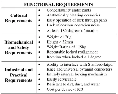
Table 1. FUNCTIONAL REQUIREMENTS ESTABLISHED BASED ON CULTURAL, BIOMECHANICAL AND SAFETY, AND IDUSTRIAL AND PRACTICAL CONSIDERATIONS.
FUNCTIONAL REQUIREMENTS Cultural
Requirements
Concealability under pants Aesthetically pleasing cosmetics Easy operation of lock through pants Lack of obvious operation noise
At least 180 degrees of rotation
Biomechanical and Safety Requirements Weight < 176g Height < 32mm Weight Rating of 115kg Repeatable locked realignment Rotation when locked < 1 degree
Industrial and Practical Requirements
Ability to interface with Stanford-Jaipur Knee and universal pyramid connectors Entirely internal locking mechanism Easily serviceable
Resistant to dirt, dust, and water Cost per device < $20
DESIGN
As mentioned in the previous section and tabulated above, the prototypes described in this paper were designed according to a chosen set of cultural, biomechanical, safety, industrial, and practical requirements. These requirements were chosen through a comprehensive literature review of prior art in the developed world as well as prosthetic solutions in the developing world. One such example of prior art was the Knee Rotational Adapter from Ossur Hf [12]. Composed of many moving parts, springs, and expensive materials such as titanium, such a design is neither easily manufactured nor financially feasible in the developing world. Thus the prototypes described in this paper were designed with less than five moving parts, with the entire assembly easily manufactured through a variety of in-house processes such as milling and 3D printing.
In order to receive feedback on preferred operation, shape, size, and weight, two prototypes were designed for this study. The first transfemoral rotator was designed for single-button operation, while the second transfemoral rotator used a two-button locking mechanism. For the remainder of this work, these prototypes will be referred to as rotator A and rotator B respectively. As with conventional transfemoral rotators, the prototypes were both designed to be placed in between the prosthetic socket and knee joint (Fig. 1). This allows the lower leg, from the knee joint down, to be rotated freely, when the locking mechanisms of the rotators are unlocked. The two main
stages of operations of both rotators, locked walking position and unlocked sitting position are demonstrated in Fig 4.
Both Rotator A and B, were made using Delrin and densely printed ABS (Fig. 5). The dimensions and weight of each prototype are listed in Table 2. It should be noted that despite exceeding the functional requirements of height and weight, it was determined that these preliminary prototypes should be over-engineered for the safety of the study’s subjects, with the intention of focusing on feedback of the mechanism and appearance of each prototype. Future iterations of the design will thus be made smaller and more lightweight, following more extensive strength testing.
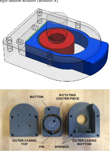
Single-Button Rotator (Rotator A)
Figure 2. SHOWN ABOVE IS A 3D RENDERING OF ROTATOR
A WITH THE INTERNAL PARTS COLORED. SHOWN BELOW IS THE DISSASEMBLED ROTATOR A WITH ALL PARTS LABELED.
Rotator A was designed to be operated by a single button, inspired by the operating mechanisms of most transfemoral rotators in the developed world. The internal mechanism of the rotator can be seen in Figure 2. A spring loaded pin (green) is used to lock into the rotating centerpiece (red), which fastens directly to the user’s prosthetic knee. All are located inside a two part outer casing (transparent). When the button (blue) is
depressed, the pin disengages, allowing for 360 degree rotation of the distal prosthetic leg assembly. Once the user releases the button, and rotates the leg assembly, the pin automatically locks into the anatomical walking position. The large button allows easy location and operation through the user’s pants, and the internal mechanism provides the user the choice whether or not to receive audible feedback, in order to ensure the leg has relocked into walking position.
In order to simplify the internal mechanism and allow for easy manufacturing using a CNC mill, an oblong shape was chosen to create room for the button to be depressed. For user testing, prototypes of this design were made to be compatible with both the Jaipur-Stanford knee provided by JaipurFoot, as well as the more universal pyramid connection system used by Mobility India and many other clinics around the world (Fig. 5).
Two-Button Rotator (Rotator B)
Figure 3. SHOWN ABOVE IS A 3D RENDERING OF ROTATOR
B WITH THE INTERNAL PARTS COLORED. SHOWN BELOW IS THE DISSASEMBLED ROTATOR B WITH ALL PARTS LABELED.
Rotator B was designed to be operated by two buttons, with the internal locking mechanism inspired by push button spring clips. Found in many devices that feature telescoping tubes, ranging from crutches to walkers, push button spring clips are a
cheap, simplistic, and time-tested way to achieve constrained and adjustable rotation between two nested cylinders.
Rotator B is composed of an inner cylinder (red), a split outer casing (transparent), two buttons (blue), and two push button spring clips (green) (Fig. 3). When the buttons are depressed, the push button spring clips are forced through the holes in the casing wall, allowing the inner cylinder to rotate freely. So long as the two buttons remain depressed, the inner cylinder, which is attached to the distal prosthetic leg assembly, is allowed to rotate 360 degrees. If the buttons are released after the initial unlocking, the inner cylinder will lock in place after 180 degrees of rotation as the push button spring clips reengage the holes in the casing wall.
As with Rotator A, two versions of this prototype were made to be compatible with both the Jaipur Stanford knee from BMVSS, as well as with the more universal pyramid connection system used by Mobility India (Fig. 5).
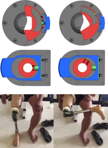
Figure 4. SHOWN ARE THE TWO STAGES OF OPERATION,
LOCKED AND UNLOCKED, FOR BOTH ROTATORS IN A CUTAWAY CAD VIEW (a), AS WELL AS CORROSPONDING PHYSICAL REPRESENTATIONS WITH ROTATOR B IN USE DURING TESTING (b)
Table 2.DESIGN SPECIFICATIONS FOR ROTATOR A AND B
DESIGN SPECIFICATIONS Added Height (cm) Max. Length (cm) Max. Width (cm) Weight (g) Rotator A Delrin 4.54 11.65 8.51 361 ABS 4.03 11.88 8.51 192 Rotator B Delrin/ABS 5.52 9.27 8.63 225 ABS 4.37 9.27 8.47 176
Figure 5. FULLY ASSEMBLED PROTOTYPES A AND B WITH
BOTH THE PROPRIETARY SCREW CONNECTOR FROM THE JAIPURFOOT ORGANIZATION AND THE MORE UNIVERSAL PYRAMID CONNECTORS USED AT MOBILITY INDIA.
USER TESTING PROTOCOL
Both prototypes were tested through a partnership with Mobility India and JaipurFoot. Both organizations, founded and based in India, are non-profit NGOs, who strive to provide prostheses to impoverished amputees at little to no cost. Three days were spent at each facility, each day testing and getting feedback from a single user. The six users consisted of men ranging in age from 20 to 79, and in weight from 42 to 83kg (sans
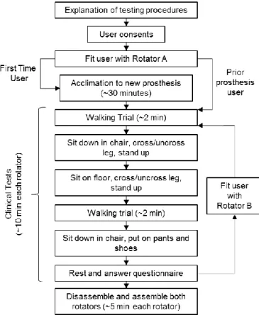
prosthesis). The functionality of the transfemoral prosthesis was assessed with a series of clinical tests. The clinical testing primarily served to analyze the functional aspect of the rotators and included having trials of the patient walking, standing up and sitting down, crossing and uncrossing legs with the rotator, tying and untying shoe laces, and putting on pants. The user testing protocol (Fig. 6) was approved by the MIT Committee on the Use of Humans as Experimental Subjects.
A user-tester questionnaire was used to evaluate patient response to the rotator. Translators at Mobility India and JaipurFoot interviewed each subject in his local language in order to complete the form. The purpose of the questionnaire was to gain internal feedback from the patient.
Figure 6. FLOWCHART OF USER TESTING PROTOCOL The form can be divided into two categories: compliance and functional feedback. In compliance feedback, patients discussed their feelings on the look of the device, use, and how comfortable they feel with having this rotator added to their current prosthesis. Through these questions, it was determined if the patient would want to use the device, taking aesthetics or concealability into consideration. If a patient feels that this device is displeasing to the eye, or not easily concealable under normal pants, then the patient is less likely to use the rotator [11].
The second category, functional feedback, was meant to gain patient feedback on the overall function of the device and
how it helps the function of their prosthesis in everyday life. Although previous testing was done to ensure a secure fit between the threading of the rotator and the Stanford-Jaipur knee, testing was not done under patient weight loading. Therefore, it was important to determine that this fit remained secure under realistic loading and unloading tests. Additionally, it was important to determine if the rotator had any noticeable change in the walking pattern of the patient or if it unlocked while the patient was walking. Either of these changes would result in the patient being far less likely to use the device [11]. All of these questions were used to provide useful feedback on critical functionality of the device and are crucial in guiding further iterations of the trans-femoral rotator.
The protocol at Mobility India consisted of roughly one half-hour block of testing with each prototype for each patient. The questionnaire form was filled out, with the assistance of a translator as needed, at the end of each block to allow the user to rest. After testing both prototypes, the user was asked to compare them and was shown how to assemble and disassemble them completely. This last step was administered in order to gauge whether or not the users thought that they could service and maintain the rotators without the assistance of a prosthetist. A similar protocol was followed at JaipurFoot, with an additional half hour at the beginning for the new users to get used to walking on their prosthesis (Fig. 6). Finally, at the conclusion of testing at each organization, the prosthetists and technicians were asked to provide qualitative feedback on each design.
RESULTS OF USER TESTING
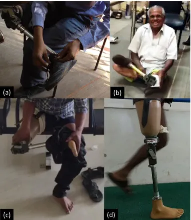
The user testing of both rotators allowed patients to perform a full range of activities including many that they previously could not conduct without the assistance of a rotator. With both rotators, all six subjects were able to cross and uncross their legs while sitting on the ground and on a chair, and were able to put on pants, and tie/untie their shoes (Fig. 7). Moreover, this additional functionality did not preclude any subject’s previously ability to walk, stand up, or sit down. On a scale of 4, patients agreed with the statement that “The addition of a rotator is useful and an improvement in day to day life” with a score of 3.50 ± 0.548 (Table 3).
The user feedback for all six days was very consistent with the most agreed upon points with respect to the different button configurations and shapes of the rotators. With respect to the button configurations, the one button operation of prototype A was preferred to the two button operation of prototype B (Table 3). Users cited multiple reasons for this preference. First, some users found that their hand was too small to reach both buttons comfortably. Second, users found that the two button design was harder and more awkward to locate through pants. Finally, multiple users appreciated being able to subtly operate the single button with their palm in order to achieve a more natural appearance when crossing their legs.
Figure 7. USERS WEARING ROTATORS PERFORMING A
VARIETY OF TASKS INCLUDING (A) TYING SHOES, (B) SITTING CROSS LEGGED, (C) PUTTING ON PANTS, AND (D) WALKING
With respect to the size and shape of the prototypes, users preferred the round and more compact form factor of prototype B over the oblong and bulky form of prototype A (Table 3). The circular design was found to be more aesthetically appealing both with and without pants. Users noted that the round silhouette under pants looked more similar to a real leg. Feedback from the prosthetists added that the round shape would also fit more easily under a foam cosmetic covering, something the majority of their patients use.
Other fairly universal comments included concerns about the height of the rotator. While no user minded the circumferential size of prototype B, most thought that both prototypes were too tall. Concerns over this issue were raised when the users were sitting down and both legs were bent. In this position, the knee joint of the prosthesis with the rotator is displaced significantly farther out than without. This displacement made it too obvious that the user was an amputee. As mentioned before, however, this was not a problem at the JaipurFoot organization thanks to the custom sockets.
Observational feedback and feedback from both Mobility India and JaipurFoot technicians was also positive. They were surprised by and appreciated the simplistic and robust designs of the two prototypes. Both patients and technicians expected much more complicated mechanisms. This is further supported by the fact that after being shown how the mechanisms worked, all subjects were able to disassemble and assemble both
mechanisms independently. Lastly, the JaipurFoot organization (BMVSS) expressed a strong preference for the use of push button spring clips over conventional coil springs, citing their increased durability and longevity.
Table 3. SELECTED USER RESPONSES TO QUESTIONNAIRE. SCORES RANGE FROM 1 TO 4 WITH HIGHER SCORE CORRESPONDING TO STRONGER AGREEMENT WITH STATEMENT (N=6)
SELECTED RESPONSES TO USER QUESTIONNAIRE Question Rotator A
(Mean ± S.D.)
Rotator B
(Mean ± S.D.) The lock of the rotator is
easily engaged and disengaged
3.50 ± 0.548 3.00 ± 0.707
The rotator size and weight is comfortable while
walking
3.17 ± 0.753 3.33 ± 0.516
The addition of a rotator is useful and an improvement
in day to day life
3.50 ± 0.548
DISCUSSION
The strong agreement with the statement that the rotators are a useful improvement to everyday life supports the fact that there is a high demand for low-cost rotator options for Indian transfemoral amputees. After speaking to Mobility India and JaipurFoot, which service many of India’s amputees, providing rotators is currently a very limited sector of their operations, mostly because of prohibitive costs and compatibility issues. Thus, the authors believe that there is a great need for low-cost transfemoral rotator options that are compatible with prosthetic knees and sockets in the developing world and can be readily incorporated into the operations of NGOs. The authors expect that the increased supply of such devices would improve the quality of life of amputees, and increase compliance rates in the developing world. Both organizations have expressed interest in continued collaboration in the development of a low-cost transfemoral rotator.
Furthermore, the results of this study can be used as a guide for future development of transfemoral rotators. The preference of users for a single button rotator over a two button mechanism, and a circular shape over an oblong form is consistent with the designs of rotators in the developed world [12]. While the results of this study are not significant due to a small sample size (n=6) and a limited scoring scale of 1-4, the consistent results are encouraging enough to guide future design iterations. In combination with JaipurFoot’s strong preference for the use of push button spring clips over conventional coil springs, the authors believe a single-button, circular rotator using push button spring clips would be ideally received by Indian amputees and NGOs. Moreover, while size and weight of designs should ideally be minimized, patients had no issue with the diameter or weight of rotator B, suggesting that a weight of 225g and
diameter of 9.27cm are acceptable functional requirements of future rotator designs. As stated previously, more extensive strength testing and material selection in the future will allow for further minimization of these parameters. Future materials that will be explored include nylon used in the original Stanford-Jaipur knee, 3D printed ABS for components under minimal stress, and aluminum for its low cost and relatively high strength-to-weight ratio.
Finally, because of the simplicity of the designs, all six subjects were able to understand the mechanisms and assemble/disassemble the rotators. The authors found that this strongly increased the transparency of the treatment and rehabilitation process, giving users increased confidence in the technology. In addition to having increased personal ownership of their prosthetic device, the ability of subjects to self-service their device is particularly important in developing world applications, where amputees may have to travel many miles to the nearest clinic, and bear the opportunity cost of earning much needed income [8].
Limitations of the Study
The current study was found to have the following limitations that must be taken into account in future transfemoral rotator design and clinical testing:
1) Two subjects at Mobility India who were already prosthesis users were fitted with a rotator connected to a Stanford-Jaipur knee, and were unable to make comparisons while using their normal knee joint. 2) One subject at Mobility India and all three subjects at
JaipurFoot were first time prosthetic users. This gave the subjects limited ability to comment on how the addition of the rotator would improve their standard of living. Thus feedback was focused on the form and function of the rotator, with lifestyle questions in the hypothetical. In addition, first time prosthesis users were given approximately an extra 30 minutes to walk around to get used their new prosthesis before beginning testing.
3) For testing at Mobility India, patients used their current socket, knee joint, and lower leg assembly for testing. This meant that the knee joint was somewhat displaced to a more distal position. At JaipurFoot, brand new sockets and complete prostheses were made after the authors arrived, leaving room for the addition of the rotator without displacement of the knee joint. Nevertheless, judging from the consistency of feedback at the two organizations, this difference had little to no impact on the testing results.
FUTURE WORK
Both the JaipurFoot organization and Mobility India have expressed interest in continuing the collaboration through future design iterations. Next steps will include incorporating user and technician feedback in order to combine the most well received
features of both prototypes into one optimized design. From there, material selection will be refined through stress testing and various manufacturing processes, balancing cost of production and durability. Material and manufacturing sourcing will be sought out local to the two above testing organizations in India.
ACKNOWLEDGMENTS
The authors would like to thank MIT’s Global Engineering and Research (GEAR) Lab and the Biomechatronics Group of the MIT Media Lab for their technical expertise and resources. The authors would also like to acknowledge Bhagwan Mahaveer Viklang Sahayata Samitit (BMVSS, also known as the JaipurFoot organization) and Mobility India, for their partnership in the design and testing of the low-cost transfemoral rotator. Finally, the authors would like to acknowledge Bryan Ranger and Katerina Mantzavinou for instructing MIT’s Prosthetics for the Developing World course, through which this project began. Funding for this research was provided by MIT’s D-Lab and MISTI (MIT International Science and Technology Initiatives).
REFERENCES
[1] J. Pearlman, R. Cooper, M. Krizack, A. Lindsley, Y. Wu, K. Reisinger, W. Armstrong, H. Casanova, H. Chhabra, and J. Noon, “Lower-limb prostheses and wheelchairs in low-income countries: An Overview,” IEEE Eng. Med.
Biol. Mag., vol. 27, no. 2, pp. 12–22, 2008.
[2] S. R. Hamner, V. G. Narayan, and K. M. Donaldson, “Designing for Scale: Development of the ReMotion Knee for Global Emerging Markets,” Ann. Biomed.
Eng., vol. 41, no. 9, pp. 1851–1859, 2013.
[3] E. Strait, G. McGimpsey, and T. Bradford, “Limb Prosthetics Services and Devices,” White Pap., no. January, pp. 1–35, 2006.
[4] D. Cummings, “Prosthetics in the developing world: a review of the literature ,” Prosthet.Orthot.Int. , vol. 20 , no. 0309–3646 (Print), pp. 51–60, 1996.
[5] U. N. D. P. UNDP, “Human Development Report 2015 Work for Human Development,” p. 288, 2015.
[6] S. L. Hart, “Low-income markets present a prodigious opportunity for the world’s wealthiest companies — to seek their fortunes and bring prosperity to the aspiring poor,” no. 48, pp. 1–23, 2008.
[7] International Institute for Population Sciences (IIPS) and Marco International, National Family Health Survey
(NFHS-3), 2005-06: India: Volume I., vol. 18, no. 7.
2007.
[8] D. Mohan, “A report on amputees in India,” Orthot.
prosthetics, vol. 40, no. 1, pp. 16–32, 1986.
[9] Narang, Y.S. Identification of Design Requirements for a High-Performance, Low-Cost, Passive Prosthetic Knee Through User Analysis and Dynamic Simulation.
(Masters Thesis, MIT Department of Mechanical Engineering) June 2013.
[10] O. Horgan and M. MacLachlan, “Psychosocial adjustment to lower-limb amputation: a review.,”
Disabil. Rehabil., vol. 26, no. 14–15, pp. 837–850, 2004.
[11] D. Wyss and W. L. A. J. Cleghorn, “Evaluation and design of a globally applicable rear-locking prosthetic knee mechanism,” vol. MR92958, p. 136, 2012. [12] S. Olafsson, G. Ingimarsson, and D. Landry, “Knee
rotational adapter.” US 20140222166 A1. Google Patents, 07-Aug-2014.
[13] J. Andrysek, “Lower-limb prosthetic technologies in the developing world: A review of literature from 1994– 2010,” Prosthet. Orthot. Int., vol. 34, no. 4, pp. 378–98, 2010.
[14] J. P. Dormans, R. C. Fisher, and S. G. Pill, “Orthopaedics in the developing world: present and future concerns.,”
J. Am. Acad. Orthop. Surg., vol. 9, no. 5, pp. 289–296,