DESIGN APPROACHES TO STRUCTURAL OPTIMIZATION by
Memduh Ali Tayar Diplom Ingenieur Universitaet Stuttgart
Stuttgart, Federal Republic of Germany
1983
SUBMITTED TO THE DEPARTMENT OF ARCHITECTURE IN PARTIAL FULFILLMENT OF THE REQUIREMENTS OF THE
DEGREE
MASTER OF SCIENCE IN ARCHITECTURE STUDIES AT THE
MASSACHUSETTS INSTITUTE OF TECHNOLOGY JUNE, 1986
© Memduh Ali Tayar 1986 The author hereby grants to M.I.T.
permission to reproduce and to distribute publicly copies of this thesis document in whole or in part
Signature of the author
M. Ali Tayar Department of Architecture
May 15,1986 Ceprtified by_________________
Acceped byfu
MASSACHUSEM OF TECHNOLOGYINST;TUTE
800
JUN
0
Waclaw Zalewski Professor of Structures Thesis supervisor Julian Beinart Chairman Departmental Committee for Graduate StudentsDesign Approaches To Structural Optimization
by Memduh All Tayar
Submitted to the Department of Architecture on May 15, 1986 in partial fulfillment of the requirements for the Degree of
Master of Science in Architecture Studies
ABSTRACT
The objective of this thesis is to develop design approaches to structural optimization. In the example of
three-dimensional grid structures, widely known as 'space frames', possible configurations are explored
which maximize the load-bearing capacity of the system in relation to its weight. The study has been organized in two chapters:
The first chapter starts with a brief review of structural concepts. Along with Gothic as a historical example to
optimization, modem analytical methods to optimal structural design are presented which include
Maxwell's Lemma, Michell's Fields and Ultimate Strength Analysis.
In the second part of the thesis the design solutions are presented. The emphasis lies on a deployable space frame which is based on bar-joist like elements.
Thesis Supervisor: Waclaw Zalewski Title: Professor of Structures
to my mother lihan Tayar to my father Omer Tayyar Tayar and to my teacher Hans Jochen Oster
and to Janette and Ron for making my German sound like English, thank you
TABLE OF CONTENTS
0 0.00 Introduction 6
1 1.00 On Structural Behavior 10
1.10 How Structures Resist Loads 11
1.20 On Strai Energy 12
1.30 On Principal Stresses 13
1.40 Minimum Energy Requirement 14
2.00 A Historical Approach To Optimal Structural Design: Gothic 18
3.00 AnOverview 21
3.01 Approaches To Structural Design 22
3.02 Optimal Structural Design 23
3.10 Braced Frameworks 25
3.10 Maxwells Lemma 26
3.12 Michels Suctures 27
3.20 Slabs 33
3.21 An Approach To Optimal Design Of Slab Structures 34
2 1.00 Conclusions And Design Guide-Lines 45
1.10 An Example: Reinforced Concrete 47
1.20 Design Solutions 52
1.21 Design Solutions With Exposed Tensile Network 53
A 1.00 References 82
2.00 References For Figures And Diagrams 83
0.00 INTRODUCTION
The objective of this thesis is the development of design approaches to structural optimization problems.
In the context of this thesis, optimization will be focused on the process of maximizing the ratio of
load-bearing capacity to material consumption. Thus, optimal structures represent solutions of minimum weight for specified loads and materials.
other fields of engineering. Developments of new analytical programming techniques have encouraged a trend towards design optimization especially in the field of mechanical engineering. The application of analytical optimal design solutions to structural engineering and architectural form represents a highly unexplored area. We may expect that the general trend towards the conservative use of resources will eventually impose the application of optimal design techniques also on the building industry. Considering also the energy consumption involved in the manufacturing process of materials the importance of efficient utilization of material properties becomes evident.
The structure of the thesis has been organized in two chapters which again are divided into parts. The first chapter in sequence and content reflects the research I have done into the theoretic background and the
history of optimization in the context of structural design.
The first part in this chapter reviews briefly the fundamental concepts of structural behavior focusing on the link between the energy theorem and the basic principles of statics. In the second part Gothic is presented as a historic approach to empirical optimization of structural design.
The third part focuses on analytical methods in the design of optimal structures. Maxwell's Lemma and Michell's Fields are discussed. Both are restricted to the synthesis of braced frameworks within the elastic range of structural behavior. As an example to ultimate strength analysis concerning slabs, G.I.N. Rozvany's Optimal Design Of Flexural Systems is reviewed.
The second chapter of the thesis is a documentation of design solutions. Various approaches to space-frame-structures are reviewed with the goal of pushing existing solutions towards configurations which utilize material properties of the system in a more efficient way. New concepts are introduced which are based on the reinforcement of the three-dimensional framework with a network of tensile elements in various alternatives. The proposed solutions are presented in two groups:
a) Solutions which have an exposed network of tensile elements.
b) Solutions in which the tensile network is incorporated into the elements of the system.
As a subgroup of the first approach, a deployable structural system based on bar-joist-like elements is presented in detail.
"With a judicious sense of economy, or intelligent laziness, a structure will always choose to channel its loads to the ground by the easiest of the many paths available. This is the path requiring the minimum amount of work on the part of the structural materials and is a consequence of what is termed in physics The law of least work'. Structures behave humanly in this respect too." MarioSalvadori
1.00 ON STRUCTURAL BEHAVIOR
In the design process the development of the structural system represents a major step which in most cases is left in the hands of the structural engineer. Although the majority of architecture programs provide courses on basic concepts of structural behavior, these seldom succeed in giving the students adequate
conceptual understanding of how structural systems work. The mathematical background of these
problems is highly complex and goes well beyond the grasp of many an architect. Here, I would like to mention that the treatment of these problems can be found in the realm of thermodynamics and fracture mechanics.
The most comprehensive explanation of structural concepts, "stripped of its mathematics", as stated by
J.E. Gordon, I have found in his book Structures. Or Why Things Don't Fall Down. The following
1.10 HOW STRUCTURES RESIST LOADS
A structure can be defined as a device which exists in order to delay some event which is energetically favored. In the case of a person standing on a floor slab the stucture prevents the person from falling down until he or she reaches the surface of the earth which from the energy point of view would be the most favorable condition. For the floor slab this means that it has to develop a force which is equal to the weight of the person but acts in the opposite direction. This behavior is in accordance with Newton's law that action and reaction are equal and opposite.
It was Robert Hook (1635-1702) who first realized that the way a material resists loads is by pushing or pulling at it with an equal and opposite force. He further explained that the means by which any material can create this force is due to the fact that every solid changes its shape when mechanical force is applied to it. The deformation of the material goes down to the bonds between its smallest particles (eg. atoms or
molecules) which more or less strongly resist changing their mutual distances (Fig. 1). This resistence in
Figure 1
a b c
Simplified model of distortion of interatomic bonds under mechanical strain: a-) Neutral, relaxed or strain free position, b-)Material strained in tension, atoms further apart, material gets longer, c-) Material strained in compression, atoms closer together, material gets shorter
turn produces the required force of reaction. All matter in nature and in the man-made- environment when subjected to mechanical loads operates in this manner. Most of the time the deflections, especially in artificial structures, are so small that we can not detect them. Nevertheless, as J.E. Gordon points out, that "when you climb the tower of a cathedral it becomes shorter, as a result of your added weight, by a very very tiny amount, but it really does become shorter."(1).
1.20 ON STRAIN ENERGY
The explanation of structural behavior by means of forces and displacements leads us directly to the concept of energy, since work can be expressed as the multiplication of force and displacement. Looking at structural behavior from the energy point of view helps us to view structures within this general context which forms the basis of all natural phenomenon. J.E. Gordon states that, "The entire physical world is
most properly regarded as a great energy system, an enormous market place in which one form of energy is forever being traded for another form according to set rules and values, that which is energetically advantageous is that which will sooner or later happen"(2). The understanding of structural phenomenon in terms of virtual displacements and strain energy has a recent history. As a basic principle of statics the energy theorem was known for centuries. First systematic attempts in unifying all structural concepts under energy considerations dates back only to the last decade of the nineteenth century.
Applied to structural systems we can say that the mechanical force acting on a material is converted to strain energy. Springs represent the best example which can help us to visualise this phenomenon. We
are used to the idea of storing energy by winding up a spring. This energy then can be released instantenously by removing the force, or gradually and in a controled manner, as is the case in clock's mechanism. Springs are only a special case in the material world but they are representative of the behavior of all solids when loaded (Fig.2). This statement, in full accuracy, applies to elastic materials. In inelastic materials some portion of the applied energy is used for the permanent deformation of the
Stress
C ..
Strain
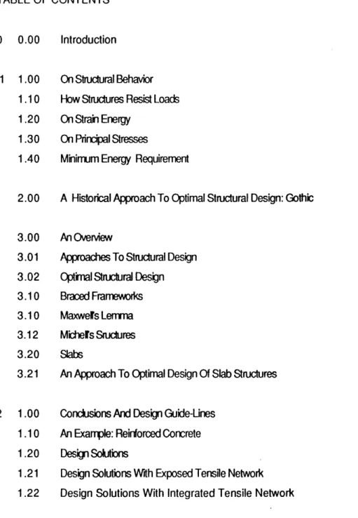
Studies of elasticity by Hooke Strain Energy -Area Under Stress-Strain Curve - 0.5se
material so that Hook's law "as the extension so the force" is not obeyed completely. For gradually loaded materials the stress starts at zero and builds up until the material is fully streched. The stored strain energy at each point can be calculated with the following formula:
Strain Energy = 0.5(stress)(strain) = 0.5se
1.30 ON PRINCIPAL STRESSES
The stored strain energy within any material to which loads are being applied can ultimately be used for its self-destruction or fracture. In effect, the fracture of a material in tension is primarily not due to the forces applied from outside but is a result of the conversion of stored strain energy into fracture energy. In other words the tensile strength of a material does not represent the required force to destroy the bonds between the atoms or molecules of the material. J.E. Gordon points out that the maximum tensile stress to
Figure 4
b
Internal static equilibrium of a beam. Principal compressions (arch actions) are shown by full lines and principal tensions (catenary actions) are shown by broken lines.
pull the atoms apart is higher than the practical strength determined by means of ordinary tensile tests. In a conceptually similar manner, other energy-exchange mechanisms are used by matter to escape from exessively high compressive stresses. There is one basic difference between failure under compressive and failure under tensile-stresses which needs to be pointed out. Concerning the tensile fracture process "it is broadly true to say that when a sufficient number of interatomic bonds have been stretched beyond their breaking point the material itself will break"(3).A direct analogy of this behavior can not be observed in
failure under compressive loads, since the resistance between atoms increases indefinately as the
compressive stress is raised. The only case where the compressive resistance between atoms colapses can be observed in the case of Black Holes where matter is subjected to enormous gravitational forces within these stars.
However, we know that matter does fail under excessive compressive forces. In most of these cases the actual form of fracture is due to shearing or other mechanisms of failure (such as buckling) in which the material finds a way to escape from exessively high compressive loads.
As we can see from this description the amount of stored strain energy for any given mechanical load is of significant importance for the structural behavior of the material. When a homogenous and continuous solid is loaded, a specific organization within the body is achieved to transfer the forces according to one very important rule in nature which is that the total work done (in this case the total strain energy stored) is always minimum. W. Zalewski states that "it means that it (the stored strain energy) is less than the energy or work which might be associated with any hypothetical -statically possible- force distribution in the same structure under the same load"(4).Implied in this statement is the observation that the change of shape or loading conditions will result in a reorganization of the flow of forces. W Zalewski compares the interior of a body to a "cavernous three dimensional (different in each case) arena on which forces play their particular games according to the available space always following the same rules" (5).
Figure -4 shows a simply supported beam subjected to three different types of loading conditions: a) Distributed linear loads
b) Two concentrated loads symmetrical to the center of the beam c) One concentrated load asymmetrical
The diagrams demonstrate how for each case the internal flow of forces assumes a different shape.
1.40 ON THE MINIMUM ENERGY REQUIREMENT
Following is a demonstration of the co-relation between the flow of forces and the stored strain energy that is related to each specific case. In a comparative analysis of two cases it will be shown that depending on the assumed distribution of force trajectories the calculated stored strain energy will vary considerably in magnitude.
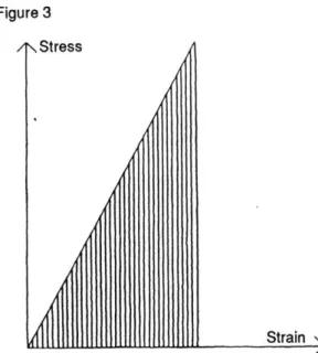
The comparison executed by W. Zalewski during a thesis meeting is based on a wall-like plate simply supported at the two lower corners. The sides of the plate are described with a and b with a<<b. The thickness of the plate is assumed to be one measurement unit. The plate is subjected to static vertical
loads which are concentrated in an area of a = 0.1a. The supporting surface at the corners is assumed to be 1/20th of a on either side.
Analytically and experimentally it can be shown that there is a natural tendency in such bodies to produce a linear distribution of internal forces starting beyond the immediate range of the source of loading action. The range of such linear distribution in our case is assumed to be h.
Given this case which corresponds to the true behavior of the plate, a hypothetical organisation of internal forces is constructed which is represented under case 11. Here the internal forces are assumed to be concentrated in a vertical strip which corresponds to the continuation of the loading force. The height of the strip is h while the width is a = 0.1a.
Following is the calculation of the stored strain energy in both cases:
In one unit of material which is being subjected to mechanical loads the strain energy can be calculated as: Strain Energy = 0.5(Stress)(Strain)
Figure 5 - Figure 6
List of symbols and relations: E : Young's modulus W : Strain energy f : Stress e : Strain E =f/e e =f/E W 0.5f2/E Calculation: Case I
The sum of strain energy in one unit of body is:
W = d2/2E
The sum of strain energy in the portion of body with assumed linear distribution is:
1W = 0.5ahd2/h
Case Il
W= 0.5(a/10)h(10d)2/E
= 10(0.5ahd2/E
Although this comparison is not definite proof of the fact that the linear distribution satisfies the minimum energy requirement, it clearly shows the advantage of this specific internal force organisation in relation to the one assumed in case 11. By linearly distributing the forces over the entire cross-section the material
stores only one tenth of the strain energy which it would have stored in the second case.
We may conclude that the knowledge concerning the flow of forces represents a most suitable tool in the design of structural forms when the objective is a more efficient use of material properties. Nature, in its 'designs' shows remarkably close transfers of force distribution patterns to physical forms. Bones of mammals represent a good example where the cancellous tissue is organized in a manner which resembles the flow of forces in these structural members. Also, designers have utilized the knowledge of flow of forces to arrive at structural design solutions. The importance of this approach is pointed out by Eduardo Torroja in his book Philosophy Of Structures. Refering to the designer, Torroja states that "...(finally) he will learn that it is not so ddifficult to draw a logical sketch of an isostatic network if a little thought is given to the theory and interest taken in the approach to such problems"(6).
2.00 A HISTORICAL APPROACH TO OPTIMAL STRUCTURAL DESIGN: GOTHIC
Unlike any other style in the history of architecture, Gothic has aroused a series of contradicting arguments among professionals and historians. Starting with Violet le Duc, Ruskin and Pugin in the nineteenth century, the variety of opinions on gothic ranges from those who see it as a result of rationality to those who approach it from a pure romantic point of view. The very existence of this ongoing argument, however
indicates the remarkable balance the Gothic Masters must have succeeded in achieving between technical solution and design. As R.J. Mainstone states in his book Development In Structural Form, "The result was an entire structural system in which structure, construction and visually expressive form were for a hundred years or so virtually undistinguishible"(7).
My second reason for choosing Gothic as an example is due to the fact that it represents a unique attempt
on such a large scale to achieve what we today consider as optimized structures. In terms of structural innovation, the twelfth and thirteenth centuries' level of productivity was not again reached until new technologies were introduced into the building industry at the beginnig of the first industrial revolution in the nineteenth century.
Today we can only speculate on the driving force behind the Gothic Master's striving to reduce the mass of masonry structures, the only material available to him. As intriguing, however, is the question of how
exactly the medieval masters managed to reach such structural perfection without any theoretic
knowledge on Structural behavior. Even the concept of force was not known to the designer and builders of gothic structures. R. Mark in his book Experiments in Gothic Stuctures, points out that, "Surviving fragments of building accounts indicate, that the medieval mason was unfamiliar with even simple
multiplication which explains the prevelance of geometry in design rather than any form of arithmetic
computation.(8)". Although the answer to the raised question will be speculative , I will introduce some of the ideas conceming the methods which may have been used by the medieval masons.
One of the factors wich must have eased the problem is inherent in the very technique used to build all gothic structures. Unlike other building techniques masonry is as J.E. Gordon points it out, the only one in which blind relience on traditional proportions will not automatically lead to disaster. The stresses in masonry are so low that the masons could afford to go on scaling up their buildings. Within the range of such small stresses, Gallileo's square and cube law doesn't need to be considered. Since the structure will not fail due to material failure, its strength can be predicted from previous experience or by scaling up from models. The main reason for failure in such structures is unstability and we may assume that models must have been built to predict the behavior of new structural elements.
The common building sequence must have been another factor favoring experiments throughout the construction process. Since the masons proceeded by completing the construction of one bay at a time, the design of the remaining bays could be improved based on the experience accumulated during the previous stages within each project. Cracks in the completed building parts could have indicated higher concentrations of tensile stresses which then could be eliminated through design modifications.
The list of methods which might have been used by the medieval masters could be further extended and elaborated. As a final point, however, I would like to introduce one last reason which may explain the success of gothic masters on a more conceptual level. In effect, we can assume that man has an intuitive ability which contributes to the development of optimized structural forms. Examples of this phenomenon can be observed in past civilizations however primitive they may have been. The development of
sophisticated theory frequetly serves to prove the efficiency of existing forms. The acceptance of this
statement will give further justification to the assumption that it is indeed possible to make a significant
contribution in the field of structural design coming from an architectural background.
Figure 7
Well and Reims cathedrals. Comparative nave cross-section indicates the vast difference in the scale of the structures of these two characteristic buildings.
3.00 AN OVERVIEW
In this chapter I will give an overview of optimization approaches to structural design. The first part focuses on those concepts which deal with a particular form of construction known as "braced frameworks".
Mentioned here are three main reasons which in general, make braced frameworks a particularly suitable tool to initiate concepts of optimization or structural theory :
The first reason concerns their wide range of applications. In almost every field of engineering we can observe designs which utilize basic concepts of truss-like structures. Secondly, braced frameworks can be considered as a construction form of relative simplicity. This characteristic simplifies the task of demonstrating methods of structural analysis and synthesis. Third, all issues which will be mentioned in relation to braced frameworks are applicable to more complex structural forms such as plates and shells. Two main approaches to optimal design of frameworks will be discussed in this first part which are "Maxwell's Lemma" and "Michell's Structures". In both methods the stuctural behavior within the elastic
range is observed.
The second part of this chapter deals with analysis methods which relate to the optimization of slab structures (eg. horizontal plates) -the main topic of this thesis. Here I will use the above mentioned analogy between braced frameworks and more complex structural forms, in this case slabs, to explain a specific approach concerning optimal design of highly indeterminate structures. The method I am referring to is based on the analysis of structural systems assuming ultimate loading conditions. Thus, in contrast to the approaches concerning braced frameworks the elasto-plastic range will form the point of focus.
3.01 APPROACHES TO STRUCTURAL DESIGN
The conceptual design of a braced framework or any other structure must start with the determination of the function the structure has to fulfill. In terms of the analysis the minimum information needed is the specification of the forces the structure has to transmit. In order to solve such problems there are two basic approaches to structural design which both depend on scientific methods. Following is a brief discussion of both concepts:
In the traditional method the engineer first assumes a structural system and analyzes it as to whether it satisfactorily fulfills the required set of functions. The designer can then go back to the initial model modify it, and analyze the new version. This process is repeated until the engineer is satisfied with his proposed
solution.
This approach which is called the 'indirect' or the 'analysis method' strongly utilizes the experience and knowledge of the structural engineer since the performance of the resulting concept mainly depends on his or her initial guess work. The disadvantages of this approach are obvious. We must first of all consider' the waste of energy involved in consequtive computations of the same problem. Secondly the resulting proposal, even if it satisfies the initial requirements, may not necessarily represent an optimal solution. The other approach, known as 'synthesis', deals with the determination of the best possible structure to
fulfill a given function or a set of functions. In traditional engineering this method is seldom applied and the developed theory to solve such problems seems to be rather limited. This is in part due to the complexity of structural problems where the influencing set of components may vary considerably from project to project. However, for some clearly defined cases, methods exist which can be applied to "synthesize" the optimal solution.
3.02 OPTIMAL STRUCTURAL DESIGN
The optimal structure, as W. Zalewski points out, "is the one that does the best over-all job in minimizing the undesirable characteristics, such as for instance weight, cost, time of construction, maintenance troubles etc." (9). In this broad sense there are very few cases in structural design where an obvious criteria exists which lends itself to rational optimization techniques. An example for such a case is the design of simple tie-bars where it would make little sense to use more material than absolutely necessary. Here, weight of the material represents the obvious criteria which can be minimized, thus optimized. Even in the context with various other criteria, weight of a structure remains a key factor which significantly influences the above mentioned general characteristics of structures. A number of advantages can be achieved as a
consequence of minimized weight, for example: decreasing the cost of the structure as a result of
minimized material consumption, and/or a simplified erection process due lighter components, etc. Given weight optimization as the primary design consideration, the designer can utilize techniques to predict the perfect structural form for the specific problem if the the set of extemal loads, their direction and points of action are specified. For a restricted number of such cases the theoretic background exists to assist the designer in the "synthesis" of optimal solutions. In the context of this thesis the term optimal design is used to describe the conceptual design of structures which achieve the required behavior at the smallest possible material volume (eg. weight).
L A V/(PL/f)
0
AB
0
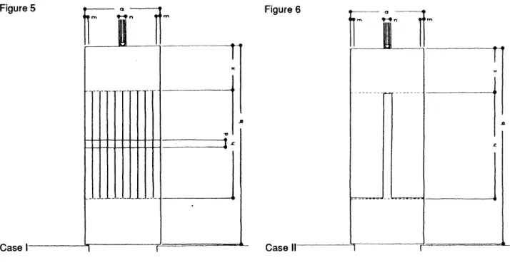
P Graphic representation of the relation between
Lay-ut f te oservd srucuresag-span ratio and volume. Minimum volume is reacheo
Lay-ut f te srucureat oservd S/L = 0.5.
The observed structure consists of a cable restrained at points A and B and loaded in the center by a vertical force P (Fig.8). The volume of the material needed to safely support load P is equal to the length of the cable multiplied by the area of its cross-section.
We can predict that with the increase of sag S the length of the cable will increse and at the same time the
the necessary cross-section will decrease. This statement can be reversed for the case when sag S is
reduced. The problem, here, is to find that particular sag-span ratio of the cable supporting load P, which corresponds to its least possible volume (eg. weight). The analytical solution of this problem can be found
in W. Zalewski's Classnotes. on the above mentioned pages. Figure-9 shows the graphical representation
of the results.
The curve of relation between sag-span ratio and volume is practically flat for values of S/L close to 1/2 (the theoretical optimum). It indicates that changes of S/L of the order of even 20%-30% from (S/L)OPT result in only small deviations of V from its minimum value. Therefore the whole range of values of S/L between 0.35 and 0.65 can be practically considered as corresponding to the minimum volume of cable.
3.1 BRACED FRAMEWORKS
Braced frameworks are trusslike structures with straight elements which resist the loads by change of their length. In other words the primary effects of load on such structures results in axial forces -eg. tension and
compression.
In its idealized form, the jointbetween two members is assumed to be loosely pinned. However, in reality in order to simplify the assembly process, braced frameworks are in most cases produced with rigid joints.
According to the theory of braced frameworks the resulting bending is neglected in the execution of
structural analysis. We can explain this by observing the deflections which occur in non-braced framework and comparing them with the deflections of braced framework. As we can see from figure-10 the magnitude of deformation in a braced framework is much smaller than the deformation in a comparable frame when subjected to similar loads. In terms of resisting the applied loads the contribution of bending moments to the axial forces within the members is insignificantly small. As a result of this the engineer in his
or her analysis may assume the idealized concept with pinned joints to simplify the computation. We may
conclude that in figure-10 the frames shown under (b) essentially resist the loads in the same way as the group under (c).
Following are the desciptions of two general theorems which can be applied to determine the shape of minimum weight networks. As mentioned in the introduction of this chapter, the methods in this first part
Figure 10
a
b c
Types of frame:
a-) Non-braced frames, b-) Braced frames with pinned joints, c-) Braced frames with rigid joints
are applicable only to 'braced frameworks' subjected to loads corresponding to their elastic range. I will restrict the explanation of these approaches to their general characteristics rather than their mathematical background which can be found in various publications (see references).
3.4 MAXWELL'S LEMMA
The first theorem which dealt with single-purpose structures was developed by Clerk Maxwell and
published in 1869 (Clerk Maxwell, Scientific Papers 11, p.175). It is known as Maxwell's Lemma and represents a usefull guide in a very restricted number of cases to determine the optimal shape.
Maxwell's Lemma:
atVt -ac Vc = constant
members, Vt the total volume of all the tension members and Vc the total volume of the compression members. From this equation it can be seen that in order to achieve a minimum weight network ,either Vt or Vc must be minimised. Since the smallest value these two expressions can assume is zero, it follows that if we can design a network in which all members work either in tension or in compression the resulting structure will be of minimal weight. Furthermore, the weight of such a structure is independent of its geometry since all structures which fulfull the first requirement will assume the same weight (ignoring the weight of the members end-fittings).
As H.L. Cox states it, one drawback of this approach is the fact that, "Although the theory indicates the lay-out most apt to the loading specified, it fails to discriminate between structures as the engineer understands them and mechanisms" (10). Another disadvantage is the relatively small number of cases where it is possible to design a network with all its members either tension or compression. For those cases where such a framework will not equilibriate the external forces, Michell's approach can be used to establish the minimum weight structure.
3.5 MICHELL'S STRUCTURES
A.G.M. Michell specified the criteria for minimum weight networks in a publication titled "The Limits Of
Material In Frame Structures" in 1904. His concept, which is derived from the theory of self-consistent
fields of strain, remains to be the most important source in the investigation of absolutely optimum
structures for given conditions of loading. It also provides ideal norms against which the performance of other optimized designs can be meassured.
The basic requirement of Michell's Frameworks is the following:
The framework S' within the domain D' must provide that the strain along all tension and along all
compression members (regarding each group seperately) is constant. Furthermore, the absolute value of the compressive stress never exeeds in magnitude the value of the tensile stress. This statement, of
which the mathematical proof can be found in E.W. Parkes' book "Braced Frameworks" (ch.5, p.166-167), imposes the geometric configuration of Michell's minimum volume structures.
The first rule concerning the geometry states that the configuration of the members, both those in tension and in compression, must be such that they always meet perpendicularly. They preserve this orhtogonality in deformed state.
There are many forms of networks satisfying the above mentioned criteria. However most useful for practical design solutions are the following three cases:
a) the rectangular b) the equiangular spiral c) the circular
The second group is descriptive of the general characteristics for a number of networks. This group, depending on the loading conditions, can be created of spirals, ellipses, cycloids and /or a combination of
these.
Figure 11
a b c
Nets extending to most of space: a-)rectangular, b-) equiangular spiral, c-) circular fan. These nets form also the basis for diagrams of flow of forces.
When we observe the shapes of Michell's networks an obvious similarity to diagrams of principal stresses will strike us. This is not accidental since, as W. Zalewski points out, "The same basic nets provide the geometrical background for practically all possible modes of transfer of internal forces through bodies of solid structures"(1 1). In effect Michell's diagrams can be considered as representations of principal tensile and compressive stresses of continious bodies under mechanical loads. The following diagrams may help to demonstrate this analogy. The first column represents the force trajectories in infinite vertical loads , of one unit thickness, when subjected to the shown loading conditions. The diagrams on the right give
Michell's solutions corresponding to these cases (Fig.12).
Two further characteristics of Michell structures should be mentioned here. Compared with any other structure resisting the same loads and assigned into the same domain, the Michell Structure will not only consist of the least volume but will also absorb the least amount of energy. Furthermore, it will represent the stiffest (eg. least deformable) of all possible, comparable, networks under the same conditions (For
analytical proof, see Classnotes, W.Zalewski, p80). It is significant to observe in these statements the
Figure 12
9
7
Lines of forces in half-plane vertical narrow strip (left drawing) and the corresponding Michell's Structure (right drawing)
co-relation between the specific problem of minimum weight structures and the general rule of minimum energy requirement in nature as mentioned in part 1.40.
The approach to structural design with Michell networks can be carried out in two basic cases. Those nets which extend to the whole of space will result in a framework which will represent the solution of absolute minimum volume. However, also for frameworks within a restricted domain D, Michell's method will provide us with the geometry of the mininimum-volume-structure within D. Following is the comparative analysis of two cases solved by H.S.Y. Chan (Half-plane Slip-line Fields And Michell Structures, 0. J.L. Mech.Appl. Math. 20,1967). In figure-13 the first diagram represents the unrestricted domain solution, while the second geometry is the result of the same problem when restricted to lie in a half plane. It should be pointed out that the volume of the solution within the restricted domain D is in magnitude higher than the volume of the framework obtained in the unrestricted domain.
The application of Michell networks to practical design problems brings up the issue of joinery between the members of the framework. Since these networks only represent the optimal solution in regard to the
Figure 13
Restricted and unrestricted domain solutions for Micell' Structures as developped by H.S.Y. Chan. The solution on the left represents for the specified problem the structure of absolute minimum volume. The diagram on the right gives the solution for the case when the structure is restricted to a half Plane.
geometric organization of the structure, the designer must pay special attention to the number and weight of the joints in the final concept.
In the case of a framework which consists of bars, it may be advantageous to choose a geometry with fewer but as a result of this heavier elements. The consequence is a reduction of the number of joints in the structure. We may conclude that the over-all contribution of the joints to the total weight of the framework
will also be reduced. On the other hand, it may be more reasonable to chose a solution with a relatively
high number of members. In this case due to the smaller stresses within the members lighter joints may prove to be sufficient.
If instead of a bar-framework an integral construction (eg. casting, perforation...) is applied the issue of
joinery, thus joint-volume, does not arise. The stress concentrations at meeting points of members
become the major topic of consideration. In this account, it is obviously better to use a framework with a high number of light ribs.
As we can see from these explanations the designer should be aware of trade-offs his or her decisions
involve with regard to the structure's over-all weight. The complicated geometry of these structural
concepts require in the design phase a high level of skill and attention to detail.
In general, Michell's theory has found little practical application in architecture and structural engineering
practice. This may partially be due to the complicated geometry as I have mentioned it in the previous
paragraph. Also the amount of space that is essential for absolutely minimum networks makes these
solutions impractical. Another, and more relevant reason should be seen in the limitations of the theory.
Michell's approach can be applied only to loading systems which must wholly lie in a single surface and where the loads act in the same plane of the structure. A change in the direction of the loads is sufficient to make the geometric solution invalid. Even for those cases which completely satisfy the requirements of the theory, instability of the resulting structure remains an issue since Michell's approach doesn't consider the problem of buckling.
Although Michell's Structures in their pure form may not be of significant practical importance (for structural design problems with weight optimisation as the main issue) the networks provide valuable guidence. W.
Figure 14 a c F---1 P/2 P P/2 P/2 P P/2 b
Three geometrical arrangements of trusses with the same depth/span ratio. The load in all cases is applied in the center of the structure. The first diagram shows the flow of forces in a corresponding continuous beam.
Va= 4.98 PUf, Vb= 3.50 PL/f, Vc= 3.37 PUf
Zalewski, in his classnotes, demonstrates that as the lay-out of a truss comes closer to the outline of the comparable Michell's solution, its volume decreases.
Above are three examples of single-span beam structures which are subjected to the same loading conditions (Fig.14). In all cases the structure is limited to the same spatial domain as the corresponding solid beam. The third configuration is designed in close reference to the minimal weight solution and has the least volume.
As we can see from these examples, even for spatially limited domains the stress fields in the corresponding solid beam or the Michell's solution for the given restricted domain, as W. Zalewski states it,
"...may serve as an inspiration and guidance in design for low weight."(1 2) Due to the correspondance
between the flow of forces and optimal design layouts we have two options in the approach to weight optimisation. We can either rely on systematic optimisation methods like in the case of Michell Networks or as W. Zalewski ponts it out, "One can take also another direction and design an optimum framework on the basis of known field of stresses in the solid body"(13).
Figure 15
Slab structure subjected to distributed loads: a-) Simply supported along the edges, b-) simply supported at the four corners. The directions of principal bending moments is marked by dotted lines on the top surfaces.
3.20 SLABS
The form of the slab is characterised by its major horizontal surface and its relatively small thickness in the third dimension. In contrast to the braced frameworks, of which the components are subjected to axial forces, only the slab is bent multidirectionally.
We may distinguish two basic groups of slabs:
Those which span only in one direction can be considered as a system of single beams. However, the special structural quality of slabs result from their ability to carry loads in various directions. Regarding "the internal actions in transmitting loads to the supports", R.J. Mainstone states that, "They may then be roughly visualized as those sets of very flat doubly curved membranes within the thickness of the slab"(14). The membranes may be seen as spatial (3-D) representations of diagram of internal forces.
These imaginary membranes, e.g. diagrams of forces, will shift and assume different geometries corresponding to the changes in the distribution of the loads. For each specific loading condition the form of the internal force distribution will satisfy the minimum energy requirement. The figure-15 shows the -principal bending moment as projected to the surface of the slab for two different support conditions. Solid slabs in general are not efficient in terms of utilizing the available material of the structure. The stresses in these structures vary considerably in magnitude over the entire cross-section and much of the material is stressed only to a small degree.
As a final remark it should be stated that slabs represent intemally, highly indeterminate structures. In the elastic range the conditions of equilibrium are usually not sufficient for the exact determination of force
distributions.
3.21 AN APPROACH TO OPTIMAL DESIGN OF SLABS
In the following I will focus on an optimal design technique for slabs. As I have mentioned in part-3.12 the approach that will be discussed here is not of the general nature, like Michell's method.
Indeterminate structures, when subjected to actions which come close to ultimate loads change their structural behavior. It can be shown that while the conditions of equilibrium are not sufficient to analyze these structures within their elastic range, they can be applied for the analysis when the elasto-plastic range is assumed. Therefore this method is only applicable when the analyzed structure is made of a material which provides elasto-plastic behavior. Considering that steel (a most important building material) has the needed ductile property, we may state that this restriction does not weaken the relevance of this approach for purposes of structural analyses. As it is known, reinforced concrete structures when reinforced within certain limits, also demonstrate the required elasto-plastic behavior.
Various methods utilize the above described phenomenon in the solution of optimization problems concerning highly indeterminate systems. Here, I will focus on G.I.N. Rozvany's approach which he calls
Optimal Design of Flexural Fields and which has been published under the same name. According to
G.I.N. Rozvany his method can deal with the optimal design of various types of reinforced concrete
structures, subjected to bending such as long-span-beam systems, prestressed plates, reinforced conctrete slabs and space frames. G.I.N. Rozvany points out that "For plane systems with almost any
boundary conditions Optimal Flexure fields give both maximum strength and maximum stiffness for a given material volume when the depth is constrained"(15).
The problem G.I.N. Rozvany's approach is dealing with can be described as follows:
Find the lay-out of reinforcement resulting in minimum amount of steel for a slab of constant depth, -the contours may vary- subjected to a system of vertical loads which are to be transmitted to specified free, clamped or simple supports. The transmission of loads can be explained by assuming beams within the slab, as is the case in grillages.
Following is a comparative list of characteristics between Michell's Structures and Optimal Flexure Fields:
Michell Structures Optimal Flexure Fields
applicable in the elastis range applicable in the elasto-plastic range
applicable to trusslike structures applicable to continious structures
deals with cases in which the plane of the loads loads are normal to the plane of the structure coincide with the plane of the structure
total volume of the resulting structure is total volume of reinforcement is
minimum minimum
It is important to note here that while Michell's networks deal with the determination of the optimal structural form, in the case of the G.I.N. Rozvany's approach, the over-all form of the structure is given. The main question here consists of reducing the amount of reinforcement in the structure.
based on the behavior of structures made of ductile materials in the stage of ultimate resistence.
Before considering the behavior of horizontal plates under ultimate loads, the case of a 3-bar-framework will be used as an example to demonstrate the characterised change of behavior as loads come closer to their ultimate value.
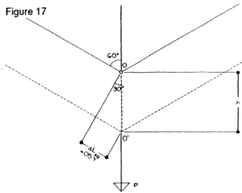
Consider that the vertical load W is applied to a joint 0 of the framework:
Considering the elastic range where stresses are proportional to strains we can determine the forces each member is subjected to. We know from the law of compatibility of deformations that the structure must assume the shape as represented in figure-17 with dotted lines.
List of the bar-lengths: LBO = L
LAO = LCO = LBO/sin3O0 = UO.5 = 2L
As a result of the systems specific geometry the increase of the length in each bar is as follows: ALBO =
ALAO = ALCO = sin300ALBO =sin300Y
ALCO = ALAO = 0.5SLBO = 0.5Y
The resulting relative deformations (strains) of both inclined members are:
eAO = eCO = ALAO/LAO =0.5Y/2L = 0.25Y/L
The deformation in the vertical member is: eBO = Y/L
The relation of the stresses between the vertical and the inclined members is:
eAO = eCO =0.2 5eBO
In other words inclined members are subjected to stresses which are in magnitude only one-fourth of the stresses in the vertical member (when the angle between the vertical and horizontal members is 600). We may conclude that the geometry of the three-bar-framework and the elasticity of all its parts determine
the relation between strains and stresses in its members. Furthermore we see that this relation is independent from the magnitude of the member's cross-sectional area. But forces in members do vary depending on the area of cross-section. W. Zalewski points out that, "This is a characteristic situation in
structures called statically indeterminate, in which forces are not only governed by requirement of equilibrium but also by conditions of geometrical compatibility"(16). This statement is valid for all three-bar-structures when observed within their elastic range. The geometric condition determines the
above mentioned ratio of stresses between the inclined members and the vertical member. In our case it is1:4. Since the equilibrium conditions are not sufficient to analyze the internal forces, all such structures must be considered statically indeterminate.
If we continue to load the structure until the stresses in the vertical member reach Fy, the "yield stress", we
shall observe a change in the behavior of the framework. If from this point on the load continues
increasing the forces within the vertical member will remain constant since the member will start to deform plasitically. At the same time, the stresses in both inclined members will increase until, they too, reach the
Figure 16 Figure 17
Lay-out of the observed structural system. The dotted line represents the structure in its deflected stage.
Diagramatic close-up of the part of cable to which the force is being applied. The diagram also represents the
trigonometric relation between the increases of length in each bar.
"yield stress". Thus, when all three members reach the elasto-plastic range we predict the stresses in each member must all be equal. Since the force in a bar is equal to the product of stress and the
cross-sectional area, and since depending on the material we use the yield stress is given, we may
determine the force in the member. Assuming that in our case all three bars have the cross-sectional area the calculation is as follows:
Tv : Tension in the vertical bar
TINC : Tension in the inclined bars fy : The yield stress
A : Cross-sectional area of the bars TV = TINC = A fy
We can also calculate the load P'E-P which represents the ultimate load the three-bar-framework can support since it must be equal to the sum of the vertical components of all the internal forces involved.
P'E-P 0.5A fy + 1A fy + 0.5A fy
= 2A fy
The total cross-section is:
A = P'E-P/2 fy
Knowing the cross-sectional area we can calculate Vt, the total volume of the framework, by multiplying the total area with the total length of the bars:
Vt = A (2L + 1L + 2L)
with A= P'E-P/2 fy
Vt = 5P'E-PU(2 fy)
We can now compare the three-bar-framework with an alternative structure which consists of one tension bar subjected to the same load
P'E-P-The cross-sectional area is:
A = P'E-P/ fy
The total volume is: Vt = A I = P'E-PUify
As we can see the ratio of volumes between the two alternatives is 1 : 2.5. The first framework is 2.5-times
heavier then the second configuration. Incidentally, the one-bar-framework represents the
minimum-volume solution for the given conditions.
As we can see from this example, the assumption that the structure is loaded until all its members have reached the elasto-platic range enables us to analyze the system using simply the rules of equilibrium.
Following is the demonstration of the same approach in the case of a rectangular plate simply supported
Figure 18 Figure 19
l
AI
Diagram of the one-bar structure subjected to load P
Diagram showing the internal force distribution in the three-bar framework.
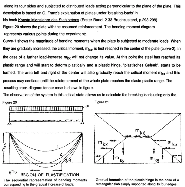
along its four sides and subjected to distributed loads acting perpendicular to the plane of the plate. This description is based on G. Franz's explanation of plates under 'breaking-loads' in
his book Konstruktionslehre des Stahlbetons (Erster Band, 2.33 Bruchzustand, p.293-299). Figure-20 shows the plate with the assumed reinforcement. The bending moment diagram
represents various points during the experiment:
Curve-1 shows the magnitude of bending moments when the plate is subjected to moderate loads. When they are gradually increased, the critical moment, mkx, is first reached in the center of the plate (curve-2). In the case of a further load-increase mkx will not change its value. At this point the steel has reached its plastic range and will start to deform plastically and a plastic hinge, "plastisches Gelenk", starts to be formed. The area left and right of the center will also gradually reach the critical moment mkx and this process may continue until the reinforcement of the whole plate reaches the elasto-plastic range. The
resulting crack-diagram for our case is shown in figure.
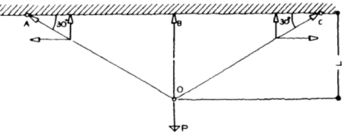
The observation of the system in this critical state allows us to calculate the breaking loads using only the
Figure 20 Figure 21
H11II I
11EElII[Hu1III1I u11.w
r1
RE.GION OF PLASTIFICATION
The sequential representation of bending moments corresponding to the gradual increase of loads.
Gradual formation of the plastic hinge in the case of a rectangular slab simply supported along its four edges.
conditions of equilibrium. Since we assume hinges along the cracks we can now represent the system as shown in figure-21.
Using the above described method as a basis G.I.N. Rozvany in his book Optimal Design ofFlexuralFields gives the optimal lay-outs of reinforcement for various shapes of slabs. For a given shape of slab-structure various yield-line diagrams can be assumed and the ultimate moment along the hinge can be calculated using only rules of equilibrium. These are now sufficient to determine the forces within the system, since with the introduction of the plastic hinge the system ceases to be an undeterminate case. The calculations will show that for different yield-line diagrams varying values of ultimate moments will result. The problem at hand is to determine that specific organization which will result in the minimum total ultimate moment (e.g the minimum sum of bending moments in all sections).
Figure-22 shows his solutions for square domains with varying boundary conditions. To interpret these diagrams a list of sign descriptions is given. Within the neutral -zone the direction of reinforcement can be freely chosen. For all other areas the direction of the negative or positive bending moments should be
Figure 22
Optimal Flexure Fields for square domains:
-Free edge CD
=Simple support
- Clamped edge
<-Direction and sign of non-zero moment
considered in the design of the reinforcement.
Following are two lay-out plans for reinforcement of a square slab from an experimental project executed by G.I.N. Rozvany. The observed slab is simply supported along its edges and thus. corresponds to the first scheme presented in figure-22.
These lay-outs of reinforcement help to give an idea of how to transfer the diagramatic representations of flexural fields into the design of reinforced concrete slabs.
For slabs of any shape which are simply supported along their edges, W. Zalewski proposes the following approach of analysis:
In the first step a circle is inserted int the shape of the slab so that the edges of the slab form tangents to the circle (Fig.24).
The bending within the circle can be calculated as: M = qR2/6 or
= qr2/24
Figure 23
a b
Two types of reinforcement which both correspond to the optimal lay-out as determined by G.I.N. Rozvany: a-) Minimal reinforcement with one way action in corners, b-) Minimal Reinforcement with two way action in corners.
Total load along the peripheri of the central slab portion is:
QTot = qnR2 = 0.25qnr2
Reaction force per meassurement unit along the peripheri of the circular slab is:
p = QTotr/(2nR) = qnr2/(2nr) = qr/2
This central slab section is assumed to be supported by beam-like strips within the thickness of the slab forming tangents to the central circle. The forces these beam-sections are subjected to can be calculated like a normal beam which is subjected to forces resulting from the two triangular fields adjacent to the strip. MTot = MF1 + MF2
= qrl2/16 + QF21/6
As we can see from these examples the consideration of structural behavior within the elasto-plastic range
simplifies the analytical analysis of indeterminate structures significantly. This method represents an opportunity for dessigners to calculate the forces which can be expected in their structures and make
plausible estimations. Figure 24
FIELDI MELDI
Diagramatic representation o fthe observed structural system in plan-view. A slab of irregular shape simply supported along its edges and subjected to distributed loads.
1.00 CONCLUSIONS AND DESIGN GUIDE-LINES
Following are concluding remarks on approaches for optimal structural design and the presentation of design guidelines as they apply to the design solutions presented in this chapter.
In the first chapter of the thesis, Maxwell's Lemma and Michell's Fields have been revised. These methods may be considered as resulting from attempts to rigorously formulate minimum weight structures. Certain characteristics should be mentioned here which are common to both approaches. First the methods have been developed considering the behavior within the elastic range of structural material and thus do not cover the full range of the structure's load-bearing capacity. The restriction of the observation to the elastic range also results in highly analytical solutions. Second Maxwell's Lemma and Michell's Fields are, both, applicable to very restricted cases. It has also been shown that there is a significant co-relation between the results of these analytical techniques and the concept of flow of forces. In concluding this brief review, it can be stated that the phenomenological concept of force trajectories can be useful not only to better understand and describe structural behavior but also in the consideration and development of optimized structural design.
Gothic architecture may be considered as the manifestation of such an intuitive approach to structural design optimization. As stated in part 2.00, given the building material and technique, the gothic masters have been able to achieve, without any analytical concept, structures which come very close to optimal design solutions.
In part 3.20 it has been shown that the calculation of structural systems can be significantly simplified if instead of the elasic range (as is the case in Maxwell's Lemma and Michell's Fields) the elasto-plastic range of structural material is observed. The Ultimate Strength approach and Optimal Design Of Flexural Systems, which have been reviewed as an example to this method, clearly show the simplification that can
be achieved by assuming the formation of 'plastic hinges' within structurally highly indeterminate systems. Thus, we may conclude that it is possible to approach structural optimization on a conceptual level utilizing simple analytical tools and the knowledge concerning flow of forces.
Within the context of this thesis, optimal design of slab structures will form the focus. Three-dimensional grid structures, widely known as space frames, will be reviewed with the objective to improve the ratio of the load-bearing capacity to material consumption in existing systems and to propose new concepts. Space frames in their current form of construction have certain characteristics which negatively influence the system's structural efficiency:
- The load-bearing capacity of the joints define the limitations of the whole system.
- Since the system consists of only a few different elements most of the members depending on their final p,ositioning, are structurally overdesigned.
- The continuity of the elements is broken into a sequence of struts and hubs. Although within the compression members this interruption does not represent a serious draw-back, it is a problem when the tension zone is considered.
- Due to prefabrication methods which are applied in the production of these systems, the elements must have certain over-all dimensions. As a result of this the final structure must follow a certain modular grid which doesn't usually coincide with the diagram of flow of forces.
These disadvantages can be eliminated by introducing additional continious tensile elments into the basic framework. The concept, here, is as follows:
The added tensile members -eg. cables or bars- must be designed so that they take over the transmission of the tensile forces to a considerable degree when the structure is completed. This allows the basic framework to be of lighter nature. It must in the construction phase conceptually only provide the structural strength to carry its own weight. The full loading capacity is reached only after the basic framework and the tensile network form a unity. The continuity of the tensile members help to eliminate the above mentioned disadvantages of existing space-farme systems, concerning the interruption of force transmission through
The concept which is being addressed here is successfully utilized in the case of reinforced concrete where the two materials, steel and concrete, take over specific structural functions. Following is a description of reinforcement in combination with concrete. The basics of this method must be seen as guidelines for the reinforcement of three-dimensional steel frameworks.
1.10 REINFORCED CONCRETE
Throughout the history of architecture we can observe the application of wrought-iron in combination with masonry where the metal was used clearly for its high tensile strength in an attempt to neutrilize the tensile
deficiencies of masonry. A highpoint of this approach was reached in the beginning of the nineteenth
century when conscious efforts were made to design structures in such a way that the iron took over the tensile and shear forces while the masonry resisted loads in compression. R.J. Mainstone in his book.
Figure 25
,~
tT
~'. *Development of Structural Form gives as an example the portico of the French Pantheon and points out that , "In the neo-classical architecture of the eighteenth century France, such reinforcements were used so extensively in flat-arch-forms that imitated monolythic classical lintels, that the proportion of iron to stone approached that in some reinforced concrete beams"(17). According to R.J. Mainstone these examples can be seen, "...as a clear anticipation of reinforeced concrete"(18). A justification for this analogy may also be seen in the fact that concrete, like natural stones provides a tensile strength that amounts to approximately one tenth of its compressive stress.
The acknowledged beginning of reinforced concrete, as we know it today, goes back to the patent application of the French gardener Joseph Monier (1823-1906), who used concrete in combination with wire meshing in the production of flower pots. The development of this new composite material was made possible by Joseph Aspden's earlier invention of the first artificial cement. In his patent application which dates back to 1824 J. Aspden refers to his invention as "artificial stone" and calls this new product "Portland Cement".
The composite material "reinforced concrete" must be considered as a new material which has, in terms of its characteristics, basic differences in both of its components, steel and concrete. R.J Mainstone's description of this new building material is as follows:
"Reinforced concrete is an organically constituted stone in the mass of which the tensional function of the reinforcement is effectively distributed and arranged in such a way that the steel at every point will resist tension in accordance with the existent network of stresses"(19).
The officially acknowledged discovery of reinforced concrete's structural behaviour was established through a series of extensive experiments carried out in the last quarter of the nineteenth century in Germany. Supervised by M. Koenen 1849-1924), who also developed the first theory on the analysis of reinforced concrete structures, the results of these experiments showed that while concrete is responsible for absorbing the compressive stresses, steel only resists tensile stresses. However, the understanding of this mechanism must have been known by designers at an earlier time. A patent drawing by Wilkinson from 1854 shows the correct positioning of the steel cable within the body of a beam