FTL
COPY, DON'T REMOVE
33412, MIT
....02139
DECISION SUPPORT SYSTEMS FOR
AUTOMATED TERMINAL AREA
AIR TRAFFIC CONTROL
JOHN DEMETRIOS PARARAS
DECISION SUPPORT SYSTEMS FOR AUTOMATED TERMINAL AREA
AIR TRAFFIC CONTROL
John Demetrios Pararas
ABSTRACT
This work studies the automation of the terminal area Air Traffic Management and Control (ATM/C) system. The ATM/C decision-making process is analyzed and broken down into a number of "automation functions". Each of these functions is described with particular emphasis on its role in the overall system and its interactions with the other ATM/C automation functions. Runway Scheduling and Traffic Flight Plan Generation are identified as the two functions with the greatest potential for providing efficiency improvements over the current terminal area ATC system and are studied in detail.
A very general Mixed Integer Linear Programming (MILP) formulation of the Runway Scheduling problem is developed. Less general formulations and algorithms which have appeared in the literature are reviewed and evaluated. A heuristic algorithm is developed. The
algorithm is based on the work of Dear and adopts tne Maximum Position Shifting methodology proposed by him [DEA 76). It extends Dear's work in several ways: (1) it is applicable to multiple runway configurations. (2) it is designed to operate in a real-time simulation environment, and (3) it is designed to accept arbitrary constraints imposed by the ATM/C controller.
The methodology for generating flight plans is developed. Flight plans are based on a specified route structure. They are 4-dimensional and conflict-free. To allow maximum runway scheduling flexibility, a .specific route structure is proposed. It is designed to allow easy
modification of flight plans to adapt to the dynamically changing
schedule.
To allow algorithmic development and testing of this (as well as other) ATM/C automation concepts, a real-time terminal area simulation facility (called TASIM) is designed and implemented. The facility has a
number of characteristics which make it a good general purpose tool for terminal area ATM/C research:
(1) Highly modular design which allows addition, removal and
modification of functions with relative ease.
(2) Realistic modelling of the aircraft dynamics of motion and the aircraft guidance system. Errors introduced by the navigation equipment (onboard and on the ground) and
(3) Capability to simulate multiple controller positions
(4) Flexible controller interface which allows easy implementation
of alternative displays and alternative protocols for man-machine interaction.
The simulation is fully operational in the conventional (manual)
ATC mode. In addition, it is currently interfaced with an
implementation of the runway scheduling heuristic, and with a special purpose final vectoring display designed to aid the controller in precisely timing the delivery of landing aircraft at the outer marker.
Acknowledgement
Professor Robert Simpson has been a source of advice and inspiration throughout the course of this work. He has been the teacher who introduced me to the field of Air Traffic Control, and patiently relayed his vast knowledge on the subject over the last few years. He
has been the advisor who provided guidance when I most needed it, and at the same time allowed me the freedom to pursue my own ideas. Working under his supervision has been an extremely rewarding and pleasing
experience. For this I am deeply grateful.
Professor Amedeo Odoni has shaped my entire graduate career at MIT.
My admiration for his rare combination of academic achievement, teaching
ability, and deep love and respect for people, was immediate and has kept growing over the years. I feel privileged to have known him and to be able to call him my friend.
Professor Thomas Magnanti sparked and has kept alive my interest in mathematical programming and optimization. His inspired teaching and vaiuable guidance during my years at MIT are deeply appreciated.
I would also like to express my thanks to Gabriel Handler who introduced me to the field of flight transportation and is thus indirectly responsible for bringing me among the outstanding group of people which comprise the Flight Transportation Laboratory at MIT.
Finally, my wife Jan and my son Dimitri provided the stability which saw me through the difficult moments and multiplied my feeling of accomplishment during my successes.
The research for this project was performed at the MIT Flight Transportation Laboratory. Funding for the development effort was provided by NASA Langley Research Center through the Joint University Program for Air Transportation Research. (NGR-36-009-017)
-5-TABLE OF CONTENTS
Page
CHAPTER 1: INTRODUCTION 14
1.1 Background and Motivation 14
1.2 Overview of Previous Research 19
1.3 Document Summary 25
CHAPTER 2: FUNCTIONAL DESCRIPTION OF AN AUTOMATED TERMINAL AREA
ATM/C SYSTEM 29
2.1 Introduction 29
2.2 The Generic Terminal Area ATM/C System 30
2.3 The ATM/C Flight Plan Generator 38
2.3.1 Nominal Flight Plan Generator 40
2.3.2 Runway Scheduler 41
2.3.3 Traffic Flight Plan Generator 44
2.4 ATM/C Command Processor 45
2.5 The ATM/C Traffic Monitor 49
2.5.1 Conformance Detection and Resolution 49
TABLE OF CONTENTS (continuea)
Page CHAPTER 2 (continued)
2.5.3 Hazard Resolution Path Generator 52
2.6 Traffic and CTID Displays 53
2.7 The ATM/C Controllerts Role 55
CHAPTER 3: A SIMULATION TESTBED FOR THE DEVELOPMENT
OF ATM/C AUTOMATION SOFTWARE 57
3.1 Overview 57
3.2 The Hardware Environment 58
3.3 Major System Components and Interfaces 60
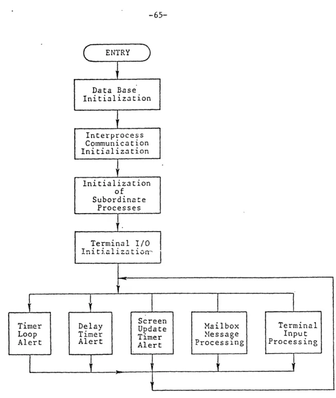
3.4 The Simulation Monitor Process 64
3.4.1 Data Base Initialization 64
3.4.2 Interprocess Communication 68
3.4.3 Subordinate Processes and Execution Control 70
3.4.4 Initialization or Terminal I/0 73
3.4.5 Timer Loop Alert 74
3.4.6 Delay Timer Alert 76
3.4.7 Screen Update Timer Alert 76
TABLE OF CONTENTS (continued)
-Page CHAPTER 3 (continued)
3.4.9 Terminal Input Processing 79
3.5 The Position Generator Process 81
3.5.1 Mailbox Message Processor 82
3.5.1 Traffic Generation Model 83
3.5.3 Aircraft Status Update and Handotf Processing 86
3.5.4 Aircraft Dynamics 87
3.5.5 Air Data System Update 88
3.5.6 Aircraft Navigation System 88
3.5.7 Surveillance System 89
3.6 The ATM/C Controller Process 91
3.6.1 Mailbox Message Processor 93
3.6.2 Command Activation 94
3.6.3 Traffic Display Driver 97
3.6.4 Input Editor 102
3.6.5 Input Processor 102
3.6.6 CTID Update 104
-8-TABLE OF CONTENTS (continued)
Page
CHAPTER 4: THE RUNWAY SCHEDULING PROBLEM 107
4.1 Introduction 107
4.2 Definitions 109
4.3 Formulation ot the Dynamic Runway Scheduling Problem 113
4.4 Measures of Runway Efficiency 117
4.4.1 Runway Capacity 11t
4.4.2 Aircraft Delays 120
4.4.3 User Cost Distribution: The CPS Methodology 125
4.5 The Complexity of the Runway Scheduling Problem 128
4.6 Variations ot the Runway Scheduling Problem 134 4.6.1 Scheduling Landings on a Single Runway (MPS=infinity) 135
4.6.2 Scheduling Landings on a Single Runway (MPS<N a-1) 138
4.6.3 Scheduling Landings on Independent Runways (MPS<N a-1) 143 4.7 Heuristic Versus Exact Algorithms 145 4.8 A Heuristic Algorithm for the Scheduling Problem 150
TABLE OF CONTENTS (continued)
Page CHAPTER 4 (continued)
4.8.2 The Feasibility Stage 154
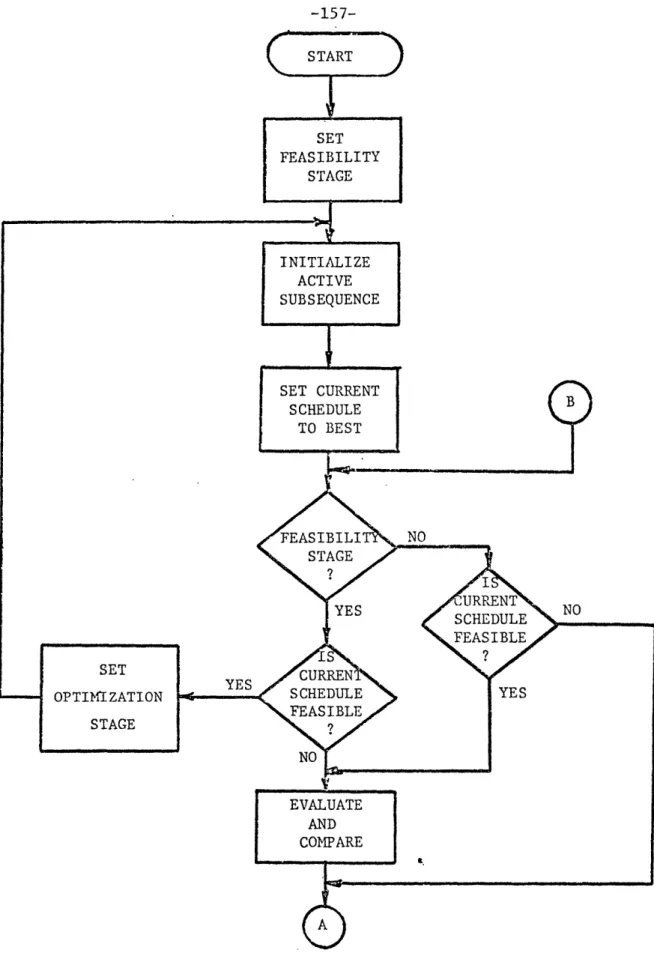
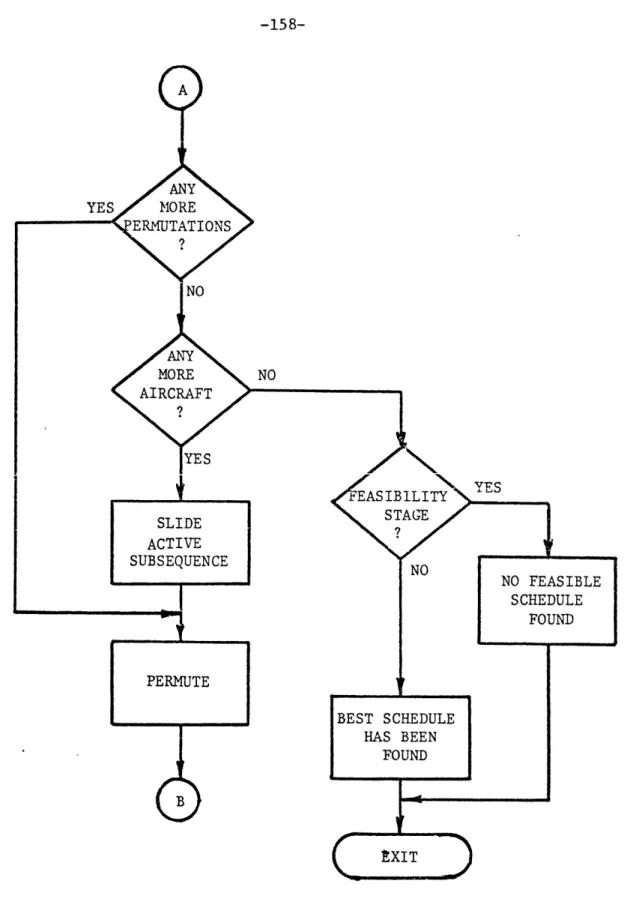
4.8.3 The Optimization Stage 156
4.9 Implementation Status 162
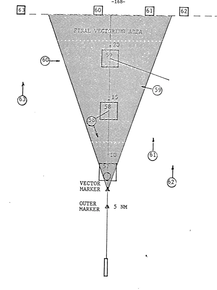
4.10 Coordination Among Terminal Area Control Sectors 163 4.11 Computer Aided Vectoring for Approach Spacing 166
CHAPTER 5: A IETHODOLOGY FOR TRAFFIC FLIGHT PLAN 171
GENERATION
5.1 Introduction 171
5.2 Flight Path Structures 175
5.3 Ground Track Selection and Speed Control 104
5.4 Altitude Selection 188
5.5 Conflict Identification and Resolution 189
5.6 The Base and Final Approach Phases 192
5.7 Aircraft Guidance 207
5.7.1 Recovery from Errors in the Execution of' Turns 207
-10-TABLE OF CONTENTS (continued)
Page
CHAPTER 6: CONCLUSIONS AND RECOMMENDATIONS
6.1 Summary
6.2 Recommendations for Future Research
APPENDICES
A Interarrival Dynamics
B The Kinematics of the Intercept Vector
REFERENCES 215 215 219 222 229 233
LIST OF FIGURES
Page 2-1 Overall Schematic Diagram of the Terminal Area ATM/C System 31
2-2 The Major Elements ot the Automated Ground Control System 35 2-3 Functional Block Diagram of the Automated Ground Control 39
System
3-1 Current TASIM Hardware Diagram 59
3-2 TASIM Software Processes 61
3-3 Top Level Flowchart of the Simulation Monitor Process 65
3-4 Timer Loop Alert Processing Detail 75
3-5 Delay Timer Alert Processing Detail 77
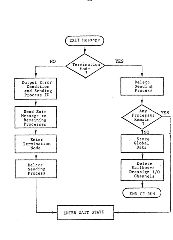
3-6 EXIT Message Processing Detail 80
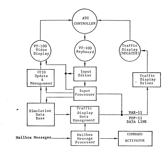
3-7 Functional Diagram of the ATM/C Controller Process 92
3-8 Traffic Display Layout 99
3-9 Controller Tabular Information Display Layout 105
4-1 Runway Scheduling Heuristic (Initialization Stage) 152
4-2 Runway Scheduling Heuristic (Feasibility and Optimization 157
Stages)
4-3 Final Vectoring Display 168
5-1 Typical Terminal Control Area Layout 176 5-2 Typical Nominal Approach Flight Plan 177
LIST OF FIGURES (continued)
Page
5-3 Example of an Approach Path Structure 182 5-4 Typical Flight Plan for the Base and Final Approach Phases 193
5-5 Horizontal Separations During the Final Approach Phase 197
5-6 The Kinematics of Aircraft Turns 208
5-7 Recovery from Early Speed Reduction in the Downwnind Phase 212
A-1 Minimum Interarrivai Separation (Overtaking Case) 225
A-2 Minimum Interarrival Separation (Opening Case) 225 B-1 The Kinematics of the Intercept Vector 230
LIST OF TABLES
Page
3-1 ATC Radar Beacon System Parameters 90
5-1 Effect of Aircraft Speed on Horizontal Separations and on the 202 Timing of Descent
A-1 Minimum Interarrival Separations at the Runway 226
CHAPTER 1
INTRODUCTION
1.1 Background and Motivation
Over the last twenty years advances in computer hardware have had a tremendous impact on every aspect of life. The civil air transportation industry, due to its close ties with the defense industry and the space program, has traditionally been among the frontrunners in the use of advanced computer technology. Today, computers play a crucial role in practically every aspect of air transportation. Starting from computer assisted design and manufacturing of aircraft and going all tne way to autopilots and automatic flight control systems, computers perform tasks of increasing number and complexity.
The Air Traffic Control (ATC) system in the United States has experienced ,the same impact. The effort towards air traffic control automation started over twenty years ago with the design and implementation of the current (third) generation Air Traffic Control system. TRACONs (Terminal Radar Control) and ARTCCs (Air Route Tratfic Control Centers) are the current ATC system's terminal area and enroute
facilities respectively. Together they provide a nationwide network of
computers which store, maintain, and distribute information on all IFR flights.
In the present ATC system, automation has been accomplisned in data collection and processing. Flight plan and surveillance data are automatically collected and distributed to appropriate stations. Radar returns are automatically correlated and filtered so that the controller has better position information than was previously available. Identity
and altitude information, supplied by beacon radar for suitably equipped
aircraft, is associated with radar returns. All the available data are used to generate clear alphanumeric traffic displays for the air traffic controller.
Generally, flight processing automation has improved the productivity of the air traffic controller by relieving him of many tasks which he had to perform manually up to then. In addition, it has enhanced the exchange of information among ATC facilities thus allowing better coordination. Finally, it has provided controllers with up to
date information on current and future flight plans and clearances for
IFR flights.
Further improvement of the current system's data processing
capabilities will be achieved through the Electronic Tabular Display
Subsystem (ETABS). The prototype software for ETABS is currently in its late stages of development under a Federal Aviation Administration (FAA) research and development program. ETABS will replace the "flight
strips" that are currently used by the controller. In addition it is designed to enhance inter-controller communication and provide more flexible data entry capabilities than are currently available.
It is generally accepted today that automation in data processing alone is not sufficient to provide the further improvements in the
capacity of the ATM/C system required by increasing traffic. This is particularly true in the terminal area which is usually the bottleneck
of the entire ATM/C system. Indeed the automation in data processing achieved to date has not provided any increase in the capacity of the facilities comprising the ATM/C system. Instead, it has decreased the controller's workload per aircraft handled so that today, in the terminal area ATM/C system at least, the human element is not the limiting factor determining the system's capacity. It follows tnat increases in the system's capacity will be achieved only through increased capacity of the airport and the ATC facilities up to the point when the capacity of these elements becomes comparable to that of the controller. Since it is very unlikely that physical expansion of the country's major airports will be feasible in the future, the increases in capacity have to be the result of more efficient use of available resources.
This realization has resulted in efforts to go beyond the data processing automation and design computer software which take part in decision-making for air traffic control. The most important of these efforts are reviewed in section 1.2.
(1) The recent air traffic controllers' strike and subsequent firing has
of course changed that situation but the effects are hoperully transient.
The work described here was motivated by the following premises which to some extent deviate from the prevailing trends in current research on the subject of ATC automation:
1. The high traffic density in the terminal area gives high
priority to the problems of automating ATC decision-making there. Once satisfactory solutions have been found for the terminal area airspace, the development of an automated system for the enroute airspace should be much simpler. In addition since the terminal area airspace is responsible for a large percentage of the delays
experienced in air transportation, any improvements in system operation that can be achieved through automation there will offer much larger benefits than those that can be achieved through automation of the enroute ATC system.
2. Decision automation should result in a true reduction of delays experienced by aircraft. Even though automated spacing of landing aircraft alone will result in some reduction of delays by avoiding excessive gaps between aircraft during the final approach phase, we believe optimal scheduling of all runway operations to have much greater potential for delay reduction and we therefore
consider it to be the primary ATC automation function. We propose, therefore, to view the problem not only as one or
traffic control but also one ot traffic management. In order to stress this view we will, hereafter, use Hsin's term Air Traffic- Management and Cantrol (ATM/C) system
instead of the more commonly used term "Air Tratfic Control". [HSI 76]
3. The proper man-machine relationship corresponds to timaster-slave"# with the human master accepting
responsibility for all decision making. He should be presented with recommendations by the machine, be able to obtain auxiliary information which supports the decision to satisfy himself that a correct recommendation has been generated, and most importantly be able to override that recommendation by requesting certain conditions to be met which will cause the machine to generate an alternative recommendation. Thus, we insist that the human controller play an active, dynamic role in decision making, and tnat no decisions are made without his explicit approval. We reject a passive, monitoring role for the human where he may somehow exercise a veto over machine decision making, and presumably intercede on an exception basis. Instead we see the human as the decision maker and the machine as
a "decision support" system which generates decision alternatives for him.
1.2 Overview of Previous Research
The topic of ATM/C automation has receivea much attention over the last two decades. A number of studies have been conducted and are continuing (see for example [ATH 71], [SAR 71],
[SCH
73)). We will not attempt to review all of them here but will restrict ourselves to themost important ones from the point of view of results as well as the impact they have had in shaping the cour.se of future work in the area.
Certainly the two most comprehensive studies in terminal area ATM/C automation have been the Metering and Spacing (M&S) program sponsored by the Federal Aviation Administration (FAA) and the development of the
Marine Air Traffic Control and Landing System (MATCALS) currently under
development by the US Marines.
The FAA's M&S program ([TAL 78), [TAL 80]) has its origins back in the early 60's. Its current version is the third of a series of field test programs. The first two, FASA (Final Approach Spacing for AXTS) and CAAS (Computer Aided Approach Spacing), suffered from a variety of problems (including procedural incompatibility, increased controller workload and in the case of CAAS the lack of a tracker) and thus yielded
(1) The term ATM/C automation will be from here on used to mean
automation of ATM/C decision support as contrasted with data processing automation which was discussed earlier.
few conclusive results. Computer simulations using the current version of the M&S system are being currently conducted at the NAFEC facility in Atlantic City.
The primary objective of the M&S system is to increase airport
landing capacity by providing more consistent inter-arrival spacing of landing aircraft than is now attainable, thus assuring an increase in runway utilization. The current M&S design does not provide for multiple airports or for multiple runway operations at the same airport.
Provision for departures is made only through use of normal gaps in the
landing stream as well as manually entered requests to lengthen tne landing interval by the controller. The landing sequence is determined based on the nominal time of arrival at the runway and resequencing of landings occurs only in cases where an aircraft cannot arrive at the runway or at one of the intermediate waypoints at the assigned time. Forward slippage and subsequent resequencing is also possible in the case of aircraft that are too early at one of their intermediate waypoints.
The current M&S effort marks the first time that an automated
flight plan generator has been accomplished. This has been a step in
the right direction, namely away from complex algoritnms based on
optimal control theory (e.g. [SAR 71] and
ESCH
73]) and towards simpler and faster path control techniques consistent with today's aircraft navigation capabilities. The objectives and scope of the M&S program has been limited due, apparently, to a decision by the FAA that someautomation system was needed quickly. Though this is certainly true, there is a need for longer term planning of a comprehensive terminal area ATM/C automation system which this work attempts to lay tne
foundations for.
By focusing on a quickly implementable system. the FAA M&S system
has incurred some serious drawbacks two of which have already been mentioned (handling of single runway configurations only, and the fact that departures are only implicitly taken into account). Another drawback in the current M&S work is the lack of conflict resolution. The flight plans generated for arriving aircraft are not checked for future violations of ATC separation standards. The human controller is required to provide altitude separation whenever flight plans for two aircraft are in conflict. A closely related issue is the system's lack of capability to recover and continue performing the required functions after controller intervention.
Finally, strict adherence to the first-come-first-served sequence in scheduling runway operations will unduly reduce the M&S system's efficiency. Optimizing the runway schedule based on the aircraft mix on hand, was considered but was not incorporated in the current M&S system
since
(1) The FAA has recently sponsored a study to determine the capacity
improvements that can be expected from optimal runway scheduling and revise the decision if satisfactory levels of improvement are found possible.
...the actual [capacity] improvement [from optimum scheduling] is expected to be less than 3% ... [and] can only be realized when system load is very high. But to achieve the improvement the sequence will appear abnormal
(compared to current ATC practices). The abnormal sequence will tend to increase controller workload (since the system's intent will be obscure) and, under heavy loads any increases in workload or any enigmatic system performance must be judged inappropriate.''
[TAL 78]
The 3% quoted in this paper is too low an estimate of the expected improvement in capacity. The work of Dear, [DEA 76], indicates that improvements in the 10 to 15 percent range are achievable. This relatively small capacity improvement can result in dramatic delay reductions when the airport is operating near saturation. It is true however that this improvement can be achieved only by implementing a flight planning algorithm which is flexible enough to accommodate frequent changes in the schedule of aircraft in their initial approach phase.
It is also not clear what is meant in the above statement with regard to the obscurity of the system's intent and the enigmatic system performance. There is nothing enigmatic about changing the sequence of operations in order to achieve better runway efficiency. In fact, final approach controllers today recognize the efficiency gained by sequencing aircraft of similar landing speeds in direct succession, and do it whenever it can be done easily. The optimization of runway schedule
The Marine Air Traffic Control And Landing System (MATCALS) is being implemented in response to operational requirements to upgrade and
automate the terminal air traffic control and all-weather landing control capabilities of Marine Air Traffic Control Squadrons (MATCS). It is intended to be a deployable system, designed to replace existing
MATCS equipment. The MATCALS concept will provide significantly improved capabilities through automation and advanced sensors, data links, displays and operator consoles.
MATCALS provides automated surveillance and traffic control throughout the airspace within 60 nautical miles of the airfield. In
addition it provides automatic and semi-automatic landing guidance and control under all weather conditions down to zero ceiling for suitably equipped aircraft.
MATCALS will be developed in three stages each with increasing
capabilities. The first stage will be completed in the early 80's and
its capabilities will be comparable to today's ARTS III system. The
second stage will include automatic traffic monitoring and hazard detection algorithms. The third and final stage will be a fully automated ATM/C system including such functions as runway scheduling and flight plan generation. The runway scheduling and flight plan generation algorithms described in this document will be the prototype software for the third stage of the MATCAL system.
The MATCALS effort should provide valuable new insight into the
problem of ATM/C automation and, even though it is concerned with
military operations, the MATCALS solutions and experience will be of great value in the development of an advanced automated ATM/C system for
civil aviation.
In parallel to the M&S system. the FAA is currently developing an automated ATC system for the En Route airspace. This system. called AERA (Automated En-Route Air Traffic Control), will centralize the
flight planning for the en route airspace. The concept of AERA is
defined in EGOL 81]. AERA will incorporate all the automation functions
that have thus far been developed by the FAA such as conflict alert,. em route metering. Automatic Traffic Advisory and Resolution Service
(ATARS), as well as state-of-the-art communications and display
technology such as the mode-S beacon provided by the Discrete Adaress
Beacon System (DABS), and the Electronic Tabular Display Subsystem
(ETABS). It will generate and maintain four dimensional conflict-free
flight plans for all IFR flights within the planning region. Aircraft characteristics such as true airspeed. optimal climb and descent profiles, etc. will be used to insure that projected flight plans are closely matched to the aircraft capabilities. In addition AERA will
provide routine aircraft separation and traffic flow control, as well as
clearance generation, delivery and acknowledgement functions.
The AERA concept will improve controller productivity by relieving controllers from many of the routine functions for which they are
currently responsible. In addition it will make more efficient use of
enroute airspace by limiting the need for procedural separation of
aircraft and by allowing freer movement of traffic capable of area
navigation. Finally AERA will coordinate the transition of traffic from
the enroute to the terminal area airspace and automatically perform flow control whenever necessary.
The AERA concept is an ambitious undertaking with a long term
planning horizon. It is our hope that the FAA will initiate a similar program to develop the terminal area ATC system for the year 2000 and
beyond.
1.3 Document Summary
The work described here is part of a continuing research effort at the MIT Flight Transportation Laboratory towards the development of prototype software for an automated terminal area ATM/C system. In
designing such a large scale software system, it is critically important
to clearly define its operation in terms of a number of functionally distinct but interacting elements. This breakdown is necessary in order to understand the ATM/C system at the conceptual level. Furthermore it is an essential step towards better organization of software into
functionally related entities (or modules). "Finally. by bringing out the interactions between various system modules it insures that the
operation of the overall system. The functional breakdown developed during the course of this research is presented in chapter 2.
The issue of compatibility among the functional specitications of various system modules is most apparent in the interactions between the man-machine interface and the automation software. Even though we realized at the outset that considerable research needed to be done before a successful design of the man-machine interface were achieved, we soon realized that the algorithmic development had to depend on the interactions with the air traffic controller. This means that human factors affect not only each module's function but also the algorithm used to perform that function. This realization led to the development
of a real-time interactive ATM/C simulation facility called TASIM. The
development effort for TASIM is presented in chapter 3.
TASIM is currently being modified, under a NASA/Ames contract, to
simulate both terminal area and enroute airspace. In addition to the
controller stations, it will include pseudo-pilot stations. The new software will provide the air traffic control environment for the Man-Vehicle Systems Research Facility (MVSRF) currently under development by NASA/Ames, [PAR 82]. In addition to the ATC subsystem
the MVSRF includes two cockpit simulators and will be used as a testbed
for research in cockpit as well as ATM/C automation.
In parallel with the development of TASIM, a real-time heuristic algorithm for automatic runway scheduling was designed and implemented.
The algorithm can handle multiple runway configurations. To date, however, it has only been successfully tested for single runway configurations. Chapter 4 discusses the problem of runway scheduling;
various alternative ways to formulate the problem are presented and
solution procedures are discussed; the algorithm which has been
implemented is described along with particular requirements that are
imposed on it by the nature of the system in which it will operate. This chapter also presents the concept for a final approach controller display which is designed to be used in connection with the automated runway scheduling function in order to allow precision delivery of landing aircraft at the runway in the absence of flight plan automation.
The final part of the research addressed the problem of automatic flight plan generation. The general approach has been that first, flight plans must be compatible with conventional navigation capability, and second, flexibility in path stretching and shortening must be preserved to the greatest extent possible at every point along the flight plan in order to provide maximum rescheduling flexibility. Accordingly, flight plans consist of a number of linear legs, and are generated based on a prespecified ground track structure. ThIs structure should be capable of providing a number of alternative paths at each intermediate point. One possible structure has been developed
and analyzed. Based on that we develop the methodology for the design
Chapter 6 summarizes the results and conclusions ot the work and identifies topics for further research and development.
CHAPTER 2
FUNCTIONAL DESCRIPTION OF AN AUTOMATED TERMINAL AREA ATM/C SYSTEM
2.1 Introduction
Any complex system can be described at various levels of aggregation. The system components at each level can themselves be complex systems requiring the same type of description. In this chapter the terminal area ATM/C system will be described and analyzed from this point of view. We will begin with the overall system and subdivide it into a number of components or subsystems. We next focus on the subsystem of primary interest in this research, namely the Ground Control system. Finally each of the elements of the Ground Control system will be broken down into functional modules and its operation will be discussed.
At each level we will focus not only on the function of each of the components but also on the interactions, the exchange of information that is required, as well as the flow of information from one component to the others as a result of specific external events (e.g. the ground control system response to a conformance alert). This chapter, therefore develops the framework for the design of the automated ATM/C
system and for the understanding, at a top level, of the requirements and the purpose of each of the automation functions. At the same time
it sets the basis for the organization and design of the automation software, since the functional modules in the final breakdown can be regarded as top level software modules for the ATM/C system.
2.2 The Generic Terminal Area ATM/C System
Air Traffic Management and Control (ATM/C) is a complex, interactive system that can be best modeled as a feedback control system. Its elements can be grouped into six generic subsystems:
Aircraft Control system (A/C)
Air-to-Air Data link system (AA COM) Automatic Ground Control system (AGCS) Ground-to-Air Data link system (GA COM)
Air-to-Ground Data Acquisition system (AG COM) Ground-to-Ground Data link system (GG COM)
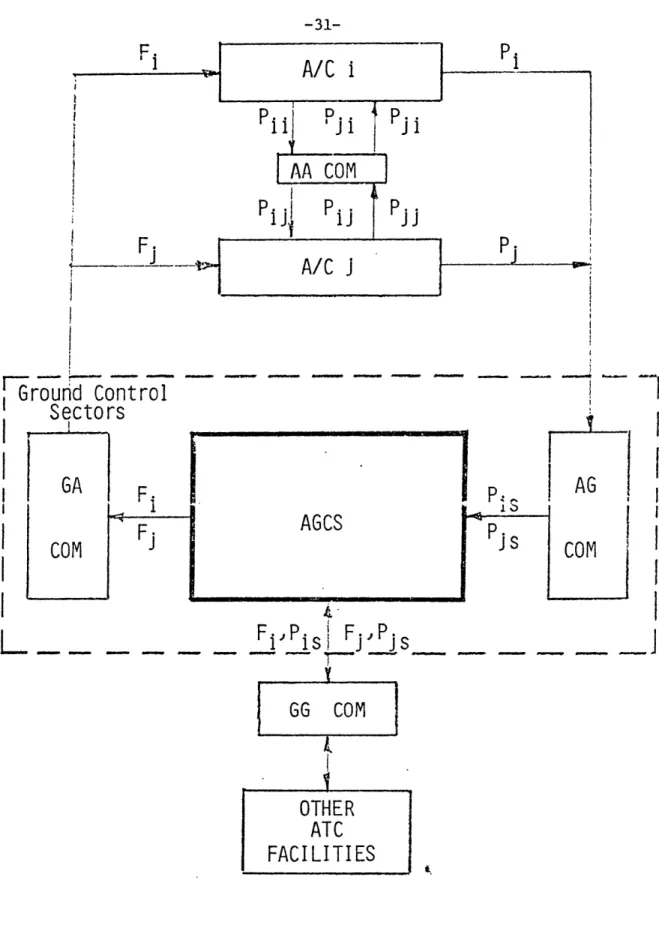
An overall block diagram of the terminal area ATM/C system is shown in figure 2-1. The major elements are the Automatic Ground Control
(AGCS) and the Aircraft Control (A/C) systems. While each of these are
feedback control systems themselves, they are elements of the major control loop for ATM/C. The Aircraft Control systems (or "targets")
output their "state" vectors, P.(t) and P.(t), which are measured by the
.1 J 4
Data Acquisition (AG COM) system to serve as primary dynamic input data
(1) The material in section 2.2 is drawn from the work of Hsin [HSI 76]
where the reader is referred for an excellent detailed discussion of advanced ATM/C systems.
Ground Control
Sectors
GA
GA
F
4 F.COM
J
I
IAG
j s
COM
4.GG COM
OTHER
ATC
FACILITIES
Figure 2-1. Overall Schematic Diagram for the Terminal Area
ATM/C System.
AGCS
to the AGCS. P.(t) includes information on the past positions of aircraft i. The AGCS processes this intormation and produces its output, F. and F., which are ATC commands or intended flight plans which
1J
describe the future path of the aircraft. These in turn are the primary dynamic inputs to the Aircraft Control systems. The various Data link systems accomplish the required flow of information.
The availability and distribution of information is of key importance in the operation ot the ATM/C system. It consists or the current "tstate", P.(t), and the "intended" future state or flight plans, F., of the aircraft targets in the system. P.(t) includes the aircraft
1. 1
position and altitude as well as aircraft velocity, accelerations, heading, bank angle, etc. The ATM/C information is not globally available. Aircraft heading, for example, is currently available only to the aircraft control system itself. Due to the variation in its completeness and because of measurement errors the aircraft state vector takes three distinct forms:
1. The actual aircraft state, P.(t)
2. The ground measured aircraft state, P is(), is estimated information on target i available to sector s of the Ground Control system, and includes the errors introduced
by the Air-to-Ground Data Acquisition system.
3. The airborne measured state, P.
.t),
is the aircraft state11
includes the errors introduced by the navigation and guidance subsystems of the A/C. Information on the state of other aircraft in the system can also be available to aircraft i, either in absolute form. P..
Ct)
or inJi.
relative form, AP. .(t). Absolute state vector inrormation may be relayed to other aircraft through the ground to air data link while relative information may be obtained by separation assurance systems onboard aircraft i.
The discrepancy between the ground measured and the airborne measured aircraft state information has far reaching consequences and requires some further elaboration. In addition to their defining difference, (i.e. their topological availability), they also differ in
their accuracy, timeliness, and completeness. Their difference in accuracy is obvious since they are measurements produced by two different systems. Also by virtue of the measurement systems involved, the airborne state information is generally instantaneous while ground measurements are made at relatively low sampling rates which depend on
the period of revolution of the radar antenna. Finally, while the airborne state information includes a wide variety of measured quantities. (e.g. position, altitude, airspeed, vertical speed. etc.)
(1) There exist, of course, military "tracking" radars which can directly control the direction of the beam thus producing very high sampling rates for particular targets. These radars measure the aircraft position with much better accuracy than conventional radars. It is very unlikely. however, that these will be used for civil air traffic control in the foreseeable future.
today's surveillance systems measure only range and bearing and can receive encoded identity and altitude information from mode-C
transponders. Generally therefore, the airborne information on the
aircraft state is more complete and in many cases more accurate than the
intormation available to the ground.
The issues of accuracy and availability of aircraft state
information are important since these are factors which determine the
efficiency and the feasibility of the automated ATM/C system. Sophisticated automation in ATM/C cannot be achieved without high
quality surveillance and tracking data.. These issues will be discussed
again in connection with automated flight plan generation and conformance monitoring.
We can now show the elements within the block for the AGCS shown in figure 2-1. As depicted in figure 2-2, the AGCS has three major
functional elements: the Flight Plan Generator (FPG), the Traffic Monitor (ATM). and the Command Processor (ACP).
The FPG is responsible for creating decisions regarding the flow of traffic in the terminal area ATM/C system. It is best described in terms of an optimization process. The state of all controllea aircraft is the input variable of the process. Thegoutput will be the ATC commands which define a flight plan , F., for each controlled aircraft, i. The ATM/C rules and regulations, and the aircraft's dynamic
ATM/C DISPLAYS
(TD and CTID)
The Major Elements of the AGCS.
ATM/C
TRAFFIC
MONITOR
(ATM)
ATM/C
COMMAND
PROCESSOR
(ACP)
Ps
. S
ATM/C
FLIGHT PLAN
GENERATOR
(FPG)
-Conflict Checking
Figure 2-2.characteristics (e.g. minimum and maximum airspeeds, etc.) are constraints which determine the set of feasible ground control decisions. Finally, the ATM/C strategy defines the objective function which the FPG is to optimize.
The Traffic Monitor naturally divides into two sub-elements: the
Conformance monitor and the Hazard Monitor.
The Conformance Monitor, consisting of the Conformance Detection
(CD) and the Conformance Resolution Path Generation (CRPG) functions, is-preventive in nature; it monitors aircraft adherence to the ground
control decision and generates a conformance alert when deviations from the established flight plans exceed prespecified conformance limits.I The Hazard Monitor, consisting of the Hazard Detection (RD) and the Hazard Resolution Path Generation (HRPG) functions, is responsible for enforcement of the ATM/C satety rules; it generates a hazard alert
whenever violation of ATM/C standards is imminent. A distinction should
be drawn between the Hazard Monitor and the conflict check. "Hazard" implies a perilous current situation in terms of the actual positions of
aircraft, whereas "tconflict" refers to a possible future situation based on flight plans. In particular, a flight plan is in conflict with another if an aircraft adhering to it within the conformance limits wiil
create a hazard (i.e. violate the ATM/C rules) at some future point in
(1) The conformance limits depend primarily on the FPG logic, but the
accuracy of the surveillance and the onboard navigation equipment is also a factor.
time. Accordingly the conflict check is an integral part of the FPG and appears in figure 2-2 to indicate that flight plans generated are conflict-free.
The Command Processor also subdivides into two sub-elements: the Command Generator (CG) and the Command Activator (CA). The Command
Generator uses flight plan data to determine for each aircraft a set of commands and associated times of initiation, such that if the commands are followed, the aircraft will remain in conformance to its flight
plan. The same flight plan may conceivably produce different commands
for different aircraft since the aircraft navigation capabilities
determine what type of commands the pilot can be expected to accept. The Command Activator is responsible for the timely dispatch of commands
to the air traffic controller and (if digital data link is available) to the aircraft.
The only manual activity depicted in figure 2-2 is that of the
human controller who controls the overall system performance through
real time inputs to the Traffic Display (TD) and the Controller Tabular
Information Display (CTID) software. All other elements can have the
form of computer algorithms which can operate automatically providing
decision support within the framework established by the ATM/C controller. He remains the commander responsible for the system's
Before we discuss the various automation functions in more detail,
the following definitions will be useful in describing flight plans. A
point W in 3-dimensional space will be callea a waypoint. We shall
define tim-point. W(t), as four dimensional waypoints for which the
time dimension is also specified. A flight plan for aircraft i. F., is
3.
a set ot waypoints or time-points detining a path in 3 or 4-dimensional space. We limit our definition of a terminal area flight plan to include only time-points whose time coordinate lies in some interval
(t t f). Unless stated otherwise, the interval of interest will be the time during which the aircraft is under the control of the terminal area
ATM/C controller. For a landing aircraft i, this would be from the time
it is handed off to the ATM/C controller to the scheduled time of arrival at the assigned runway n (STAR ). For departing aircraft the
interval of interest is from the scheduled time of arrival at the
runway, i.e. the takeoff time, until the scheduled time of arrival at the exit fix (SXT.). F. is feasible if it is consistent with the
2. i
aircraft's performance characteristics (such as airspeed, climb and descent rates, taxi speeds, etc.).
2.3 The ATM/C Flight Plan Generator
In this section the FPG is described in more detail with particular emphasis on the interactions between the various automation functions that are identified. In figure 2-3 the FPG is shown as consisting ot three distinct functions:
COMMAND ACTIVATOR
(CA)
COMMAND
GENERATOR(CG)
L
f.azard7
F. AvoidancI
R
G L-Commandsj
i
Pjs
D r CONFORMANCE ION DETECTION)
j
2
(CD)
D CONFORMANCE ION RESOLUTION PATH ION GENERATION(CRPG)
Flight Plan i[Re-acquisition Commands
- -- - - -
-FI
Res TRAFFIC FLIGHT PLAN GENERATOR(TFPG)
-Conflict Checkingcheduling
RUNWAY SCHEDULER(R
S)
4-ATM/C DISPLAYS
(TD
and
CTID)
NOMINAL
I
FLIGHT PLAN
1P.
is GENERATOR(NFPG)
IJ
P.s Pis.%7
'js
Functional Block Diagram of the AGCS.
I
1. Nominal Flight Plan Generator (NFPG)
2. Runway Scheduler (RS)
3. Traffic Flight Plan Generator (TFPG)
2.3.1 Nominal Flight Plan Generator
Given the present position, destination, and aircraft performance characteristics, the NFPG determines an efficient flight plan. F , that would be assigned to an aircraft in the absence of any other traffic. The flight plan assignment assumes nominal performance characteristics (terminal area speed, descent or climb rates etc.) depending on the
aircraft type. Where applicable, standard deparrure and arrival routes could be used for this purpose. The nominal flight plan establisnes earliest times of arrival at various points in the terminal area or at the airport. Of particular interest is the earliest (preferred) time of arrival at the runway threshold (PTAR)1 which establishes the nominal (first-come-first-served) sequence of operations (NSAR). NSAR is the
basis for the sequencing constraints which will be introduced in section
2.3.2
The NFPG is invoked whenever new aircraft enter the system (either
for takeoff or for landing) or when the ATM/C controller requests a schedule change (e.g. in the case of a missed approach).
(1) The term "time of arrival at the runway" is used for both landings
and departures. For landings it is the time the aircraft crosses the runway threshold, while for departures it corresponds to the time the takeoff roll starts.
2.3.2 Runway Scheduler
Given a runway system consisting of Nr runways, and Na aircraft, we define a runway schedule S as the set of STAR. 's (scheduled times of
in
arrival at the runways) for all aircraft i and runways n in the system.
- S
=
{
STAR. in , i=1,2,3,...,N ar n=1,2,3,...,N }Adoption of a specific runway schedule will be referred to as a scheduling decision. Note that a scheduling decision includes the assignment of runways to aircraft whenever more that one runway is active. If runway n is assigned to aircraft i, STAR. has no meaning for all m other than n. By convention we set STAR. to zero if runway m is not the assigned runway for aircraft i. When two or more runways are active, we may restrict landing and/or takeoff operations to certain runways, perhaps depending on the type of aircraft.
The runway schedule defines the efficiency of the terminal area
ATM/C system (i.e. the time interval between successive operations).
Generating the schedule thus represents the major optimization effort in the AGCS decision process. Unlike today's manual system wnere ATM/C objectives and strategies employed to achieve them are only defined in
implicit and qualitative terms, the objectives,, performance criteria to
be optimized, and strategies which are implemented in the automatic system are well defined functions of the STAR's. For example, the
and the strategy adopted will be a specific runway schedule which accomplishes that. In chapter 4 we discuss in detail alternative performance criteria, their mathematical representation and their effects on runway scheduling algorithms.
The Runway Scheduler is a computer algorithm which solves a well defined optimization problem: Given the nominal sequence at the runways
(NSAR), and for each aircraft in the system:
1. its performance characteristics,
2. its Earliest Feasible Time of Arrival, EFTAR. , at each in
active runway n, and
3. its Latest Feasible Time of ArrivaL, LFTAR. , at each in
. 1
active runway n
find a particular schedule S which optimizes the performance criterion and satisfies the following constraints:
1. Spacing: the minimum required time separations between all pairs of operations i and
j
are not violated;(1) EFTAR. and LFTAR. will depend on the approach routes and the
in in
flight planning logic. They will be discussed further in chapters 4 and 5.
2. Sequencing: no aircraft is shifted by more than a prespecified number of positions from its position in the nominal sequence;
3. Scheduling: the scheduled time of arrival at the runway
for all landing aircraft should be within the feasible time interval, i.e., for all landing aircraft i assigned to runway n,
EFTAR. <STAR. < LFTAR.
in in in
4. Ldie: The current scheduled time of arrival at the
runway cannot change if it is within the prespecified lead time from the current clock time;
Lead time constraints are designed to avoid last minute changes in the schedule. For departing aircraft they allow for taxiing time and
smooth operation of the takeoff queue ne-ar the runway threshold. These
constraints also provide pilots of landing aircraft enough advanced notice of their exact landing time so that adequate preparations for landing can be made. Under normal conditions the STAR for each aircraft
stabilizes as its scheduled time approaches. The lead time constraint
absolutely ensures that this will always happen at some prespecified time interval before STAR.
2.3.3 Traffic Flight Plan Generator
*
Given the new runway schedule S , the current positions, and the performance characteristics of all the aircraft in the terminal area
ATM/C system, the TFPG completes the ground control decision process by
generating a new Flight Plan Decision,
* *
(
(t)
{
F. , i=1, 2,3 ,...,N }i.e. 4-dimensional flight plans F., such that:
1. F. is feasible for aircraft i, i=1.2,...,N
3. a
2. minimum airborne separations are satisfied throughout, i.e. the flight plans are conflict-free.
*
3. a smooth transition between F. and F. is provided for
all i=1,2,...,N a
4. The pilot workload from the time of system entry to the time of system exit is kept within reasonable limits.
The flight plans generated here are called traffic flight plans since conflicting traffic is taken into account by the second of the above constraints.
The TFPG is normally invoked after a new scheduling decision has been made due to a new aircraft entering the system or due to a missed approach. It may also be invoked however due to a conformance alert.
There is a possibility that a set of conflict free flight plans cannot be found. In this case the TFPG will invoke the runway scheduler requesting a schedule modification.
2.4 ATM/C Command Processor
This function consists of two sub-functions, the Command Generator
(CG) and the Command Activator (CA).
The Command Generator uses flight plan data to generate a set of commands which, if followed, will guide the aircraft along its assigned flight plan. The commands take the form of alphanumeric messages in terminology commonly used today for voice communications. For a
specific flight plan the actual commands generated depend on
Ci)
the aircraft's navigational capability, and (ii) the prevailing winds. Theaircraft's navigational capability is either be conventional (i.e.,
VOR/DME or TACAN navigation) or advanced (i.e., 3D or 4D Area
Navigation). For conventionally equipped aircraft the set of allowable commands is of the "radar vectoring" type whicg specify heading, speed
and altitude. Aircraft equipped with 3D or 4D Area Navigation (RNAV), can be commanded to track directly to the next waypoint or time-point.
In order to achieve good conformance to 4-dimensional flight plans,
speeds and headings should be corrected to account for the estimated
winds in the vicinity of the aircraft. Occasionally a segment of a flight plan will coincide with a VOR radial, particularly in the early stages of arrival routes for landing aircraft, and the late stages of departure routes for takeoffs. In that case a command to track a VOR radial would be preferable to a heading command since compensation for wind is performed by the pilot (or autopilot) in tracking. Similarly, RNAV commands will be preferable to heading commands and will be used
whenever possible.
Each command message includes at least four additional pieces of information necessary to its further processing:
1. the identity of the aircraft to which the message is directed
2. the time of issuance to the ATM/C controller
3. the time of transmission to the aircraft
4. the acknowledgement of the command by the aircraft
The difference between issuance and transmission time will be such as to give the ATM/C controller the opportunity to study and (if deemed necessary) modify the command, to validate its automatic transmission to
the aircraft at the correct time if digital data link is used for ground to air communications, and to prepare for voice transmission otherwise.
The Command Activator is responsible for the timely dispatching of command messages. The presentation of commands to the ATM/C controller can be achieved in three stages. First, the controller will be able to review all future commands for any or all aircraft under his control. This list of commands can be displayed in the CTID and is updated when flight plans change. The controller may also modify any command at this stage. When the command issuance time has been reached, the command will be moved to the issuance area which may be in the traffic display for easier reference. Additional methods to attract the controller's attention to it (e.g. blinking) may be used. Finally after the transmission to the aircraft has been initiated, the command is moved to a post view area. Thus the controller is reminded of the "active" commands for all aircraft under his control. In this area, the commands may also be flagged when acknowledged by the aircraft crew.
The transmission to the aircraft is initiated when the controller validates the command. Since it can be assumed that the AGCS will be
capable of both voice and data link (mode-S) communications, the processing of the validated command by the Command Activator will depend
on the aircraft communication capabilities.
The important issue in this respect is that the controller should not be responsible for determining the transmission method. This means
that the Command Activator will determine if the target aircraft has
mode-S capability. If so. the command will be moved to the postview
area. If not, the command will remain in the issuance area and the controller will realize that he has to transmit the command through voice communication. An interesting option in this regard is the
possibility of using voice synthesizers to alleviate the controller
workload associated with routine transmission of commands via voice communications. The computer may be able to automatically synthesize and transmit voice commands to all aircraft that do not have mode-S capability.1
If validation is not made by the specified time of transmission to the aircraft, the Command Activator dispatches an appropriate alert message to the ATM/C controller and no action is taken until the ATM/C
controller validates the clearance or initiates another command for the
aircraft to follow. Similar processing takes place after the command is transmitted to the aircraft. If a specified time interval has elapsed without acknowledgement of the command by the pilot, appropriate
messages are automatically dispatched to the pilot and to the ATM/C
controller.
(1) Voice synthesis has tremendous potential in many aspects of ATM/C automation. The technology, however, is still in its infancy and a lot of research is still required with regard to the technological as well as to the human factors aspect before its usefulness can be assessed.
2.5 The ATM/C Traffic Monitor
2.5.1 Conformance Detection and Resolution
This is the primary mode of automatic monitoring for the AGCS.
Deviations between the indicated surveillance position of the aircraft
and the desired position according to its currently assigned flight plan are monitored. When deviations exceed externally established limits (which may depend on the geographic location of the aircraft with respect to the assigned runway) the aircraft is declared out of
conformance with its flight plan and a conformance alert is generated.
This will generally cause the TFPG to be invoked.
In some cases it will be reasonable to quickly bring the aircraft back into conformance through immediate "correction" vectoring. This function is performed independent of the TFPG by the Conformance Resolution Path Generator (CRPG). This type of recovery from a
conformance alert will be desirable when lateral deviations from the flight plan are detected. Longitudinal deviations, on the other hand, will most likely be the result of discrepancies between the aircraft's airspeed and the nominal airspeed assumed for the purposes of flight
planning. In addition to the fact that no aircraft can be expected to
fly at exactly its nominal airspeed, such disagepancies will occur due
to erroneous estimate of the wind speed and direction particularly after a change in heading. In that case, it will generally be preferable to
modify the flight plan for the aircraft based on the new information (namely the new estimate of the ground speed) available to the TFPG.
2.5.2 Hazard Detection
Hazard Detection is a backup to the primary mode of providing separation assurance, namely through generation of conflict-free flight plans and conformance monitoring. Controlled aircraft must be out of conformance before they can be in hazard.
Traditionally, this function monitors the snort term straight line projections (typically of the order of 30 seconds) of aircraft
separation from ground terrain as well as the projections of the
positions of other aircraft in the system. We will call this the
"unassuming" mode (U-mode). This approach has not been very successful, particularly in the terminal area where the proximity of aircraft
results in high false alarm rate.
In an automated ATM/C system, flight plan information may be provided to the Hazard Detection function in order to reduce the false
alarm rate. We will call this method the "informed" mode (I-mode).
There is a certain danger to the I-mode since the Hazard Detection
function is primarily responsible for safeguarding against "blunders"
either by the air traffic controller or the pilot. The I-mode is not particularly suited to detect such blunders because its assessment of
aircraft should be doing. It is possible, however, to maintain the same
level of performance with respect to blunders and at the same time to
increase the reliability of the Hazard Detection function by having both modes operating in parallel.
We can have two levels of hazard alert. The first level is declared when the U-mode declares a hazard but the I-mode determines that it will be resolved according to flight plan inrormation. For example, one of the two aircraft involved is due to initiate a 90 degree turn in the next few seconds. In this case the controller may be warned in order to insure that the expected command is actually in the process of being initiated. No further action is taken unless explicitly requested by the air traffic controller. The second level will be declared when both the U-mode and the I-mode declare a hazard, or when the (internally determined) probability of an actual blunder has reaced a specified threshold value (for example, the time that the command in question is to be initiated has been reached). In this case, in addition to the hazard message to the air traffic controller, conformance monitoring for the aircraft will be suspended, and the
Hazard Resolution Path Generator will be invoked in order to generate
hazard resolution commands. Note that the conformance detection function should be declaring a conformance alert and trying to solve the problem at the same time.
(1) This will generally not be possible if the conflict checking
A hazard alert status is maintained for the aircraft until it is
found not to be in hazard any more. At this time the hazard alert is removed. If there had been a second level alert, conformance monitoring is resumed. Presumably the hazard avoidance path will have placed the aircraft out of conformance with its original flight plan. A normal conformance alert to will then be generated causing the CRPG or the TFPG to be invoked in order to solve the problem of returning the A1'M/C system in its primary monitoring mode.
2.5.3 Hazard Resolution Path Generator
This function is invoked whenever a second level hazard alert occurs. Two modes of operation are possible depending on the type of ground-to-air communication available.
If voice communication is employed, a recommended avoidance path will be generated and made available to the Command Generator for processing and immediate transmission to the ATM/C controller. The controller then chooses to validate the recommended solution or generate
his own. In this mode it may be advantageous to provide the ATM/C
controller with more than one alternative.
If a digital ground-to-air data link is available, it may be feasible to generate a single avoidance path and, request immediate processing by the Command Generator and transmission to the aircraft.