HAL Id: hal-00089703
https://hal-insu.archives-ouvertes.fr/hal-00089703
Submitted on 24 Aug 2006
HAL is a multi-disciplinary open access archive for the deposit and dissemination of sci-entific research documents, whether they are pub-lished or not. The documents may come from teaching and research institutions in France or abroad, or from public or private research centers.
L’archive ouverte pluridisciplinaire HAL, est destinée au dépôt et à la diffusion de documents scientifiques de niveau recherche, publiés ou non, émanant des établissements d’enseignement et de recherche français ou étrangers, des laboratoires publics ou privés.
Effect of shape and orientation on rigid particle rotation
and matrix deformation in simple shear flow
Laurent Arbaret, Neil S. Mancktelow, Jean-Pierre Burg
To cite this version:
Laurent Arbaret, Neil S. Mancktelow, Jean-Pierre Burg. Effect of shape and orientation on rigid particle rotation and matrix deformation in simple shear flow. Journal of Structural Geology, Elsevier, 2001, 23, pp.1, 113-125. �10.1016/S0191-8141(00)00067-5�. �hal-00089703�
Effect of shape and orientation on rigid particle rotation
and matrix deformation in simple shear flow
Laurent Arbaret, Neil S. Mancktelow and Jean-Pierre Burg
Geologisches Institut, ETH-Zentrum, CH-8092 Zürich, Switzerland
Abstract
The rotation behaviour of rigid particles from a wide range of symmetry classes was analysed in a series of three-dimensional analogue experiments, in which the particles were embedded in a transparent linear–viscous matrix deformed to large shear strains. Comparison of the measured trajectories with theoretical periodic paths for rigid ellipsoids shows that quadratic, slightly orthorhombic and monoclinic particles have trajectory paths and rotation rates closest to theory. Orthorhombic and monoclinic particles, with a minimum aspect ratio >1.5, develop non-periodic trajectories. The results establish that the simplified theoretical model for ellipsoidal forms is a good approximation for a wide range of natural particle shapes. The relationship between the rotation of a rigid particle and deformation of the adjacent matrix was also determined in a series of experiments by placing the particle at different depths relative to an imprinted grid. The results are well illustrated by the surface passing through the centre of the particle and initially parallel to the shear plane. Two deformed regions in the matrix are recognised. In the first region, the matrix rotates with the particle, together forming an approximately ellipsoidal object. The second region is dominated by folds, of limited extent along the rotation axis and greatest extent in a direction that rotates asymptotically toward the shear direction. The folds rotate more slowly than the principal direction of maximum finite stretch.
1. Introduction
Kinematic analyses of non-coaxial deformation in strongly deformed rocks and magmas often rely on the observed geometry of rigid particle systems. Two complementary approaches are used: (1) shape-preferred orientation analysis of inclusions, applying the model for rotation of rigid ellipsoids embedded in a Newtonian matrix (e.g. Willis, 1977; Fernandez et al., 1983); and (2) the extent and symmetry of rolling-structures developed in the matrix around the rotating rigid particle (e.g. Van den Driessche and Brun, 1987; Passchier and Simpson, 1986).
Equations for rotation of an ellipsoidal particle in a simple shear regime are derived from the analytical solutions of Jeffery (1922). These equations give the three-dimensional trajectory and angular velocity of the long axis of a particle as a function of its aspect ratio and the applied shear strain. The experimental work of Willis (1977), who considered the particular case of orthorhombic objects with a fixed axis of rotation, has demonstrated that the Jeffery model (1922) can be extended to more generally shaped bodies. Similarly, the experiments in simple shear flow of Fernandez et al. (1983) have shown that the theoretical model is also a good approximation for two-dimensional rectangular particles (i.e. particles disposed at the free surface of a Newtonian matrix). However, natural particles commonly have a three-dimensional geometry that is significantly different from an ideal ellipsoid. In particular, for the common case of single-crystal porphyroclasts, this depends both on the crystallographic system of the mineral and on their anisotropic growth during crystallisation. Numerical
iterative simulations show that such triaxial ellipsoidal particles may follow complex movement paths ( Freeman, 1985) and develop irregularly oscillating fabrics of particle populations ( Je ek et al., 1994).
During rotation of a rigid particle, perturbation in the flow field of the surrounding matrix produces asymmetric rolling-structures with an intrafolial fold geometry around the particle (Van den Driessche and Brun, 1987). The monoclinic symmetry of these perturbations reflects the non-coaxial nature of the deformation and is a useful sense-of-shear criterion in intensively sheared rocks ( Passchier and Simpson, 1986; Hanmer and Passchier, 1991; Passchier, 1998). The evolution and geometry of these structures in two dimensions were investigated in the analogue experiments of Van den Driessche and Brun (1987), using a rigid and rectangular particle rotating on the free surface of a matrix submitted to large simple shear strains. They found that rolling structures develop passive isoclinal folds parallel to the principal finite strain direction λ1 in the vicinity of the particle. Bjørnerud (1989) obtained
similar features and reached the same conclusion using a two-dimensional numerical simulation of flow around a rigid inclusion of circular cross section. However, the influence of the velocity perturbation in the third direction, i.e. the direction perpendicular to the direction of shear in the plane of undisturbed flow, was not investigated in these experiments. In sheared rocks, localised fold structures without an associated visible particle are common. They are generally assumed to be associated with an obscured object, which is not in the plane of observation ( Bjørnerud, 1989).
This study presents observations from three-dimensional analogue experiments that investigate the rotation behaviour of variously shaped particles during progressive non-coaxial deformation, approaching simple shear. The existing theories are first summarised. The flow field in the ring-shear machine employed is characterised and compared to theory. Results from the three-dimensional experiments for trajectories and rotation rates of different classes of particle shapes and initial orientations are then presented and discussed, as well as the relationships between rotation of rigid particles and the perturbed flow field of the adjacent passive matrix. Comparison of the results with the simplified mathematical model for axisymmetric ellipsoidal particles demonstrates that the analytical solutions of Jeffery (1922) are applicable to a wide range of different symmetry classes of particles.
2. Theory
The three-dimensional path of an axisymmetric particle in a Newtonian linear–viscous matrix undergoing homogeneous simple shear is given by the analytical solutions of the Jeffery’s equations (Jeffery, 1922; Reed and Tryggvason, 1974; Willis, 1977):
where ς=a/c is the aspect ratio of the particle, with a the long axis and c the short axis. The angles (φ, φ') and (θ, θ') represent the azimuth and plunge of the long axis relative to the plane of undisturbed flow measured before and after the incremental shear strain γ.
From these equations, the two-dimensional analytical solution describing the rotation path of a particle located in the plane perpendicular to the rotation axis can be derived as (Gay, 1968; Fernandez et al., 1983):
where α and α' are the orientation of the long axis a of the particle before and after the incremental shear strain γ and the shape factor K is given by (Willis, 1977)
(1), (2) and (3) imply that the motion of an axisymmetric particle is cyclic, with a period depending on its aspect ratio. The instantaneous angular velocity is always at a minimum when the long axis of the particle is parallel to the shear direction.
3. Material and methods
3.1. Apparatus
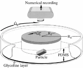
The ring-shear apparatus used to conduct the high-strain simple shear experiments consists of two concentric cylinders (Fig. 1), which rotate with the same angular velocity but in opposite directions. The concept of the system is similar to the apparatus of Passchier and Sokoutis (1993) and also has similarities to that used in the two-dimensional experiments of ten Brink and Passchier (1995). The outer cylinder is transparent to allow measurement of the vertical position of objects. The bottom is covered with a 1-cm-thick layer of low-viscosity glycerine acting as a lubricant. The matrix material is a transparent polydimethyl-siloxane polymer (PDMS SGM36) manufactured by Dow Corning (USA). The PDMS closely approximates Newtonian behaviour with a viscosity of ca. 5×10⁴ Pa s for shear strain rates of less than 9×10⁻⁴ s−1 (Weijermars, 1986; Passchier and Sokoutis, 1993), which is always the case in the
Fig. 1. Sketch of the experimental setup. The three-dimensional particle is embedded in transparent silicone PDMS placed between the two counter-rotating cylinders. Re=300 mm and Ri=180 mm are the radii of the
external and internal boundaries subjected to angular velocities of = − respectively. During an experiment, colour slides are taken using a mounted 35-mm camera with its focal plane oriented parallel to the free surface of the silicone.
In the apparatus, the simple shear strain is not constant but depends on the radial distance between the particle and the rotation axis of the ring (Reiner, 1960). The viscous resistance is controlled by the shear strain rate , which is given by (Masuda et al., 1995):
where Re and Ri are the radii and and the angular velocities of the external and internal
boundaries respectively (Fig. 1).
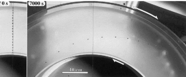
The evolution of the shear gradient in the apparatus was controlled experimentally for direct comparison with Eq. (5). Small spherical grains of paraffin were regularly distributed on the surface of the PDMS along a line initially perpendicular to the shear direction ( Fig. 2, 0 s). For each step of 1400 s, the angle between the initial and final positions of each grain was measured on digitised images. This was then compared to the angle calculated from the angular velocity as a function of the radial distance r, which according to Reiner (1960) and Masuda et al. (1995) should follow the theoretical relationship
Fig. 2. Evolution of the shear gradient in the ring-shear machine as marked by small spherical grains of paraffin, placed on the surface of the PDMS along a line initially perpendicular to the shear direction (0 s), and after 7000 s.
The results, reported in Fig. 3, show a very good fit between theory and observation. The greatest departure is observed close to the inner cylinder, where the markers’ rotation is slower by 11% than the predicted rotation. This minor divergence between measurement and theory is possibly due to two factors: (1) optical distortion in the recording photographs caused by the small focal distance (50 cm) between the camera and the PDMS surface; and (2) weak non-linear viscous effects in the matrix with increasing shear strain rate toward the inner cylinder. However, in general the experiment confirms that the shear strain depends on the measurement position between the cylinders in a manner very closely approximated by Eq. (5). The strain applied to particles in the following experiments was therefore calculated from Eq. (5), using the rotation angle of the cylinders, the time step and the position of the particle centre between the cylinders.
Fig. 3. Comparison between the displacement of rigid markers placed on the surface of the silicone at various distances r from the centre of rotation and the theoretical curves given by the equation of Reiner (1960; continuous curves) for measurements at five time steps (in seconds).
3.2. Material
The particles are rigid blocks of polyethylene (PEHD 500). The density of this material is 0.91, which is very close to that of PDMS (0.97), and vertical displacement of the particles
during experiments is therefore small (<4 mm for experiment duration of 5 h). Three different symmetry classes of particles were used (Table 1). The first class is composed of quadratic particles with planar (long axis a=intermediate axis b) or acicular (intermediate axis b=short axis c) shapes. The second class corresponds to orthorhombic particles characterised by three perpendicular axes of unequal length. The third class comprises three monoclinic particles with two axes not perpendicular (see Table 1). The length of axes is accurate to±0.25 mm. To allow three-dimensional measurements as outlined below, opposite faces are coloured red (major faces [ab]), green (intermediate faces [ac]) and blue (minor faces [bc]).
Table 1. Geometrical properties of the particles used in the experiments. a is the long axis, b the intermediate axis and c the short axis. Length (mm)
3.3. Experimental procedure and measurements
Particles were placed manually in the PDMS as close as possible to the spatial midpoint between the two cylinders. Before starting deformation, the system was left stationary for ca. 12 h to allow closure of the space above the particle by flow of the silicone. Because the particle may move laterally by a few millimetres from its initial position during this stage, the value of r used in evaluating Eq. (4) varies slightly. Consequently, the shear strain γ at a particular step and the final shear strain γmax are not necessarily the same in all experiments,
although the time step for measurement and rotation rate were fixed.
Experiments were performed at a room temperature of about 22°C and a shear strain rate varying from 1.36×10⁻³ s−1 at the inner cylinder to 4.91×10⁻⁴ s−1 at the outer cylinder, with a value of 7.67×10⁻⁴ s−1 in the central region of interest (see Fig. 3 and Eq. (5)). Colour slides were taken at regular time steps using a 35 mm camera placed vertically, i.e. parallel to the XZ plane of the fixed reference frame, which correspond also to the free surface of the PDMS
(Fig. 1 and Fig. 4). The colour slides were subsequently digitised with an image resolution of 3072*2048 pixels. Reflections of the particle surface colours were removed and borders partially masked by residual bubbles in the PDMS were corrected.
Fig. 4. Definition of the reference frames as used in the text. XYZ is the external fixed reference frame with XY the plane of (undisturbed) shear flow and X the direction of shear. λ1, λ2, λ3 are directions of the principal finite
strain axes with λ2 parallel to the rotation axis. a, b and c are vectors parallel to the principal axes of the
orthorhombic particle with a length of a , b and c respectively.
Orientation measurements of particle axes are based on the orthorhombic property that the line of intersection between two differently coloured planes must be perpendicular to the third plane (Fig. 4). A personal computer program performs the necessary calculations. In the general case of three visible faces, the program detects each visible border and the triple point formed by their junction to determine their orientation ( Fig. 5). The plunge is calculated from the length measured on the image compared with the known true length of the border. The calculation is performed automatically for all scanned colour slides and the results are plotted on an equal area stereographic projection. The results are then compared to the theoretical angular velocity Tv and trajectory Tt of ellipsoids calculated using Eq. (1) and Eq. (2) for the
known aspect ratios a/c and a/b of the particle. Different sets of experiments were performed for particles with different shape properties (Table 1) and different initial orientations with respect to the fixed reference frame ( Fig. 4).
Fig. 5. Procedure for calculation, using digitised images, 3072×2048 pixels in size, of the orientation of the three major axes, which characterises the particle. The results are plotted on a lower hemisphere, equal area stereographic projection.
4. 3D rotation of rigid particles
Three sets of experiments were performed to study the trajectories and rotation rates of axes of differently oriented quadratic, orthorhombic and monoclinic particles. The fourth set considers the particular case in which one axis of the particle is parallel to the rotation axis λ2.
4.1. Quadratic particles
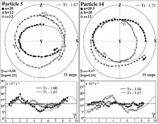
In this first set of experiments, the acicular particle 5 and the planar particle 14 were used (Fig. 6). The trajectory path of their long axis a is consistent with the theoretical trajectory Tt
of an ellipsoid having an aspect ratio of 1.67, which corresponds to the aspect ratio a/c of both particles. For the planar particle 14, axes a and b were supposed to be equal within the limits of manufacture. However, during the experiment, the a axis acted as the long axis controlling the particle rotation. Accurate post-experiment measurement revealed that axis a was actually 0.5 mm longer than axis b. This observation indicates that a very small difference in length (in this case ca. 2%) can markedly influence the rotation path of the axes. Excellent correspondence between experiment and theory is also obtained for the angular velocities. The symmetry axis a of the acicular particle 5 has an angular velocity history close to that calculated for a theoretical ellipsoidal particle with the same aspect ratio (Tv−1.67, Fig. 6).
The same angular velocity history is observed for the symmetry axis (short axis c) of the planar particle 14. The two other axes have a more or less constant rotation rate, similar to that for a spherical object (Tv−1.00).
Fig. 6. Stereoplots (lower hemisphere, equal area) showing the trajectory of poles of the quadratic particles. Arrows give the initial orientation and sense of displacement of poles. Dextral shear; shear axis is horizontal. Lower graphs give the angular velocity versus shear strain of the poles compared to the angular rate Tv of a
theoretical axisymmetric ellipsoid, with aspect ratios of a/c or a/b, respectively.
4.2. Orthorhombic particles
The rotation of orthorhombic particles was investigated using particles 20, 22, 31 and 32 (Table 1). For particles 20 and 32, the trajectory of their long axis a is similar to the theoretical trajectory for ellipsoids of aspect ratio 1.25 and 1.11 respectively, corresponding to the a/b ratios of these particles (Fig. 7). The rotation rates of the long axis of the two particles are close to the theoretical rotation rates calculated for ellipsoids having aspect ratios of
a/b=1.67 for particle 20 and 3.33 for particle 32 respectively. A minor departure from the
theoretical trajectory for the long axis a is observed for particle 22 and more dramatically for particle 31 (Fig. 7). This divergence is even clearer in the plots showing the variation of angular velocity with increasing γ. For these highly orthorhombic particles, which have the same intermediate aspect ratio a/b of 1.67, rotation paths and rotation rates become irregular. These results show that, for slightly orthorhombic particles with minor aspect ratio a/b close to 1 (particles 20 and 32), the rotation path is controlled by this minimum aspect ratio but the rotation rate depends on the maximum aspect ratio a/c. When these aspect ratios are large, as is the case for particles 22 and 31, the rotational behaviour departs significantly from the theoretical rotation path for an axisymmetric ellipsoid. The trajectory path of particle 31 is also compared in Fig. 7 with the theoretical motion of a triaxial ellipsoid having the same shape properties and initial orientation kindly calculated by Je ek (Je ek et al., 1994; Je ek, 1994). The results show that, for γ<1.5, the three axes of this particle follow the theoretical trajectories (Fig. 7). However, for higher strains a marked difference is observed, with the experimental trajectories following intermediate paths between those calculated for the axisymmetric and the triaxial ellipsoids. Such behaviour is explained by the presence around the particle of an attached zone of matrix with an ellipsoidal shape. This feature, also
considered by ten Brink (1996), is well illustrated in the last series of experiments that investigate the deformation in the adjacent matrix, as described below.
Fig. 7. Stereoplots (lower hemisphere, equal area) showing the trajectory of poles of the orthorhombic particles. Arrows give the initial orientation and direction of displacement of poles. For the particle 31, the black curves are the theoretical trajectories of poles of a triaxial ellipsoid having the same shape properties. Dextral shear; shear direction is horizontal. Lower graphs give the angular velocity versus shear strain of the poles compared to the angular rate Tv of a theoretical axisymmetric ellipsoid, with aspect ratios of a/c and a/b, respectively.
4.3. Monoclinic particles
The third set of experiments concerns three monoclinic particles. Their shape properties are given in Table 1 and Fig. 8. The length of axes a and c is fixed but the corner angles between
b and c vary. In order to compare the theoretical and experimental behaviour of these
complex-shaped particles, an ellipsoid, fitting the general shape of each particle, was calculated. The aspect ratio of this ellipsoid and its orientation, as given by the angle between its long axis and the c axis of the corresponding particle, are used for comparison with theory (see Fig. 8).
Fig. 8. Stereoplots (lower hemisphere, equal area) showing the trajectory of the corners of the monoclinic particles. Arrows gives the initial orientation and direction of displacement of corners. Dextral shear; shear direction is horizontal. Lower graphs give the angular velocity versus shear strain of the axes of the calculated ellipsoid (ae, be and ce) compared to the angular velocity Tv of a theoretical ellipsoid having aspect ratios of a/c
and a/b, respectively. Lower right section: three-dimensional view of the shapes of the monoclinic particles and determination of their shape parameters ae, be and ce of the corresponding ellipsoid, which fits the shape of each
particle.
The shape of particle 34 is close to that of a quadratic particle. The trajectory path of the long axis a of this particle is similar to the theoretical path of a sphere (Tt−1.00, Fig. 8). The
rotation rate of axes a and c is in good accordance, both in terms of period and magnitude, with the calculated rotation rate Tv of an ellipsoid whose aspect ratio is 1.54. This ellipsoid
corresponds to the calculated ellipsoid that encloses the [b,c] face of the particle (Fig. 7). The trajectory path of long axis a of particle 35 also follows the trajectory expected for a sphere. Nevertheless, an increasing departure from this theoretical path appears with progressive deformation. The rotation rate of the a and c axes are similar to those of the calculated ellipsoid. For particle 36, which has the largest angle between the a and c edges, trajectory paths of these edges are very irregular compared to the two other monoclinic particles (Fig. 7). Rotation rates of the axes of the equivalent ellipsoid are also irregular, particularly for the intermediate b and short c axes. It is remarkable, however, that the rotation rate of the long axis a remains close to that theoretically given for an ellipsoid whose aspect ratio is Tv=4.10.
4.4. Particular case with one particle axis parallel to the bulk rotation axis
The plane perpendicular to the plane of shear and parallel to the direction of shear, i.e. the XZ plane in Fig. 4, is commonly used for field observations. The orientation of rigid particles observed in this plane and their interaction with the matrix are used to infer non-coaxial deformation, the direction and the sense-of-shear. A basic assumption is that particles have a rotating long axis that remains within the XZ plane during deformation and that this long axis may develop a stable or at least preferred (i.e. slowly rotating) orientation. Previous two-dimensional analogue experiments that were performed for comparison with the simplified theoretical model of Jeffery (1922) only considered deformation confined to this plane. To test the validity of this simplification, experiments were performed using three-dimensional particles with one face perpendicular to the rotation axis (i.e. parallel to the surface of the fluid, which correspond to the XZ plane). Three series of experiments were performed using particles having the same aspect ratio a/c of 2.00, 2.50 and 3.33, respectively, for the face parallel to the XZ plane and an intermediate axis, parallel to the rotation axis Y, varying in length (Fig. 9). The long axis was initially oriented perpendicular to the direction of shear. The measurement step in these experiments was 120 s with a maximum shear rate of 8.8×10⁻⁴ s−1 (shear strain step of 0.11).
Fig. 9. Evolution of the long axis orientation of particles having their face [a,c] parallel to the XZ plane of the reference frame, versus shear strain. Theoretical curves are in grey. The time step between measurements is 120 s (γ0.11).
The first observation is that the rotation axis remains perfectly stable even for large shear strains (up to γ=11.5). This stability can be seen in Fig. 10, where particle 6 whose [a,c] face was initially disposed parallel to the XZ plane remains stable, even after a rotation of 180°. The long axis a of the particle rotates in the XZ plane while the intermediate axis b remains parallel to the Y axis of the reference frame.
The second observation is that the rotation rate of the a axis in the XZ plane evolves according to the theoretical two-dimensional curves calculated from Eq. (3) ( Fig. 9; Fernandez et al., 1983). The rotation rate is not influenced by variations in length of the intermediate axis b. The maximum difference between theoretical and measured instantaneous angular velocities is observed when the long axis of the particle forms an angle of about 45° with the direction of shear. This departure from theory is explained by the influence of the lower left and upper right corners of the particle, which induce an angular velocity higher than for an ideal ellipsoidal particle having the same aspect ratio and instantaneous orientation. Angular particles therefore require lower finite strains to make a complete rotation through 180° than is predicted by the theory for ellipsoidal particles, the difference increasing with increasing aspect ratio of the particles. However, this difference is still only small even for high aspect ratios (maximum of 0.8 γ between applied and theoretical finite strain of 11.4 in the case of particle 8, Fig. 9). These results confirm that the simplified two-dimensional analogue and numerical experiments, based on the stability of orthorhombic particles with the pole of one face parallel to the rotation axis, are indeed a reasonable approximation for particles with more realistic three-dimensional shapes.
Fig. 10. Sequence of photographs of the rotating particle 6 placed at a depth of 7 mm with its [a,b] face (of aspect ratio 2.00) parallel to the free surface of the PDMS, showing the gradual development of deformation of the polar grid imprinted on the surface. Shear strain increment is 1.40±0.01.
5. Progressive deformation of the matrix around a rigid
particle
5.1. Experimental method
In this last set of experiments, the relationship between rotation of a quadratic particle and the three-dimensional geometry of the induced perturbation in the flow of the adjacent matrix is examined. The particle was placed with one face perpendicular to the rotation axis, that is parallel to the surface of the fluid. Four successive experiments were performed with particle 6 placed at depths of 3, 7, 15 and 30 mm from the free surface. Depth was measured with an accuracy of 1 mm, immediately before initiation of shearing (i.e. after allowing ca. 12 h for stabilisation). The long axis a of the particle was initially parallel to the shear axis to generate a slow rotation rate during the first increments. To visualise the deformation occurring in the matrix, a regular polar grid was imprinted onto the free surface of the fluid before experiment, by transfer from a partially-fixed photocopy (Fig. 10). Experiments were stopped when the particle had completed a rotation of 180°.
5.2. Progressive deformation of the matrix versus shear strain
The progressive evolution of the matrix deformation is shown in Fig. 10 for a particle depth of 7 mm. Initiating at low shear strains, open and low amplitude folds develop in the vicinity of the upper left and lower right corners of the particle ( Fig. 10, γ<2.80). Along the direction of the rotation axis λ2 (particle centre in Fig. 10), the grid is less deformed than in other parts of
the matrix, showing that this region of the matrix rotates partially with the particle. With increasing shear, the long axis of the particle approaches an orientation perpendicular to the shear plane. Folds progressively amplify and become asymmetric, with the short limbs defining a band of thinned, highly-stretched grid ( Fig. 10, γ=4.21). The axial surfaces of the folds rotate toward the shear direction at a rate slower than the principal finite strain direction
λ1. Comparable features were already observed in two-dimensional analogue (Van den Driessche and Brun, 1987; ten Brink and Passchier, 1995, ten Brinck, 1996) and numerical ( Bjørnerud, 1989; Bons et al., 1997) experiments. Amplification of folding is faster for an elongate, angular particle (the current experiments and those of Van den Driessche and Brun, 1987) than for a circular body ( Bjørnerud, 1989). At large shear strain, when the long axis of the particle has rotated more than 180° (γ= 8, Fig. 10), the passive isoclinal folds are strongly developed with a sheath-like form elongate in a direction close to the shear direction (3-D form in Fig. 11). At this stage, a second generation of folds develops in the matrix in the vicinity of the upper left and lower right corners (Fig. 10; γ>7.01).
5.3. Deformation along the rotation axis direction
The evolution of deformation along the axis of rotation Y is explored at a finite strain of
γ=7.85, corresponding to a particle rotation of 180° (Fig. 11). At 3 mm from the face of the
particle, deformation of the grid is weak, showing that the matrix rotates with a rotation rate very close to that of the particle ( Fig. 11a). Further from the particle (7 and 15 mm, Fig. 11a), the amplitude of the passive isoclinal folds decreases progressively. At a distance of 30 mm from the particle (1.5 times the particle long axis), the grid is homogeneously deformed with no discernible influence of the particle.
Fig. 11. (a) Photographs of the deformed polar grid imprinted on the free surface of the PDMS after a rotation of 180° (γ=7.85) for particle 6 placed successively at depths of 3, 7, 15 and 30 mm from the surface. (b)–(c) Three-dimensional views of asymmetric rolling structures, showing the deformed surface passing through the centre of gravity of the particle (γ=7.85).
The three-dimensional asymmetric arrangement of the deformation has been visualised by digitising grid lines passing through the centre of gravity of the particle for this series of experiments with the particle at different depths relative to the grid on the upper surface (Fig. 11a). The arrangement of the matrix can be separated into two parts ( Fig. 11b and c). One part is comprised of the matrix rotating with the particle, which together form an ellipsoidal object. The second part is dominated by folds, looking in three dimensions like wings on both sides of the rotating particle. Their extent of ca. 28 mm (i.e. 1.4 times the long axis a of the particle) from the face of the particle is small compared to the extent of folds close to the principal finite strain direction λ1 (ca. 111 mm or 5.5 times a).
6. Discussion
In the current analogue experiments we have modelled the behaviour of three-dimensional rigid objects of fixed shape embedded in a Newtonian linear viscous matrix. Deformable porphyroclasts that can change shape during shearing, as modelled in the experiments of Van den Driessche and Brun (1987) and ten Brink and Passchier (1995), were not considered. The influence of non-Newtonian matrix rheology was also not investigated, in part because the heterogeneous shear distribution in the ring-shear machine is accentuated for increasingly non-linear behaviour. ten Brink and Passchier (1995) suggest that power-law rheology may influence the geometry of the flow perturbation around particles, but the numerical simulations of Masuda and Mizuno (1996) and Bons et al. (1997) indicate that, at least for two-dimensional rigid cylindrical objects, the effects are not marked for power-law stress exponents of less than 5. The particle rotation path and adjacent matrix flow obtained in our experiments can therefore be reasonably extended to non-Newtonian power-law flow with moderate stress exponents.
The results confirm that the rotation behaviour of an initially randomly oriented triaxial particle can be adequately described by the theoretical equation for rotation of an axisymmetric ellipsoid, if one of the aspect ratios is less than ca. 1.5. This restriction on geometry is met by many natural particles, such as porphyroclasts of biotite, feldspar and quartz, for which the simplified description as uniaxial ellipsoids is therefore appropriate. Only when the particle shape becomes highly orthorhombic or monoclinic does the departure from theory become important, with the divergence increasing with increasing aspect ratio.
The influence on the general rotational behaviour of three-dimensional particles of corners and, by analogy, any small heterogeneity on the surface of the object, is negligible. The close accordance between the rotational behaviour of parallelepipedic objects and that of a theoretical enclosing ellipsoid is explained by the association of the rigid particle with a small volume of surrounding matrix to form a single object whose shape is close to that of an ellipsoid (Fig. 11b and c).
Another important observation is that particle surfaces parallel to the XZ flow plane remain stable in orientation even for complex shapes, like monoclinic particles, and high finite shear strain. The particles simply rotate about the Y axis, and the behaviour is well approximated by simpler two-dimensional studies, with good correspondence between the rotation of the long axis in the XZ plane and two-dimensional theoretical curves. Departure from the theoretical behaviour of elliptical particles due to the influence of angular corners is small and does not significantly change the behaviour of the particle even at high shear strains. These results confirm the general applicability of earlier two-dimensional analogue experiments using rectangular particles (e.g. Fernandez et al., 1983; Ildefonse et al., 1992; Arbaret et al., 1996).
7. Conclusions
1. Analytical solutions of Jeffery’s equations, originally derived for axisymmetric ellipsoids, are also applicable to a wide range of three-dimensional particle shapes of different symmetry classes, provided one of the aspect ratios is lower than ca. 1.5. A departure from the theory appears progressively with increase in this aspect ratio.
2. The two-dimensional simplification assumed in previous analogue model studies is confirmed to be valid. The rotational behaviour of a particle is not dependent on the length of its axis parallel to the rotation axis of the deformation reference frame.
3. The shape of rotating objects is rendered ellipsoidal by an attached zone of weakly deformed adjacent matrix. The influence of angular parallelepipedic particle shapes on rotation paths and rates is therefore insignificant even at large strains.
4. The development of isoclinal folds along the particle rotation axis is weak compared to their extension in the principal finite strain direction. After a 180° rotation, perturbation of the matrix is already absent at a distance 1.5 times the particle long axis in the direction of the rotation axis but extends to >5.5 times the long axis in the principal extension direction.
Acknowledgements
This study forms part of a combined field and analogue modelling project financed by the Swiss National Fonds (project no. 20-49372.96) and this support is gratefully acknowledged. We are particularly grateful to Josef Je ek for using his program JEFF to calculate the triaxial particle trajectory in Fig. 7. Paul Bons and Basil Tikoff are thanked for their comments on the original manuscript. Technical support was provided by Robert Hoffmann and photographic assistance by Urs Gerber.
References
Arbaret, L., Diot, H. and Bouchez, J.L, 1996. Shape fabrics of particles in low concentration suspensions: 2D analogue experiments and application to tiling in magma. Journal of
Structural Geology 18, pp. 941–950.
Bjørnerud, M., 1989. Mathematical model for folding of layering near rigid objects in shear deformation. Journal of Structural Geology 11, pp. 245–254.
Bons, P.D., Barr, T.D. and ten Brink, C.E., 1997. The development of δ-clasts in non-linear viscous materials: a numerical approach. Tectonophysics 270, pp. 29–41.
Fernandez, A., Febesse, J.L. and Mezure, J.F., 1983. Theoretical and experimental study of fabrics developed by different shaped markers in two-dimensional simple shear. Bulletin de la
Societé Géologique de France 7, pp. 319–326.
Freeman, B., 1985. The motion of rigid particles in slow flows. Tectonophysics 34, pp. 163– 183.
Gay, N.C., 1968. Pure shear and simple shear deformation of inhomogeneous viscous fluid. I Theory. Tectonophysics 5, pp. 211–234.
Hanmer, S., Passchier, C. W., 1991. Shear sense indicators: a review. Geological Survey of Canada. Paper 90.
Ildefonse, B., Sokoutis, D. and Mancktelow, N.S., 1992. Mechanical interactions between rigid particles in a deforming ductile matrix. Analogue experiments in simple shear flow.
Journal of Structural Geology 10, pp. 1253–1266.
Jeffery, G., 1922. The motion of ellipsoidal particles immersed in a viscous fluid.
Proceedings of the Royal Society of London A102, pp. 201–211.
Je ek, J., 1994. Software for modeling the motion of rigid triaxial ellipsoid particles in viscous flow. Computers and Geosciences 20, pp. 409–424.
Je ek, J., Melka, R., Schulmann, K. and Venera, Z., 1994. The behaviour of rigid triaxial particles in viscous flows—modelling of fabric evolution in a multiparticle system.
Tectonophysics 229, pp. 165–180.
Masuda, T., Mizuno, N., Kobayashi, M., Ngoc Nam, T. and Otoh, S., 1995. Stress and strain estimates for Newtonian and non-Newtonian materials in a rotational shear zone. Journal of
Structural Geology 17, pp. 451–454.
Masuda, T. and Mizuno, N, 1996. Deflection of non-Newtonian simple shear flow around a rigid cylindrical body by the Finite Element Method. Journal of Structural Geology 18, pp. 1089–1100.
Passchier, C.W. and Simpson, C., 1986. Porphyroclast systems as kinematic indicators.
Journal of Structural Geology 8, pp. 831–843.
Passchier, C.W., 1998. Monoclinic model shear zones. Journal of Structural Geology 20, pp. 1121–1137. Abstract | PDF (1649 K)
Passchier, C.W. and Sokoutis, D., 1993. Experimental modelling of mantled porphyroclasts.
Journal of Structural Geology 15, pp. 895–909.
Reed, L.J. and Tryggvason, E., 1974. Preferred orientations of rigid particles in a viscous matrix deformed by pure shear and simple shear. Tectonophysics 24, pp. 85–98.
Reiner, M., 1960. Deformation, Strain, and Flow: An Elementary Introduction to Rheology, Lewis and Co. Ltd, London.
ten Brink, C.E., 1996. Development of porphyroclast geometries during non-coaxial flow.
Geologica Ultriectina 142, p. 163.
ten Brink, C.E. and Passchier, C.W., 1995. Modelling of mantle porphyroclasts using non-Newtonian rock analogue materials. Journal of Structural Geology 17, pp. 131–146.
Van den Driessche, J. and Brun, J.-P., 1987. Rolling structures at large shear strain. Journal of
Structural Geology 9, pp. 691–704.
Weijermars, R., 1986. Flow behaviour and physical chemistry of bouncing putties and related polymers in view of tectonic laboratory applications. Tectonophysics 124, pp. 325–358.
Willis, D.G., 1977. A kinematic model of preferred orientation. Geological Society of


![Fig. 9. Evolution of the long axis orientation of particles having their face [a,c] parallel to the XZ plane of the reference frame, versus shear strain](https://thumb-eu.123doks.com/thumbv2/123doknet/14745226.577953/14.892.185.711.107.559/evolution-orientation-particles-having-parallel-reference-versus-strain.webp)
![Fig. 10. Sequence of photographs of the rotating particle 6 placed at a depth of 7 mm with its [a,b] face (of aspect ratio 2.00) parallel to the free surface of the PDMS, showing the gradual development of deformation of the polar grid imprinted on the s](https://thumb-eu.123doks.com/thumbv2/123doknet/14745226.577953/15.892.106.791.99.1023/sequence-photographs-rotating-particle-parallel-development-deformation-imprinted.webp)
