HAL Id: inria-00351858
https://hal.inria.fr/inria-00351858
Submitted on 12 Jan 2009
HAL is a multi-disciplinary open access
archive for the deposit and dissemination of
sci-entific research documents, whether they are
pub-lished or not. The documents may come from
teaching and research institutions in France or
abroad, or from public or private research centers.
L’archive ouverte pluridisciplinaire HAL, est
destinée au dépôt et à la diffusion de documents
scientifiques de niveau recherche, publiés ou non,
émanant des établissements d’enseignement et de
recherche français ou étrangers, des laboratoires
publics ou privés.
Kinematic visual servo controls of an X4-flyer: practical
study
O. Bourquardez, N. Guenard, Tarek Hamel, François Chaumette, R. Mahony,
Laurent Eck
To cite this version:
O. Bourquardez, N. Guenard, Tarek Hamel, François Chaumette, R. Mahony, et al.. Kinematic
visual servo controls of an X4-flyer: practical study. Mediterranean Conf. on Intelligent Systems and
Automation, CISA’08, 2008, Annaba, Algeria, France. �inria-00351858�
Kinematic Visual Servo Controls of an X4-flyer:
Practical Study
Odile Bourquardez∗Nicolas Guenard∗∗Tarek Hamel∗∗∗
Franc¸ois Chaumette∗Robert Mahony∗∗∗∗Laurent Eck∗∗ ∗IRISA - CNRS and INRIA, Campus de Beaulieu, 35042 Rennes cedex,
France ([email protected]).
∗∗CEA/List, Fontenay-Aux-Roses, France ([email protected]). ∗∗∗I3S, UNSA - CNRS, Sophia Antipolis, France ([email protected]).
∗∗∗∗Dep. of Eng., Australian Nat. Univ., ACT, 0200 Australia
Abstract: Image moments provide an important class of image features used for image-based visual
servo control. Perspective zeroth and first order image moments provide a quasi linear and decoupled link between the image features and the translational degrees of freedom. Spherical first-order image moments have the additional desirable passivity property. They allow to decouple the position control scheme from the rotation dynamics. This property is suitable to control an under-actuated aerial vehicle such as a quadrotor. In this paper a range of kinematic control laws using spherical image moments and perspective image moments are experimented on a quadrotor aerial vehicle prototype. The task considered is to reach a desired position with respect to a specified target. Three control schemes show excellent performances in practice whereas each one has different theoretical properties.
Keywords: Visual servo control, VTOL aircraft. 1. INTRODUCTION
V
ISUAL servo algorithms have been extensively developed in the robotics field over the last ten years [1, 2, 3]. Visual servo control techniques have also been applied recently to a large variety of reduced scales aerial vehicles, such as quadrotors [4, 5], helicopters [6, 7, 8, 9], airships [10, 11] and airplanes [12, 13]. In this paper we consider visual servo control of a quadrotor aerial vehicle.Much of the existing work in visual servo control of aerial robots (and particularly autonomous helicopters) has used position-based visual servo techniques [6, 14, 7, 8, 4, 5, 9]. The estimated pose can be used directly in the control law [4], or as part of a scheme fusing visual data and inertial measurements [9]. In this paper, we do not deal with pose estimation, but con-sider image-based visual servo (IBVS), similar to the approach considered in [10, 15, 11].
Image based visual servo control has been used for robotic manipulators [16, 17, 18] and for aerial vehicles [11, 19], by taking into account the system dynamics in the control law. Another approach is based on separating the control problem into an inner (attitude regulation) loop and an outer position control loop [8, 14]. The inner attitude loop is run at high gain using inputs from inertial sensors, rate gyrometers and accelerometers acquired at high data rate; while the outer loop is run at low gain using video input from the camera. The outer (visual servo) loop provides set points for the inner attitude loop and classical time-scale separation and high gain arguments can be used to ensure stability of the closed-loop system [4, 20, 19, 14]. In this paper, we take the inner/outer loop stability for granted (see [21] for details) and concentrate on the specific properties of the outer loop image based visual servo control design. One of the interests of this approach is to
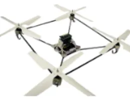
Fig. 1.The X4-flyer.
decouple the navigation part (considered in the inner loop) from high-level tasks, interacting with the environment. For example using an embedded camera which sends the images to a ground station implies time delays and then a slow image based control loop. It is thus necessary to have a lower-level loop to ensure stabilisation. An other advantage to consider the high-level loop is to enable easier re-use of the IBVS scheme, since it is not closed to the material equipment of the aerial vehicle.
Following earlier work [22, 15], we have chosen to use zero and first order image moments as primary visual features for the control design. Perspective projection moments with suitable scaling along with a classical IBVS control design lead to satisfactory transients and asymptotic stability of the closed-loop system when the image plane remains parallel to the target. However, the system response may lack robustness for aggressive manoeuvres. In order to overcome this problem, new control schemes, based on spherical first order image moments, have been proposed [23]. In [23], the experimental results had been obtained on a 6 degrees of freedom robot arm, whereas we present in this paper experimental results on a quadrotor. Note that [19] deals with dynamic control whereas we consider kinematics translation control.
The goal of this paper is to experiment and compare a range of kinematic image based control schemes with a quadrotor aerial vehicle named X4-flyer (Fig.1), an omnidirectional VTOL
(ver-tical take off and landing) vehicle ideally suited for stationary and quasi-stationary flight conditions. The task considered is to reach a desired position with respect to a specified target. This paper is organized as follows: in Section 2 the X4-flyer is described, and the experimental conditions used in all experi-ments are given. In Section 3 perspective zeroth and first order image moments are used to control the translation kinematics of the X4-flyer prototype. In Section 4 spherical first order image moments and a range of related control schemes are presented. Experimental results are analysed and compared in each section.
2. EXPERIMENTAL CONDITIONS
2.1 Prototype description
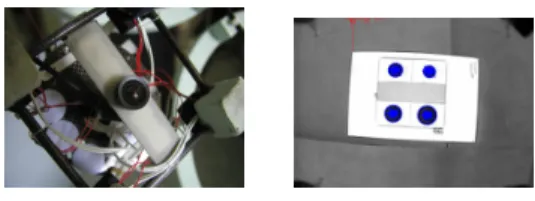
The unmanned aerial vehicle (UAV) used for the experimenta-tions is an X4-flyer (Fig.1), that is an omnidirectional VTOL vehicle ideally suited for stationary and quasi-stationary flight conditions. It consists of four fixed pitch propellers linked to an electrical motor at each extremity of a cross frame (Fig. 1). The vehicle is equipped with an avionics stack including an Inertial Measurement Unit (IMU) supplying the vehicle attitude and a controller board [24, 21]. A wireless link allows the transmission of the attitude command between the X4-flyer and a ground station (Pentium 4). A camera situated below the X4-flyer (Fig. 2.a) is embedded and observes a target on the ground, consisting of four black marks on the vertices of a planar rectangle (30 × 40 cm) (Fig. 2.b). A wireless analogue link transmits camera images to the ground station. A 3D estimation of the vehicle position with respect to the target is obtained by fusing the data of the embedded IMU and the visual data in a particle filter [25]. This estimate is used to provide an estimate of ground truth for the 3D behaviour of the vehicle and to provide an estimate of the linear velocity of the vehicle that is used by the high-gain controller of the airframe dynamics. In this paper, only 2D visual information is used in the outer IBVS control loop for position regulation. All the visual servo controls tested are implemented on the ground station. The outer IBVS control loop provides desired translational velocity. This velocity is considered as a set point for an inner control loop, which regulates the rotational dynamics of the vehicle. Time-scale separation and high gain arguments can be used to ensure stability of the closed-loop system.
(a) (b)
Fig. 2.(a) The camera. (b) The target view from the camera. 2.2 Experimental protocol
In order to compare the proposed different kinematic visual servo controls, the initial conditions of the experiments were chosen identically. For each experiment, the X4-flyer was servo controlled to a specific initial position using a standard state-space controller deriving information from the task state-space posi-tion estimate. When the vehicle is stabilised at this posiposi-tion, the visual control is initiated and the 3D position, obtained from a particle filter, is recorded. This protocol ensures that the flight conditions are the same and allows the comparison between the different proposed controllers. The velocity demand is also
saturated at 20 cm/s to ensure the vehicle remains in quasi-stationary flight regime [26]. The gains of different control laws have been tuned so that the X and Y positions converge in about 10 seconds.
3. VISUAL SERVO CONTROL USING PERSPECTIVE IMAGE MOMENTS
In this section, we use the perspective zeroth and first order image moments [22] to control the translational displacement of the X4-flyer. These image features provide a linear and decoupled link between the task space and the image space, which allows to ensure a good 3D behaviour.
Let A denote the inertial or task space reference frame and let C denote the camera or body-fixed reference frame.
Let us define the visual feature vector s = (xn, yn, an)such
that
an= Z∗
r a∗
a, xn = anxg, yn= anyg
where xg and yg are the centroid coordinates of the object
in the image, a is the area of the object in the image, a∗
is its desired value and Z∗ is the desired depth between the
camera and the target. The time derivative of s and the relative motion between the camera and the object can be related by the classical equation:
˙s = Lυυ+ Lωω
where υ and ω are respectively the linear and angular velocity of the camera both expressed in the camera frame, and where Lυand Lωare respectively the parts of the interaction matrix
related to the translational and the rotational motions. The desired image feature is denoted by s∗
∈ C, and the visual error is defined by e = s − s∗.
Classical image based visual servo control design aims to im-pose linear exponential stability on the image error kinemat-ics [1, 22] to ensure an exponential decoupled decrease for e ( ˙e = −λe, with λ a positive constant). Using e to control the translational degrees of freedom, the classical IBVS control input is:
υ= −(Lυ)−1(λe + Lωω), λ >0. (1)
Generally, the interaction terms Lυ and Lω depend
non-linearly on the state of the system and cannot be reconstructed exactly from the observed visual data. The visual feature s = (xn, yn, an) is of particular interest since Lυ = −I3 in the
case where the camera image plane is parallel to the target plane [22]. In the application considered in this paper, the camera is mounted to point directly downward in the X4-flyer and the image and target plane are never more than a couple of degrees offset. As a consequence, the approximation Lυ≈ −I3
is valid. The control law is thus simplified to
υ= λe + Lωω, λ >0. (2)
Since the link between image space and task space is almost linear and decoupled (Lυ≈ −I3), this control scheme is known
to lead to satisfactory closed-loop behaviour for holonomic robot [22]. It is in fact equivalent to a position-based visual servo, but without any pose estimation required.
The motion of the X4-flyer is smooth and slow and the value of Lωω is small compared with the error λe in (2). Thus, a
reasonable approximation of (2) for the purposes of this paper is
Equation (3) does not require the estimation of any 3D parame-ters and can be implemented based only on the observed image features s. This control was implemented on the experimental platform. 0 5 10 15 20 25 −0.5 0 0.5 1 1.5 2 2.5 3 X Y Z 0 5 10 15 20 25 −0.2 −0.15 −0.1 −0.05 0 0.05 0.1 0.15
0.2 Velocity: output of the control law (m/s)
time (s) υx υy υz (a) (b) 0 5 10 15 20 25 −1 −0.5 0 0.5 1 1.5 Visual error: e time (s) e x e y e z
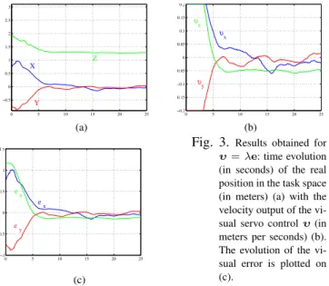
Fig. 3. Results obtained for υ = λe: time evolution (in seconds) of the real position in the task space (in meters) (a) with the velocity output of the vi-sual servo control υ (in meters per seconds) (b). The evolution of the vi-sual error is plotted on (c).
(c)
The practical results are very satisfactory (see Fig. 3) : the vehicle has actually a very good behaviour in each direction. Moreover, the control law is a simple proportional control, and, as the visual error design needs only visual data, it is very easily implemented.
The limitation of this approach, however, lies in its dependence on the particular geometry of the application considered and the requirement to consider only smooth slow trajectories of the vehicle. If the vehicle undertakes aggressive manoeuvres, or the parallel target plane assumption is invalidated for a particular application, the approximation Lυ ≈ −I3 will fail and more
importantly the approximation Lωω ≈ 0 may also fail. This
second issue introduces a significant dynamic disturbance in the system response that cannot be cancelled directly without the risk of introducing zero dynamic effects into the closed-loop response similar to those studied in recent works [20, 27]. The potential limitations of the classical IBVS control design based on perspective projection features motivate us to consider a class of spherical projection features and non-linear control design techniques.
4. VISUAL SERVO CONTROL USING SPHERICAL PROJECTION
4.1 Image based feature
In this section we use an un-normalised first order spherical image moment along with an inertial goal vector [15] that al-lows us to obtain the desirable passivity property. This passivity property is very interesting in order to control an under-actuated vehicle such as the X4-flyer [15].
Consider a point target consisting of n points {Pi} ∈ C
corresponding to image points on the spherical plane {pi}. The
centroid of the target is defined to be
q:=
n
X
i=1
pi∈ <3. (4)
For a point target comprising a finite number of image points the kinematics of the image centroid are easily verified to be [15] ˙q = −ω × q − Qυ, (5) with Q = Pi=n i=1 π pi |Pi|where πp= (I3−pp T). Note that Q is a
positive definite matrix if there are at least two different points piin the image space (see [15] for more details).
Let b ∈ A denote the fixed set point for visual feature q. The feature q is measured relative to the camera frame and not in the inertial frame, and it is necessary to map the desired set point into the camera frame before an image based error can be defined.
Let q∗ := R>b ∈ C, where rotation matrix R between
the camera frame and the inertial frame is obtained from the data supplied by the embedded IMU. The image based error considered is
δ:= q − q∗. (6) Since q∗ ∈ C, it inherits dynamics from the motion of the
camera: ˙q∗ = −ω × q∗. Thus, the image error kinematics
are [15]
˙δ = δ × ω − Qυ (7) from which we deduce ˙|δ| = −δ>|δ|Qυ. Since |δ| is a function
of position only, its behaviour will thus not be perturbed by the camera rotational motions. That is why the visual feature δ seems to be very interesting to control an X4-flyer.
In the following subsections, a range of control design for the translational motion of the X4-flyer based on the visual feature qis considered. Some of them have already been theoretically developped in [23], but we did not have experimented them on an aerial vehicle. In this paper experimental results using an X4-flyer prototype are provided. Moreover the results are compared with the classical IBVS control design based on perspective image moments presented in Section 3.
For each experimentation, the asymptotic value to reach for Q is
Q∗= diag(2.35, 2.36, 0.057) (8) and we have b ∼= (0, 0, 3.96). These values have been com-puted when the vehicle is situated at the desired position: ap-proximatively above the center of the target at 1.4 m height of the ground.
4.2 Asymptotic compensation
Linearization at the set point. Using pure proportionnal feed-back of the un-normalized centroid ensures global asymptotic stability, but does not give suitable behaviour [23]. The problem is that the eigenvalues of the matrix Q are not the same and in the general case λmin(Q) << λmax(Q) (where λmin and
λminare respectively the smallest and largest eigenvalues). This
means that convergence rates of the components of δ are not the same and the component which is affected by the eigenvalue λmin(Q)is more sensitive to perturbations. By computing
ma-trix Q at the desired position (Q∗), it follows that λ
minis the
third eigenvalue of matrix Q (see (8)). The third component of q(or δ) is thus sensitive to perturbations. So, it is important that the control schemes designed compensate this sensitivity problem. The first idea to compensate the poor sensitivity is to use the inverse interaction matrix [23] as in classical IBVS. Indeed the control law υ = kQQ−1δ, kQ > 0 yields
˙
function defined by L = 1
2|δ|2. This choice guarantees global
asymptotic stability and equal convergence rates. The problem is that the matrix Q−1 is not exactly known, since it depends
on the 3D depths |Pi|. Thus we can not use easily this control
law.
The idea is then to use the desired interaction matrix Q∗ [23]
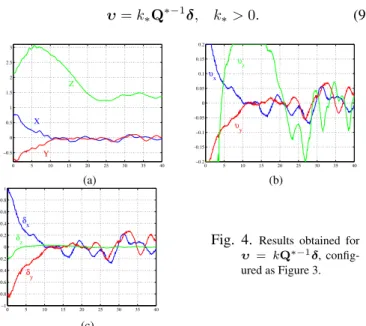
instead of the current interaction matrix Q, as it is often done in classical IBVS: υ= k∗Q∗−1δ, k∗>0. (9) 0 5 10 15 20 25 30 35 40 −0.5 0 0.5 1 1.5 2 2.5 3 X Y Z 0 5 10 15 20 25 30 35 40 −0.2 −0.15 −0.1 −0.05 0 0.05 0.1 0.15
0.2 Velocity: output of the control law (m/s)
time (s) υx υy υz (a) (b) 0 5 10 15 20 25 30 35 40 −1 −0.8 −0.6 −0.4 −0.2 0 0.2 0.4 0.6 0.8 1 Visual error: δ time (s) δx δy
δz Fig. 4. Results obtained for
υ = kQ∗−1δ, config-ured as Figure 3.
(c)
As can be seen on Fig. 4, this control law enables the conver-gence of all the visual error components. However, as the matrix Q is never updated during the vehicle evolution and fixed to Q∗, this control scheme is not adequate far from the desired position. Consequently, we can see that the convergence rate is not the same on the three components of the position (Fig. 4.a) and the Z component is not suitable. That is why we experiment another approach in the next subsection.
Partitioned control. A second idea for compensating the relative poor sensitivity in the control design is to modify the visual error term in keeping the passivity-like properties. Since difficulties observed in control designs presented in the previous section result from sensitivity in the z-axis, a possible solution is to use a partitioned approach by singling out the problematic component for a special treatment [28].
We separate the visual error term into two criteria with different sensitivity. Two new error terms are introduced in order to compensate the poor sensitivity of q:
δ11= sk(q∗
0)q, δ12= q∗>0 δ, with q∗0=
q∗ |q∗|.
Note that due to the properties of the skew symmetric matrix sk(q∗
0), δ11 and q∗0δ12 are orthogonal. δ12is the projection of
the error δ along the q∗direction.
Deriving δ11and δ12, it follows that
˙δ11= −sk(ω)δ11− sk(q∗
0)Qυ, (10)
˙δ12= −q∗>0 Qυ. (11)
Let us define as Lyapunov function L such that
L = 12(|δ11|2+ λ2δ212) (12)
where λ is a constant chosen as shown below. It is straightfor-ward to verify that L = 1
2|δA|2, with
δA= δ11+ λq∗
0δ12. (13)
Deriving (12), recalling (10), (11), and substituting for (13), one obtains
˙
L = −δ>AA(q∗0)Qυ (14)
where A(q∗
0) = sk(q∗0) + λq∗0q∗>0 . We define the following
control input
υ= kAA(q∗
0)>δA, kA>0. (15)
Recalling (14) and substituting the control input υ by its ex-pression yields
˙
L = −kAδ>AA(q0∗)QA(q∗0)>δA.
Since Q is a positive definite matrix and A(q∗
0)a non singular
matrix, A(q∗
0)QA(q∗0)> > 0 and therefore δA converges
exponentially to zero. Consequently, δ11 and δ12 converge
exponentially to zero (see (13)). Exponential convergence of the initial error δ to zero is guaranteed.
Note that the best choice of the gain λ is characterized by the following constraint: A(q∗
0)Q∗A(q∗0)> ∼= I3. where the
symbol ∼= means “equality up to a multiplicative constant”. This choice ensures asymptotically equivalent convergence rate for all the components of the error δA. λ = 6.44 was used
for the presented experimentation; it gave A(q∗
0)Q∗A(q∗0)>' 2.35I3. 0 5 10 15 20 25 30 35 40 −0.5 0 0.5 1 1.5 2 2.5 3 Measured position time (s) X Y Z 0 5 10 15 20 25 30 35 40 −0.2 −0.15 −0.1 −0.05 0 0.05 0.1 0.15
0.2 Velocity: output of the control law (m/s)
time (s) υx υy υz (a) (b) 0 5 10 15 20 25 30 35 40 −1 −0.8 −0.6 −0.4 −0.2 0 0.2 0.4 0.6 0.8 1 Visual error: δ1 temps(s) δAx δAy δAz
Fig. 5. Results obtained for υ= kA(q∗
0)>δ1,
con-figured as Figure 3.
(c)
At the view of the Fig.5, we can see that although the initial position is far from the set point, this control law enables the convergence of all the visual error components. However the dynamic behaviour of the Z component is strange and consequently, the control law is not perfectly suitable.
4.3 Global compensation using rescaled image feature
The previous control schemes use the desired position in order to equalize the dynamics of the control law: in Section 4.2.1 the desired interaction matrix Q∗ was used, and in Section 4.2.2
the visual error was projected on the direction of the desired visual feature q∗. However the asymptotic compensation is not
suitable during the transient, and the behaviour of the X4-flyer is not satisfactory.
In [23], we have shown that a rescaled image feature allow to improve the results, with suitable transient and asymptotic behaviour. In the following subsections, we recall the basics and analyse the new experimental results.
Proportionnal control law with rescaled image feature. The visual error δf is defined as follows:
δf = F (|q|)q0− F (|q∗|)q∗
0
It incorporates the normalised first order moments q0 = |q|q
along with the scaled ”depth” parameter F (|q|) defined by: F(|q|) := a|q|
pn2− |q|2 (16)
where n is the number of points observed and a is the ap-proximate radius of the target. This parameter ensures that the link between task space and image space is almost linear. Consequently the image based visual servoing will give similar behaviour in image space as in task space (see [23] for more details).
Thus we design the control law such that the convergence rates of the components of the visual error δf are very close.
Taking the time derivative of the storage function L = 1 2|δf|2
yields after developments: ˙L = −δ>f MQυ.
Note that the matrix M is such that MQ ' I3[23].
Thus an intuitive idea is to design the control law such that the convergence rates are given by the eigenvalues of MQ. We choose
υ= kfδf, kf >0 (17) in order to obtain for the derivative of the storage function: ˙L = −kfδ>f MQδf. This form of the storage function ensures the
desired property, since the convergence rate of the components of the visual error δf are given by the eigenvalues of MQ.
Theoretically this control scheme gives approximately the same convergence rate for the components of the visual error. More-over, the image feature is chosen close to the 3D position, in order to have a good 3D behaviour with same convergence rate for the components of the 3D position.
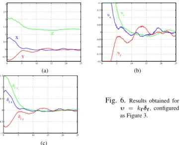
As expected, the transient behaviour of the X4-flyer is very good and the three components converge at equal rates in image space (see Fig. 6.c) and in task space (see Fig. 6.a). Moreover, the asymptotic behaviour of the velocity control is less disturbed than previously (see Fig. 6.b, Fig. 4.b, and Fig. 5.b).
Its advantage is also that it is easily implemented, since the control law is a direct function of the visual error δf.
Since this control law preserves the passivity property, it is ex-pected to be well-adapted for wide range of aerial vehicles and experimental conditions. However, similar to the perspective moments control design, the global asymptotic stability has not been demonstrated because we are not sure to have MQ > 0 in all the task space.
Globally asymptotically stable control law with modified resca-led image feature. In [23] we proposed a control law based on the ”depth” parameter F (|q|) (defined by (16)), which ensures suitable image space and task space convergence, in addition to global asymptotic stability.
The new visual error δgis defined as follows:
δg= G(|q|)q0− G(|q∗|)q∗0 (18) where G(|q|) = α(|q|)p|q|F (|q|) and α(|q|) is chosen such that α(|q∗|) = 1. 0 5 10 15 20 25 −0.5 0 0.5 1 1.5 2 2.5 3 X Y Z 0 5 10 15 20 25 −0.2 −0.15 −0.1 −0.05 0 0.05 0.1 0.15
0.2 Velocity: output of the control law (m/s)
time (s) υx υy υz (a) (b) 0 5 10 15 20 25 −1 −0.5 0 0.5 1 1.5 Visual error: δf time (s) δfx δfy δfz
Fig. 6. Results obtained for υ = kfδf, configured
as Figure 3.
(c)
Taking the time derivative of the storage function L = 1 2|δg|
2
yields after developments ˙L = −δ>gHQυwith H = α(|q|)
√ M. Thus, if we choose as control law
υ = kg
α(|q|)2H(q)δg, kg>0 (19)
the derivative of the storage function becomes ˙
L = − kgδ>g
H(q)QH(q) α(|q|)2 δg.
Since Q is a positive definite matrix, classical Lyapunov the-ory guarantees that δg converges exponentially to zero. Since
α(|q∗|) = 1, we have HQH
α(|q|)2 ' I3 and consequently good
convergence rates in image space (see [23] for more details). Suitable task space behaviour is ensured by the visual feature choice.
As can be seen on Fig. 7, this control scheme leads to equal convergence rates of the visual error components, and equal convergence rates in the task space. The transient behaviour is acceptable.
This control law ensures good behaviour as well as the the-oretical important properties of global asymptotic stability and passivity. However the linear link between task space and image space is destroyed, and this could lead to undesirable transient behaviour in some situations.
0 5 10 15 20 25 −0.5 0 0.5 1 1.5 2 2.5 3 X Y Z 0 5 10 15 20 25 −0.2 −0.15 −0.1 −0.05 0 0.05 0.1 0.15
0.2 Velocity: output of the control law (m/s)
time (s) υx υy υz (a) (b) 0 5 10 15 20 25 −1 −0.5 0 0.5 1 1.5 Visual error: δg time (s) δgx δgy
δgz Fig. 7.υ Results obtained for
= kg
α2Hδg,
config-ured as Figure 3.
5. CONCLUSION
This paper presented experimental results for kinematic IBVS control of an X4-flyer. Since they have desirable properties, image moments have been used as visual features. Experimen-tal results have been shown, analyzed and compared for each proposed control scheme.
Using the well-known perspective image moments to design a classical IBVS translational control law leads to a good system behaviour in the undertaken experimental studies. However this control scheme does not ensure global asymptotic stability or passivity of the closed-loop system.
Using spherical first order image moments along with an iner-tial goal vector allows us to design translational control laws independent from the rotation motion. Global asymptotic sta-bility can be obtained by using these visual features and a simple proportional feedback, but the behaviour on the z-axis is not acceptable. Asymptotic compensation by using classical linearization at the set point or partitionned control give better results but bad transient behaviour: while the X4-flyer has to go down, it starts to go up at the beginning of the control. Suitable feature rescaling allows to compensate globally the sensitivity problem and to improve this behaviour. However, one of the suitable control law does not ensure global asymtotic stability, and the other one does not preserve the linear link between task space and image space.
Finally, the perspective image moments control design, as well as the globally compensated control laws using spherical image moments lead to an acceptable behaviour of the system. None of these three control schemes can be said better than the others, but each one has different theoretical properties.
ACKNOWLEDGEMENTS
This work was supported by CNRS under the project ROBEA-Robvolint.
REFERENCES
[1] B. Espiau, F. Chaumette and P. Rives. A new approach to visual servoing in robotics. IEEE Trans. on Rob. and
Autom., 8(3):313–326, 1992.
[2] F. Chaumette and S. Hutchinson. Visual servo control, part I: basic approaches. IEEE Rob. and Autom. Mag., 13(4):82–90, Dec. 2006.
[3] K. Hatano and K. Hashimoto. Image-based visual servo using zoom mechanism. SICE 2003 Annual Conf.,
3:2443–2446, Aug. 2003.
[4] E. Altu˘g, J.P. Ostrowski and C.J. Taylor. Control of a quadrotor helicopter using dual camera visual feedback.
IJRR, 24(5),329–341, Sage Publications, Inc., Thousand
Oaks, USA, 2005.
[5] H. Romero, R. Benosman and R. Lozano. Stabilization and location of a four rotor helicopter applying vision.
ACC, 3930–3936, Minneapolis, USA, June 2006.
[6] O. Amidi, T. Kanade and K. Fujita. A visual odometer for autonomous helicopter flight. J. of Rob. and Aut. Sys., 28:186–193, Aug. 1999.
[7] K. Nordberg, P. Doherty, G. Farnebck, P.E. Forssn, G. Granlund, A. Moe and J. Wiklund. Vision for a UAV helicopter. IROS, workshop on aerial robotics, Lausanne, Switzerland, Oct. 2002.
[8] S. Saripalli, J.F. Montgomery and G.S. Sukhatme. Visually-guided landing of an UAV. IEEE Trans. on Rob.
and Autom., 19(3):371–381, June 2003.
[9] A.D. Wu, E.N. Johnson and A.A. Proctor. Vision-aided inertial navigation for flight control, AIAA Guidance,
Nav-igation, and Control Conf. and Exhibit, San Francisco,
USA, Aug. 2005.
[10] J.R. Azinheira, P. Rives, J.R.H Carvalho, G.F. Silveira, E.C. de Paiva and S. S Bueno. Visual servo control for the hovering of an outdoor robotic airship. ICRA, 3:2787– 2792, Washington, USA, May 2002.
[11] H. Zhang and J.P. Ostrowski. Visual servoing with dy-namics: control of an unmanned blimp. ICRA, 618–623, Detroit, USA, May 1999.
[12] P. Rives and J.R. Azinheira. Visual auto-landing of an autonomous aircraft. Research Rep., INRIA-Sophia
Antipolis, n. 4606, Nov. 2002.
[13] O. Bourquardez and F. Chaumette. Visual servoing of an airplane for auto-landing. IROS, San Diego, USA, Oct. 2007.
[14] O. Shakernia, Y. Ma, T. Koo and S Sastry. Landing an UAV: Vision based motion estimation and nonlinear control. Asian J. of Control, 1(3):128–145, Sept. 1999. [15] T. Hamel and R. Mahony. Visual servoing of an
under-actuated dynamic rigid-body system: An image based approach. ITRO, 18(2):187-198, Apr. 2002.
[16] P.I. Corke and M.C. Good. Dynamic effects in visual closed-loop systems. IEEE Trans. on Rob. and Autom., 12(5):671–683, 1996.
[17] J. Gangloff and M. de Mathelin. Visual servoing of a 6 DOF manipulator for unknown 3D profile following.
IEEE Trans. on Rob. and Autom., Aug. 2002.
[18] R. Kelly, R. Carelli, O. Nasisi, B. Kuchen and F. Reyes. Stable visual servoing of camera-in-hand robotic systems.
IEEE/ASME Trans. on Mech., 5(1):39–48, Mar. 2000.
[19] N. Guenard, T. Hamel and R. Mahony. A practical Visual Servo Control for a UAV. ITRO, April 2007.
[20] E. Frazzoli, M.A. Dahleh and E. Feron. Real-time motion planning for agile autonomous vehicles. J. Guidance
Cont. and Dyn., 25(1):116-129, 2002.
[21] N. Guenard, T. Hamel and L. Eck. Control law for the tele operation of an UAV known as an X4-flyer. IROS, Beijing, China, Oct. 2006.
[22] O. Tahri and F. Chaumette. Point-based and region-based image moments for visual servoing of planar objects.
ITRO, 21(6):1116-1127, Dec. 2005.
[23] O. Bourquardez, R. Mahony, T. Hamel and F. Chaumette. Stability and performance of image based visual servo control using first order spherical image moments. IROS, Beijing, China, Oct. 2006.
[24] N. Guenard, T. Hamel and V. Moreau. Dynamic modeling and intuitive control strategy for an X4-flyer, Int. Conf.on
Cont. and Autom., Budapest, Hongrie, June 2005.
[25] S. Arulampalam, S. Maskell, N.J. Gordon and T. Clapp. A tutorial on particle filters for on-line non-linear/non-gaussian bayesian tracking. IEEE Trans. of Signal
Pro-cessing, 50(2):174-188, Feb. 2002.
[26] N. Guenard, T. Hamel, V. Moreau and R. Mahony. Design of a controller allowed the intuitive control of an X4-flyer.
Int. IFAC Symp. on Rob. Cont., Bologna, Italy, Sept. 2006.
[27] T. Hamel and R. Mahony. Image based visual servo-control for a class of aerial robotic systems. To appear
in Automatica, 2007.
[28] P. Corke and S.A. Hutchinson. A new partitioned ap-proach to image-based visual servo control. IEEE Trans.