HAL Id: hal-02511875
https://hal.archives-ouvertes.fr/hal-02511875
Submitted on 19 Mar 2020
HAL is a multi-disciplinary open access
archive for the deposit and dissemination of sci-entific research documents, whether they are pub-lished or not. The documents may come from teaching and research institutions in France or abroad, or from public or private research centers.
L’archive ouverte pluridisciplinaire HAL, est destinée au dépôt et à la diffusion de documents scientifiques de niveau recherche, publiés ou non, émanant des établissements d’enseignement et de recherche français ou étrangers, des laboratoires publics ou privés.
A numerical model to predict the effect of corrosion on
the dynamic behavior of reinforced concrete beams
Chaymaa Lejouad, Sophie Capdevielle, Benjamin Richard, Frédéric
Ragueneau
To cite this version:
Chaymaa Lejouad, Sophie Capdevielle, Benjamin Richard, Frédéric Ragueneau. A numerical model to predict the effect of corrosion on the dynamic behavior of reinforced concrete beams. 12th Canadian Conference of Earthquake Engineering, Jun 2019, Québec, Canada. �hal-02511875�
1
A numerical model to predict the effect of corrosion on the dynamic behavior of reinforced
concrete beams
Chaymaa Lejouad1, Sophie Capdevielle 2, Benjamin Richard 3, Frédéric Ragueneau4
1 Ph.D. Student, Atomic Energy and Alternative Energies Commission, F-91191 Gif-sur-Yvette, France. 2 Assistant professor, LMT, ENS Paris-Saclay, CNRS, Université Paris-Saclay, F-94235 Cachan, France. 3 Head of the Structural Performance Modeling and Analysis Laboratory, IRSN, F-92260 Fontenay- aux-Roses, France.
4 Professor, LMT, ENS Paris-Saclay, CNRS, Université Paris-Saclay, F-94235 Cachan, France.
ABSTRACT
Corrosion of the steel reinforcements has been identified as one of the major pathologies which may occur in reinforced concrete (RC) structure. The objective of this study is to develop an efficient computational model of RC members, accounting for the rebar corrosion. Fiber beam elements are known for being efficient to carry out computations at a structural scale with a relatively low computational cost. The purpose of the present study is thus to take corrosion effects into account in a fiber beam element computation.
The first requirement for the developed model is the ability to represent the damage induced in the concrete cover due to the swelling of the steel corroded bar. Therefore, an initial computation conducted on a fine mesh cross-section provides a precise damage field, which needs to be projected on a coarser mesh. This coarser mesh will be used in fiber beam elements for computations at the structural scale, in order to stay consistent with the requirement of a low computational cost.
In this study, two field projection techniques are investigated. The first proposed approach is based on the use of the shape functions. An optimization algorithm is suggested to improve the projection results, namely the stiffness matrix at the cross-section scale. The optimization improves the results of the projection method, but does not enable the use of a mesh coarse enough to be included in fiber-beam elements for a dynamic computation. Thus, a second projection procedure is investigated, based upon diffuse approximation. Combined with the proposed optimization, this method leads to satisfying results at the cross-section scale. The projected damage fields have been used to compute the non-linear force-displacement curve of a beam subject to three-point bending. This test confirms the choice of the projection method.
Keywords: reinforced concrete, corrosion, earthquake engineering, fiber beam elements, dynamic behavior INTRODUCTION
To assess the seismic vulnerability of existing – and aging – reinforced concrete (RC) structures, the effects of pathologies need to be taken into account. The steel reinforcement corrosion is one of the most threatening pathologies for the structural safety of existing RC buildings. This statement is particularly true when this pathology is combined with the seismic risk. Therefore, the simulation of the dynamic behavior of affected RC structures is of major importance. The purpose of this study is to develop a numerical model able to predict the dynamic response of corroded RC members. The model should be relatively inexpensive in terms of computational time, so that it can be used for probabilistic safety studies (PSA) applications.
The main challenge of such a numerical model is to carry out computations at the structural scale, while accounting for the material non-linearities. Fiber beam elements have been proved to be a robust and efficient approach [1] [2] [3] [4] [5]. Based upon Timoshenko beam elements, the multifiber method allows to take into account an additional scale which is defined at the cross-section level. From the generalized strains, strains in the cross section are computed according to a kinematics assumption. Stresses are obtained from the strains at each integration point of the cross-section by a constitutive law. This enables the access to refined information on the material behavior. By integrating the stresses over the cross-section, generalized forces are computed. The present contribution proposes to enhance fiber beam elements to take into account the mechanical consequences related to the corrosion phenomenon as an initial state.
Due to the expansive nature of the corrosion products, concrete is subjected to high stresses at the steel/concrete interface. Indeed, rust product at the steel/concrete interface swell when appearing. The first step of the numerical model consists in
12th Canadian Conference on Earthquake Engineering, Quebec City, June 17-20, 2019
2
considering the concrete damage state induced by the rebars swelling. In the proposed approach, concrete damage is first computed in a 2D-meshed cross-section. The model to represent the corroded rebars is described in the first part. A fine mesh is used, to precisely compute the damage state of the cross-section. However, to save time in computing the seismic response of the structure, a coarser mesh needs to be used for the cross-section of fiber beam elements. Thus, the so-obtained damage field needs to be projected on the coarser mesh. Two projection methods are investigated in this paper, presented in the second part. The first method is based upon the use of the shape functions of both meshes [6]. The second one is based on the diffuse approximation of the damage field [7]. For both methods, an optimization procedure is proposed, to improve the results of the projection at the cross-section scale. To conclude on the projection method, the behavior of a beam subjected to a three-point bending test is eventually computed and presented in the last part of the paper. The force-displacement curves of the beam at different cross-section configurations (damage field computed by both projection methods, damage fields optimized with the proposed method) are presented and compared to the behavior of the finely meshed cross-section beam.
MODEL FOR THE CROSS-SECTION WITH CORRODED REBARS
Steel corrosion induces an expansion of the rebars, leading to concrete damage. The increase in volume of the corrosion products, compared to the initial volume of steel is given by the expansion factor 𝛼 (equation (1)). 𝑉#$ denotes the volume of
the corrosion products, and 𝑉% the corresponding volume of steel.
𝛼 = 𝑉#$
𝑉% (1)
On the other hand, corrosion is characterized by a corrosion rate 𝜏, defined as a steel mass loss 𝛥𝑀 relative to the initial mass 𝑀.. 𝜏 is expressed in equation (2). The mass loss is directly linked to the mass of steel transformed into corrosion products
𝑀%#. In this way, we can express the volume of the rebar steel subject to corrosion, given a corrosion rate, in equation (3). 𝑉. is
the initial volume of the uncorroded rebar. The volume of the corrosion products on the rebar is given in equation (4). 𝜏 =− Δ𝑀 𝑀. = M23 𝑀. (2) 𝑉%#= 𝜏 𝑉. (3) 𝑉#$= 𝛼 𝑉%# (4)
The volume increase of the rebar can be expressed as the difference between the volume of the corrosion products and the volume of steel which has been corroded:
𝑉#$− 𝑉%# = (𝛼 − 1) 𝑉%# = (𝛼 − 1) 𝜏 𝑉. (5)
To characterize the rebar expansion, we need to compute the difference between the final radius of the corroded rebar 𝑟# and
the initial radius of the rebar 𝑟.. From equation (5), and accounting from the remaining volume of healthy steel, one can write:
𝜋 𝑟#:− 𝜋 𝑟.:= (𝛼 − 1) 𝜏 𝜋 𝑟.: (6)
𝑟#:= <(𝛼 − 1) 𝜏 + 1> 𝑟.: (7)
Δ𝑟 = 𝑟#− 𝑟.= @A(𝛼 − 1) 𝜏 + 1 − 1B 𝑟. (8)
This difference in radius will be used to numerically compute the concrete damage due to the expansion of the corroded rebar. The concrete cross-section is modeled as a 2D domain, meshed by linear triangles, as represented in Figure 1. A fine mesh formed of 5232 elements is chosen, to precisely represent the damage field in the cross-section. Concrete is described by the Mazars damage model [8]. The spatial variability of concrete is taken into account through a random distribution [9] of the Young modulus around a mean of 36.5 GPa, generated using the turning bands method.
3
Figure 1: Fine mesh for the computation of the CS damage due to the rebars corrosion.
The interface with the four longitudinal rebars is modeled as joint elements [10]. The expansion of the rebars is represented by prescribing relative displacements at the steel/concrete interface, with a coefficient calibrated to match the Δ𝑟 computed in equation (8). Different corrosion products may be generated by the corrosion process, depending on the oxygen content, the pH, the chloride percentage... [11] [12] [13] [14] [15]. The corrosion products have different densities, which leads to a different value of 𝛼 for each case. 𝛼 may vary between 2 and 7 [16]. Here, an expansion rate 𝛼 of 3,8 has been chosen, with a high corrosion rate 𝜏 of 29%. According to equation (8), a displacement Δ𝑟 = 1.9 mm has been applied to the joint elements through the thermal expansion. The damage field after the expansion of the rebars is computed thanks to the Cast3M software [17]. The result is represented in Figure 2. The damage field seems spread out over many elements, which is explained by the high chosen corrosion rate. The computation is used as a reference to test the development of the projection field technique.
Figure 2: Damage field due to the rebar expansion, for the fine mesh.
PROJECTION OF THE DAMAGE FIELD
The damage distribution computed in the previous part will be used as the initial state for concrete to compute the behavior of a beam subjected to a seismic loading. However, the mesh represented in Figure 1 is too fine to be used to compute the beam behavior within the framework of PSA. For the sake of computational efficiency, a coarser mesh needs to be used to discretize the fiber beam element cross section. Thus, the computed damage field needs to be projected on the coarser mesh. Two projection methods are investigated. The first one is based upon the use of the shape functions to compute the initial damage field on the coarser mesh. An optimization method based upon the section stiffness matrix is then proposed. The second method is based upon diffuse approximation [7], also improved with the proposed optimization procedure.
12th Canadian Conference on Earthquake Engineering, Quebec City, June 17-20, 2019
4
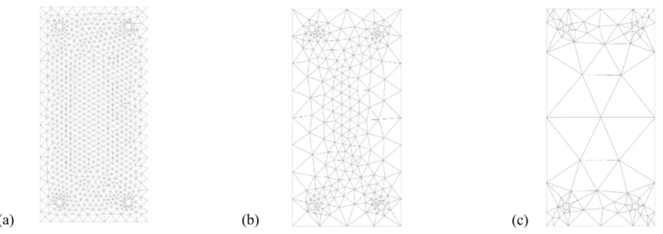
Both methods have been implemented in the CastLab toolbox [18]. They have been tested using three coarser meshes which are represented in Figure 3. Unstructured meshes with a variable density are chosen to better represent the material behavior around the rebars.
Figure 3: Coarser meshes used to test the projection techniques. (a) Mesh 1: 1686 elements. (b) Mesh 2: 452 elements. (c) Mesh 3: 156 elements.
Projection method based upon the shape functions
From the damage field obtained by the mechanical computation using a fine mesh, the damage field in the cross-section meshed with less elements needs to be computed. The first proposal lies in a projection method based upon the use of shape functions. The damage field represented in Figure 2 is computed and “stored” in the cross-section integration points. Using the fine mesh shape functions, damage values are computed at the nodes of the fine mesh. Then, using the shape functions of the coarser mesh, the damage values are calculated in the integration points of the coarser mesh cross-section. Because the projection inevitably modifies the cross-section stiffness matrix, it is necessary to reduce the resulting gap. To address this issue, an optimization procedure is proposed. It consists in multiplying the initially projected damage field 𝑫𝟎 by a scalar 𝑎 to obtain the
new projected damage field 𝑫 = 𝑎 𝑫𝟎, with the aim of minimizing ‖ 𝐾%,LMN− 𝐾%,#OPL%M(𝑫) ‖. 𝐾%,LMN is the stiffness matrix of
the reference cross-section, meshed by the very fine mesh. 𝐾%,#OPL%M(𝑫) is the stiffness matrix of the coarse cross-section,
computed with the damage field 𝑫. In the case 𝐾%,#OPL%M(𝑫𝟎) is stiffer than 𝐾%,LMN, 𝑎 needs to be greater than 1. In this case, the
values of 𝑫 are limited to 1 during the optimization process.
This method is tested on the three coarser meshes represented in Figure 3. Then the optimization procedure is applied. Figure 4presents the damage fields obtained after the first projection. Figure 5 presents the damage fields obtained after optimization.
Figure 4: Damage fields obtained after projection by the method based upon the shape functions.Champ projeté Cast3M − Fonctions d interpolation D > 0.00E+00 < 1.00E+00 3.97E−02 8.73E−02 0.13 0.18 0.23 0.28 0.33 0.37 0.42 0.47 0.52 0.56 0.61 0.66 0.71 0.75 0.80 0.85 0.90 0.94 0.99
Champ projeté Cast3M
D > 0.00E+00 < 1.00E+00 3.97E−02 8.73E−02 0.13 0.18 0.23 0.28 0.33 0.37 0.42 0.47 0.52 0.56 0.61 0.66 0.71 0.75 0.80 0.85 0.90 0.94 0.99
Champ projeté Cast3M − Fonctions d interpolation
D > 0.00E+00 < 1.00E+00 3.97E−02 8.73E−02 0.13 0.18 0.23 0.28 0.33 0.37 0.42 0.47 0.52 0.56 0.61 0.66 0.71 0.75 0.80 0.85 0.90 0.94 0.99
Champ projeté Cast3M − Fonctions d interpolation
D > 0.00E+00 < 1.00E+00 3.97E−02 8.73E−02 0.13 0.18 0.23 0.28 0.33 0.37 0.42 0.47 0.52 0.56 0.61 0.66 0.71 0.75 0.80 0.85 0.90 0.94 0.99 (a) (b) (c)
5
Figure 5: Damage fields obtained after optimization of the projection using the shape functions.
The damage fields seem to respect the damage profile obtained with the fine mesh. To further quantify the projection quality, the cross-section stiffness matrices are compared. The gap measure 𝑒 is defined according to equation (9).
Table 1presents the gap values between the stiffness matrices, after the first projection and after the optimization process. 𝑒 =‖ 𝐾%,LMN− 𝐾%,#OPL%M ‖:
R𝐾%,LMNR:
(9)
Table 1: Relative error between the stiffness matrices of the reference and the coarse cross-section, obtained using the shape functions
Steps Mesh 1
1686 elements 452 elements Mesh 2 156 elements Mesh 3
Initial projection with the shape functions 0.13% 2.1% 6.4%
After optimization 0.02% 0.16% 4.6%
The projection technique leads to satisfying results in case of meshes #1 and #2. In case of mesh #3, the projection method seems to be less efficient. Since a coarse cross-section mesh will be needed to compute the dynamic behavior of a beam with fiber beam elements, another projection method has been tested.
Projection method based upon the diffuse approximation
Regarding this second projection method tested, the damage field is first projected by diffuse approximation [7]. For each integration point of the coarse mesh, the first step consists in finding the corresponding neighboring points in the fine mesh. The damage value in the considered integration point is then computed using the values of damage in the neighboring points weighted by their distance to the considered point. From the initially projected damage field, the same optimization procedure is applied as with the previous projection method.
This method is tested on the three meshes shown in Figure 3. For each mesh, the approximation is applied with three neighboring points per integration point of the section. This number of neighboring points has been chosen after a comparative study on mesh 2. Figure 6 presents the damage fields obtained after the first projection. Figure 7 presents the damage fields obtained after optimization. Table 2 presents the error between the stiffness matrices, after the first projection and after optimization.
Champ optimisé − fonctions interpolation
ENDO > 0.00E+00 < 9.96E−01 3.95E−02 8.70E−02 0.13 0.18 0.23 0.28 0.32 0.37 0.42 0.47 0.51 0.56 0.61 0.66 0.70 0.75 0.80 0.85 0.89 0.94 0.99
Champ projeté Cast3M − Fonctions d interpolation
D > 0.00E+00 < 1.00E+00 3.97E−02 8.73E−02 0.13 0.18 0.23 0.28 0.33 0.37 0.42 0.47 0.52 0.56 0.61 0.66 0.71 0.75 0.80 0.85 0.90 0.94 0.99
Champ optimisé − fonctions interpolation
ENDO > 0.00E+00 < 1.00E+00 3.97E−02 8.73E−02 0.13 0.18 0.23 0.28 0.33 0.37 0.42 0.47 0.52 0.56 0.61 0.66 0.71 0.75 0.80 0.85 0.90 0.94 0.99
Champ optimisé − fonctions interpolation
ENDO > 0.00E+00 < 9.96E−01 3.95E−02 8.70E−02 0.13 0.18 0.23 0.28 0.32 0.37 0.42 0.47 0.51 0.56 0.61 0.66 0.70 0.75 0.80 0.85 0.89 0.94 0.99
12th Canadian Conference on Earthquake Engineering, Quebec City, June 17-20, 2019
6
Figure 6: Damage fields obtained after projection by the method based upon the diffuse approximation, using 3 neighboring points.
Figure 7: Damage fields obtained after optimization of the projection using the diffuse approximation. Table 2: Relative error between the stiffness matrices of the reference and the coarse cross-section, obtained by diffuse
approximation
Steps Mesh 1
1686 elements 452 elements Mesh 2 156 elements Mesh 3
Initial projection with diffuse approximation 3,4 % 0,12 % 4,3 %
After optimization 0,12 % 0,03 % 0,17 %
For the coarsest mesh, the diffuse approximation method leads to a more accurate projection than the method based upon the shape functions approximation. The error obtained after optimization is very low, which means that the stiffness matrix after projection is very close to the reference stiffness matrix.
COMPUTATION AT THE MEMBER SCALE: APPLICATION TO A RC BEAM
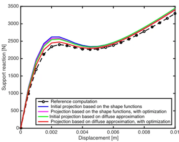
Taken into consideration the projection of the damage field, the damaged cross-section can be included in fiber-beam elements. In this part, a RC beam of length 4.5m is considered. The beam cross-section dimensions are 0.2mx0.4m. The beam is simply supported. It is subject to a prescribed displacement according to the vertical direction and applied at the midspan point. Figure 8summarizes the boundary conditions mentioned. The damaged state of the material is taken as an initial state, before applying the mechanical loading. The beam is discretized using 6 fiber beam elements. A first computation is carried out using the reference fine mesh for the cross-section. Then the cross-section meshed with the coarsest mesh of 156 elements is used. The initial damage distributions considered are obtained by both proposed projection methods, without and with optimization of the projection. The results from the beam computations are presented in Figure 9.
Figure 8: Model of the numerically-tested beam Champ obtenu par approximation diffuse
ENDO > 0.00E+00 < 1.00E+00 3.97E−02 8.73E−02 0.13 0.18 0.23 0.28 0.33 0.37 0.42 0.47 0.52 0.56 0.61 0.66 0.71 0.75 0.80 0.85 0.90 0.94 0.99
Champ obtenu par approximation diffuse Lv= 3
ENDO > 0.00E+00 < 1.00E+00 3.97E−02 8.73E−02 0.13 0.18 0.23 0.28 0.33 0.37 0.42 0.47 0.52 0.56 0.61 0.66 0.71 0.75 0.80 0.85 0.90 0.94 0.99
Champ obtenu par approximation diffuse
ENDO > 0.00E+00 < 1.00E+00 3.97E−02 8.73E−02 0.13 0.18 0.23 0.28 0.33 0.37 0.42 0.47 0.52 0.56 0.61 0.66 0.71 0.75 0.80 0.85 0.90 0.94 0.99
Champ obtenu par approximation diffuse
ENDO > 0.00E+00 < 1.00E+00 3.97E−02 8.73E−02 0.13 0.18 0.23 0.28 0.33 0.37 0.42 0.47 0.52 0.56 0.61 0.66 0.71 0.75 0.80 0.85 0.90 0.94 0.99
Champ obtenu par approximation diffuse optimisé
ENDO > 0.00E+00 < 1.00E+00 3.97E−02 8.73E−02 0.13 0.18 0.23 0.28 0.33 0.37 0.42 0.47 0.52 0.56 0.61 0.66 0.71 0.75 0.80 0.85 0.90 0.94 0.99
Champ obtenu par approximation diffuse optimisé Lv= 3
ENDO > 0.00E+00 < 1.00E+00 3.97E−02 8.73E−02 0.13 0.18 0.23 0.28 0.33 0.37 0.42 0.47 0.52 0.56 0.61 0.66 0.71 0.75 0.80 0.85 0.90 0.94 0.99
Champ obtenu par approximation diffuse optimisé
ENDO > 0.00E+00 < 1.00E+00 3.97E−02 8.73E−02 0.13 0.18 0.23 0.28 0.33 0.37 0.42 0.47 0.52 0.56 0.61 0.66 0.71 0.75 0.80 0.85 0.90 0.94 0.99
Champ obtenu par approximation diffuse
ENDO > 0.00E+00 < 1.00E+00 3.97E−02 8.73E−02 0.13 0.18 0.23 0.28 0.33 0.37 0.42 0.47 0.52 0.56 0.61 0.66 0.71 0.75 0.80 0.85 0.90 0.94 0.99
7
Figure 9: Results of the fiber-beam elements computation.
The quality of the results of the three-point bending computation is satisfactory when comparing with the projection methods at the cross-section scale. The projection based upon diffuse approximation with optimization of the damage distribution leads to a behavior close to the reference curve. This result confirms the choice of the projection method that will be used for further computations.
CONCLUSIONS AND FURTHER WORK
The objective of the study reported in this paper was to develop an efficient computational model of RC members. A model to account for the rebar swelling due to corrosion in a fiber beam element model has been presented. It consists in first computing the concrete damage due to the rebar expansion in a plane cross section. Then, the damage distribution is projected on a coarser mesh, which will be used for the dynamic computation of the structure behavior. Two projection methods have been investigated. The first projection method is based upon the use of the shape functions. This method quickly reaches its limits when the mesh size is increased. An optimization procedure, based upon the cross-section stiffness matrix, has been proposed. The optimization improves the results of the projection method, but does not enable the use of a mesh coarse enough to be included in fiber-beam elements for a dynamic computation. Thus, a second projection procedure is investigated, based upon diffuse approximation. Combined with the proposed optimization, this method leads to satisfying results at the cross-section scale. The projected damage fields have been used to compute the non-linear force-displacement response of a RC beam subjected to three-point bending loading. The results confirmed the relevancy of the projection method selected.
Corrosion also induces a loss of the steel/concrete bond strength. This sliding phenomenon cannot be taken into account with a classical beam element formulation, because the plane cross-section kinematics enforces a perfect bond between the two materials. The cross-section kinematics thus needs to be enhanced, to allow a displacement jump between the concrete part of the section and the steel rebars.
The numerical model relies on an experimental study conducted on large-scale RC beams [19]. The corroded specimens, at different corrosion rates, will be subjected to quasi-static and dynamic loadings. The objective of the experimental campaign is to estimate the evolution of dynamic properties (mode shapes, natural frequencies, energy dissipation…) as a function of corrosion rate. When the experimental results will be available, they will be used as reference data to validate the results of the enhanced numerical model.
ACKNOWLEDGMENTS
The authors gratefully acknowledge the IRSN for the financial support of this work.
REFERENCES
[1] S. Grange, P. Kotronis and Mazars, Jacky, " Numerical modelling of the seismic behaviour of a 7-story building: NEES benchmark.," Materials and Structures, vol. 42, no. 10, pp. 1433-1442, 2008.
[2] P. Kotronis and S. Grange, " Simplified modelling strategies for reinforced concrete structures.," European Journal of
Environmental and Civil Engineering, vol. 14, no. 6-7, pp. 823-838, 2010.
0 0.002 0.004 0.006 0.008 0.01 Displacement [m] 0 500 1000 1500 2000 2500 3000 3500 Support reaction [N] Reference computation
Initial projection based on the shape functions Projection based on the shape functions, with optimization Initial projection based on diffuse approximation Projection based on diffuse approximation, with optimization
12th Canadian Conference on Earthquake Engineering, Quebec City, June 17-20, 2019
8
[3] P. Kotronis and J. Mazars, " Simplified modelling strategies to simulate the dynamic behaviour of r/c walls.," Journal of
Earthquake Engineering, vol. 9, no. 2, pp. 285-306, 2005.
[4] D. L., R. F., M. J. and I. A, "Efficient Approaches to Finite Element Analysis in Earthquake Engineering," Computers &
Structures, vol. 81, no. 12, pp. 1223-1239, 2003.
[5] R. B., R. F., A. L and C. Ch, "A multi-fiber approach for modelling corroded reinforced concrete structures," European
Journal of Mechanics A/Solids, vol. 30, pp. 950-961, 2011.
[6] A. Bérard, "Transferts de champs entre maillages de type éléments finis et applications numériques en mécanique non linéaire des structures," Thèse de doctorat. Université de Franche-Comté, 2011.
[7] D. Brancherie, P. Villon and A. Ibrahimbegovic, "On a consistent field transfer in non linear inelastic analysis and ultimate load computation," Computational Mechanics, vol. 42, no. 2, pp. 213-226, 2008.
[8] J. Mazars, "A description of micro-and macroscale damage of concrete structures.," Engineering Fracture Mechanics,, vol. 25, no. 5, p. 729–737, 1986.
[9] J. Chiles, "Quelques méthodes de simulation de fonctions aléatoires intrinsèques.," Cahiers de Géostatistique, vol. 5, pp. 97-112, 1995.
[10] B. Richard, F. Ragueneau, C. Cremona, L. Adelaide and J. L. Tailhan, "A three-dimensional steel/concrete interface model including corrosion effects," Engineering Fracture Mechanics, vol. 77, no. 6, pp. 951-973, 2010.
[11] G. Duffó, W. Morris, I. Raspini and C. Saragovi, "A study of steel rebars embedded in concrete during 65 years,"
Corrosion science, vol. 46, no. 9, p. 2143–2157, 2004.
[12] K. K. Aligizaki, M. R. de Rooij and D. D. Macdonald, "Analysis of iron oxides accumulating at the interface between aggregates and cement paste.," Cement and Concrete Research, vol. 30, no. 12, p. 1941–1945, 2000.
[13] R. M. Cornell and U. Schwertmann, he iron oxides: structure, properties, reactions, occurrences and uses., John Wiley & Sons, 2003.
[14] T. D. Marcotte, "Characterization of chloride-induced corrosion products that form in steel-reinforced cementitious materials," PhD Thesis, University of Waterloo, 2001.
[15] W. J. Chitty, P. Dillmann, V. L’Hostis and C. & Lombard, "Long-term corrosion resistance of metallic reinforcements in concrete - a study of corrosion mechanisms based on archaeological artefacts.," Corrosion Science, vol. 47, no. 6, pp. 1555-1581, 2005.
[16] Q. T. Nguyen, S. Caré, Y. Berthaud and A. Millard, "Fissuration du béton soumis à la corrosion.," L'objet , vol. 8, 2005. [17] A. Millard, "Castem 2000 User Manual," Rapport CEA-LAMBS No 93/007, Commissariat Francais Energie Atomique,
Saclay, France, 1993.
[18] B. Richard, G. Rastiello, C. Giry, F. Riccardi, R. Paredes, E. Zafati and C. ... & Lejouad, "CastLab: an object-oriented finite element toolbox within the Matlab environment for educational and research purposes in computational solid mechanics," Advances in Engineering Software, vol. 128, no. 136-151.
[19] C. Lejouad, B. Richard, P. Mongabure, S. Capdevielle and R. F, "Assessment of the seismic behaviour of corroded RC beams: an experimental contribution," in submitted to CCEE 2019, Quebec, 2019.