HAL Id: cea-01873010
https://hal-cea.archives-ouvertes.fr/cea-01873010
Submitted on 12 Sep 2018
HAL is a multi-disciplinary open access archive for the deposit and dissemination of sci-entific research documents, whether they are pub-lished or not. The documents may come from teaching and research institutions in France or abroad, or from public or private research centers.
L’archive ouverte pluridisciplinaire HAL, est destinée au dépôt et à la diffusion de documents scientifiques de niveau recherche, publiés ou non, émanant des établissements d’enseignement et de recherche français ou étrangers, des laboratoires publics ou privés.
Compact Neutron Sources for Neutron Scattering
Frédéric Ott
To cite this version:
Frédéric Ott. Compact Neutron Sources for Neutron Scattering. [Technical Report] CEA Paris Saclay. 2018. �cea-01873010�
1
Version 0.6, February 12th 2018
Compact Neutron
Sources for Neutron
Scattering
2
Table des matières
1 Introduction ... 3
2 Performances of Compact Accelerator-driven Neutron Sources (CANS) ... 4
2.1 What do we mean when we talk about a compact accelerator-driven neutron source? ... 4
2.2 State of the art ... 4
2.2.1 The LENS compact neutron source ... 5
2.2.2 The RANS compact neutron source... 5
2.2.3 The HUNS source (Hokkaido University) ... 6
2.2.4 The CPHS source ... 7
2.3 Advantages / drawbacks of a CANS ... 8
2.3.1 Advantages ... 8
2.3.2 Drawbacks ... 8
2.4 Technological boundaries ... 8
2.4.1 Accelerator technology ... 8
2.4.2 Engineering technology ... 9
2.5 Expected performances for neutron scattering on a high brilliance CANS ... 13
2.5.1 European designs ... 13
2.5.2 Target-Moderator- Reflector design and brilliance ... 14
2.5.3 Performances of neutron scattering spectrometers on a compact neutron source .... 15
2.6 Costs of a High Brilliance CANS ... 17
2.6.1 Costs at existing neutron scattering facilities ... 17
2.6.2 Costs of existing CANS ... 17
2.6.3 Costs of a High Brilliance CANS ... 17
3 A CANS for France? ... 19
3.1 Neutrons in the 21st century... 19
3.2 Landscape in France ... 19
3.3 Assets of France in neutron scattering ... 21
4 Other opportunities ... 23
4.1.1 Industrial radiography station ... 23
4.1.2 Production of radio-isotopes ... 23
4.1.3 Measurement of nuclear cross-sections ... 23
5 Conclusion ... 24
3
1 Introduction
As soon as neutron reactors were operating they have been used for neutron scattering experiments. Once the potential of neutron scattering was unraveled for magnetic studies and spectroscopic measurements dedicated facilities were built. The still world leading facility, the Institut Laue Langevin, started operation as early as 1971. It is still operating the most performing instruments nowadays. There are currently about 50 nuclear research reactors operating across the world who are performing neutron scattering experiments [1]. Among these facilities, 20 are running a user program, that is, they are offering the possibility to academic users to perform neutron scattering experiments. During the 1980’, a new type of neutron facilities based on the spallation reaction were developed. Eventually this led to the creation of 3 new facilities (KENS in Japan, IPNS [2], Los Alamos Neutron Science Center [3] and ISIS [4]) which were also running a user program. During the 2000’, a second generation of spallation sources was built (SNS in the USA [5] and JPARC in Japan [6]). ESS [7] which can be considered as a third generation spallation source is currently being built in Europe.
These last sources are very powerful and are able to replace or overtake nuclear reactors in terms of performances for neutron scattering. Considering the political situation in Europe, it is very unlikely that new nuclear research reactors will be built in replacement of the old ones. However, currently aging facilities are providing a broad user base to the most performing ones. It is thus necessary to try to find a solution to ensure that the broad user base (6000 users [8]) can be maintained in Europe in order to make the best use of the most powerful sources. The price tag of a full fledge spallation source is quite high (~1B€) and is difficult to bare by a single country. Hence any possibility to build neutron scattering facilities which could replace existing nuclear reactors would be welcome provided the investment is in the 100M€ range which would make it affordable to a single country on par with a synchrotron or a power laser facility.
The Figure 2 shows the raw
neutron production in
neutron/s/mA for various incident particle energies on various targets. During the last decade a number of groups have independently considered the possibility of operating a high current / low energy proton accelerator to produce thermal and cold neutrons [9-10-11-12-13-14]. A few facilities have actually been built and are
operating scattering
instruments [15]. A UCANS network gathering these groups has been created [16]. The core
idea of these projects is that low energy accelerator source if properly optimized for a well identified task can provide neutron flux suitable for a number of experiments.
4
2 Performances of Compact Accelerator-driven Neutron
Sources (CANS)
2.1 What do we mean when we talk about a compact accelerator-driven
neutron source?
An accelerator-driven neutrons source is composed of the following elements:
A proton or deuton source producing a particle beam at energies on the order of 100 keV with a peak intensity up to 100mA
A RFQ stage (Radio-Frequency Quadrupole) whose role is to shape the continuous ion beam and ensure a first acceleration up to an energy of a few MeV
Extra accelerating stages to push the ion energies to the requested energy (several 10 MeV) Transport lines to the target.
A target made of a material generating neutrons when interacting with protons
A moderator and a reflector whose role is to slow down the neutrons down to the energy requested by the final users (typ. 2 à 100 meV).
Several neutron beam lines bringing the neutrons to the spectrometers.
While on a reactor the number of produced neutron is in the range of 1018 n/s, the actual neutron flux
on a sample is on the order of 107 n/s. That is only a fraction on the order of 10-11 of the produced
neutrons is actually used for scattering. This leads to side effects such as massive shielding requirements.
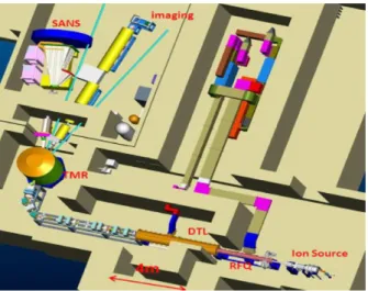
In CANS, the term “Compact” refers to the Target Moderator Assembly (TMR) which can be made very small (a few liters) compared to reactor reflector vessels whose volume is in the 1m3 range. Hence
while the raw number of neutron produced on a CANS can be small, a high brilliance of the source can be obtained in the small TMR volume. Only useful neutrons are produced.
The whole philosophy of compact neutron source designs is “produce what you need”.
The whole source is also physically compact (10-30m long) compared to spallation facilities (600m long) which are operating at high proton energies (~1 GeV).
2.2 State of the art
Accelerator based neutron sources do exist since several decades but they have been mostly based on photo-fission neutrons produced with electron beams. This is historically due to the fact that electron accelerators are significantly easier to build than proton accelerators. The Harwell facility used an electron linac to produce neutrons with a uranium target as early as 1967 and performed neutron scattering experiments [17]. Facilities such as HUNS in Japan or the Bariloche LINAC in Argentina also started operation during the 1970’ and are still working. They have mostly focused on nuclear physics experiments.
During the last 20 years significant developments have been made in the field of accelerators and the possibility of operating accelerators with ion currents on the order of 100mA have been demonstrated. About 15 years ago this has led to an interest in setting up neutron sources based on proton
5
accelerators for neutron scattering. In 2009, the UCANS Union for Compact Accelerator Neutron Source has been created (http://www.ucans.org/). Three documented facilities are described below.
2.2.1 The LENS compact neutron source
The LENS facility is based at the Bloomington University Indiana. The nominal parameters are 13MeV, Ipeak = 20mA, duty cycle ~1%. It is operating a SANS instruments, a Spin-Echo instrument, and a
radiography instrument. Some SANS data show that it is possible to measure SANS signal down to 0.1cm-1 (Das et al, Langmuir 2014) which is only 10 times higher than measurements at regular SANS
machines on existing user facilities.
Figure 2: (left) LENS layout with 2 target stations (green) and 3 instruments around the 2nd target station. (right) SANS data. CTAB (200mM) micelles with 120 mM NaCl. Measured at LENS@13MeV; 20mA; 20Hz, 600µs; Iav = 0.24mA ; P = 3kW (Das et
al, Langmuir 2014).
2.2.2 The RANS compact neutron source
The RANS source at Rikken in Japan does not (yet) operate dedicated instruments but performs experiments “on demand”. Simple “instruments” are set-up around the source as needed. The source operates at Ep = 7 MeV ; Iav = 100µA ; Pmax = 700W.
6
Figure 4: Powder diffraction patterns on steel samples providing the austenite – martensite ratios.
Figure 5: Radiography of corroded steel plates and humidity up-take as a function of time. Pixel Size 0.8x0.8mm² ; 5 minutes exposure time; Ep = 7 MeV ; Iav = 15µA ; P = 100W.
2.2.3 The HUNS source (Hokkaido University)
Hokkaido University neutron source, HUNS was completed in 1973, and has been used actively for developments of moderators, neutron instruments, neutron devices and new methods for 40 years although its power is not so high. Recently, a pulsed neutron imaging method has been developed and a new type of small angle neutron scattering method has been also tested.
7
Figure 6: (left) SANS in steel samples with (filled markers) and without (open markers) nanoscopic precipitates. (right) Bragg-edge transmission spectra measured at HUNS, and the profile fitting curves obtained by RITS. [18]
2.2.4 The CPHS source
China is putting huge efforts in neutron scattering: the 60 MW CARR reactor, the China Spallation Neutron Source (CSNS), the 20 MW China Mianyang Research Reactor (CMRR) are all designed to be user facilities. Besides, the CPHS is a less ambitious project of a compact source based in Beijing. The parameters of the source are Ep = 13MeV, Ipeak = 50mA, duty cycle = 2.5%, P = 16.3kW. It is however
not yet operating at the nominal proton energy of 13 MeV but is limited at Ep = 3MeV.
8
Figure 8: the MCP image of a USAF-1951 Gd-mask measured with the beam line of CPHS at 3MeV (left) and CARR (right). Note that the measuring conditions are not documented (measuring time, L/D ratio, CARR power…)
2.3 Advantages / drawbacks of a CANS
2.3.1 Advantages
- Low energy protons (10MeV versus 1GeV) o « Light » shielding (20 tons Vs 6000 tons)
- The instrument line starts from the inside of the moderator - Less high energy neutrons (less secondary background) - Reduced costs
o Accelerator of 20m versus 600m at ESS
- a CANS is not a nuclear facility (Installation Nucléaire de Base)
2.3.2 Drawbacks
- The flux is intrinsically limited by the peak current (Ipeak ~ 100mA)
2.4 Technological boundaries
The above sources have been setup with very limited resources and are not operating at the state of the art accelerator technological limits. For example LENS was built around an old refurbished proton accelerator. RANS was built around a low peak current second hand proton accelerator. CPHS is built around a “home” made accelerator by a university willing to master accelerator technology. Hence these projects do not reflect the nowadays potential state of the art.
2.4.1 Accelerator technology
The first technical limit is set by the peak proton current which can be achieved. The peak current is about 100mA to ensure a reliable operation. In the ESS design (10 years old) the peak current was set to a safe value of 60mA. New facilities such as IFMIF are aiming for 125 mA currents.
Accelerators can operate in continuous mode or in pulsed mode. For neutron scattering the most efficient operation is in pulsed mode to benefit from the time-of-flight techniques. Most spallation sources are nowadays operating in pulsed mode.
9
The choice of the ion particle is still under debate. Protons are significantly easier to handle than deutons and also they do not induce activation issues in the accelerator parts as deutons do. The nuclear data are very scarce in the 3-60MeV range and the cross sections are poorly known. Some models suggest that deutons might be more efficient than protons, others not. Some experimental work is under way to fill the database gap in the energy range of interest (P. Zakalek, JCNS).
2.4.2 Engineering technology
The choice of the target material is non-trivial and would require extensive discussion. The situation can be roughly summarized as follows:
For proton energies below 3MeV, Lithium should be preferred due to the low stripping reaction threshold. This is the choice made for low energy Boron Neutron Capture Therapy accelerators for example.
For proton energies in the range 3MeV- 60MeV; Beryllium and Lithium are roughly equivalent in terms of neutron yield; However using significant power levels (kW) on the target will require to handle molten lithium which is challenging but is justified for very high power since it makes the cooling more efficient (see IFMIF@5MW). Beryllium on the other hand has a very high melting point (1287°C) and allows operating a solid target up to energy densities in the range 0.5-1 kW/cm².
From 60-100 MeV, there are several candidate materials (among which carbon for example). Again the lack of nuclear data makes choices non trivial.
Above 100MeV, the neutron production via spallation channels starts being efficient and a heavy material target becomes the best choice (e.g. Tantalum)
A key choice in a facility design is thus the choice of the proton energy. This choice must be weighted by different factors: (i) the neutron yield, (ii) the accelerator cost, (iii) the power deposited on the target.
For CANS, within the institutes working on the topic, a consensus seems to have been reached towards a Beryllium target. The ion choice (proton Vs deuton) still has to be settled. The ion energy range is between 10 to 50MeV.
The figure below shows the neutron yield of a beryllium target Vs the proton energy. There is a threshold of 2 MeV for neutron production and above 20MeV the yield is roughly linear with the proton energy with a slope: Yield = 4 x Ep.
10
Figure 9: Neutron yield as a function of the proton energy on beryllium target.
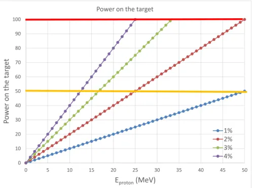
The design of an efficient TMR requires that the target is as small as possible. A typical (maximum) size is on the order of 100cm². Thermo-hydraulics requires that the maximum power density is in the range 0.5-1 kW/cm² which sets a limit of the ion beam energy at 50-100 kW. The figure below shows the power deposited on the target as a function of the proton energy. The orange line at P= 50 kW corresponds to a “safe” limit where thermo-hydraulics design are not challenging. The limit at P=100 kW is probably a hard limit above which a fixed target cannot be used and a rotating target is necessary. The different load lines correspond to increasing duty cycle of the source. As a reference, the long pulse source ESS is operating with 2.86ms pulses at 14 Hz corresponding to a duty cycle of 4%. In this operation scenario, the maximum proton energy which can be used is about 20-25MeV. If the proton energy is increased to 50 MeV, the duty cycle has to be reduced to 2%. Hence while the neutron yield increases with the proton energy, the duty cycle has to be decreased to limit the power on the target. Thus the gain in flux are roughly linear with the proton energy.
For Ep = 20 MeV – Ipeak 100mA – 4% duty cycle – P = 80kW: Yield = 3.1x10¹⁴ n/s
For Ep = 40 MeV – Ipeak 100mA – 2% duty cycle – P = 80kW: Yield = 5.4x10¹⁴ n/s
It is difficult to define a simple figure of merit since a number of “soft” parameters also play a role. - What is the most suitable duty cycle? This depends on the aimed applications
- For lower energy protons, the fast neutron spectrum is less energetic and thus easier to moderate. - The gamma background is also less energetic for lower energy protons
- A lower energy accelerator is cheaper to build
- Above Ep = 30MeV, new activation channels open and lead to activation of accelerators parts which
can make the maintenance more complicated.
Solutions in the range 13Mev – 50MeV should be considered using various duty cycles. 0E+00 5E+13 1E+14 2E+14 2E+14 3E+14 3E+14 4E+14 4E+14 0 10 20 30 40 50 N e u tro n s / m A Eprotons(MeV)
11
Figure 10: Power on the target for increasing proton energy and various duty cycles.
0 10 20 30 40 50 60 70 80 90 100 0 5 10 15 20 25 30 35 40 45 50 Po w er on the t ar ge t Eproton(MeV)
Power on the target
1% 2% 3% 4% 0 2 4 6 8 10 12 14 16 0E+00 5E+13 1E+14 2E+14 2E+14 3E+14 3E+14 4E+14 4E+14 0 10 20 30 40 50
I
aver ag e(m
A)
Fa
st
N
eut
ron
s
/mA
E
protons(MeV)
n/s/mA
Iaverage (P = 50kW)
12
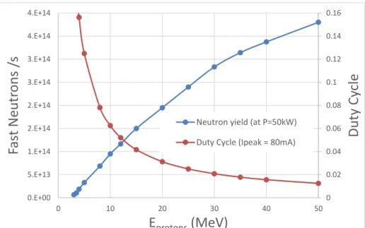
Figure 11: (a) Neutron yield /mA versus proton energy and maximum average current to limit the power on the target at 50kW. (b) Actual yield with a power limit on the target set at 50kW and corresponding duty cycle (for Ipeak = 80mA). While the
neutron yield per proton doubles from Ep = 20 to 30 MeV, power limits on the target reduce the gain to 45%. In parallel, the
duty cycle on the target is reduced (from 3% to 2% if Ipeak = 80mA) which makes the neutron pulses easier to exploit for
scattering experiments. From 20MeV to 30MeV the gain in flux is proportional to the accelerator cost. From 30MeV to 50MeV, the gain in flux is 36% while the proton energy is increased by 67%.
Assuming that the accelerator cost and operation is proportional to its energy (which is rather crude), a simple figure of merit could be defined as FOM = Neutrons / Eprotons (see figure below). It is clearly
efficient to work above 10 MeV. However, even though the neutron yield / proton increases quickly with the proton energy, the figure of merit nevertheless decreases slowly above 20 MeV.
Figure 12: Figure of merit defined as Flux / Cost (a.u.)
0 0.02 0.04 0.06 0.08 0.1 0.12 0.14 0.16 0.E+00 5.E+13 1.E+14 2.E+14 2.E+14 3.E+14 3.E+14 4.E+14 4.E+14 0 10 20 30 40 50
Dut
y Cy
cle
Fas
t Neut
rons
/s
E
protons(MeV)
Neutron yield (at P=50kW) Duty Cycle (Ipeak = 80mA)
0 0.2 0.4 0.6 0.8 1 1.2 0 10 20 30 40 50
Fig
ur
e
of M
er
it
E
protons(MeV)
13
2.5 Expected performances for neutron scattering on a high brilliance CANS
In Europe several institutes are considering high end CANS facilities using the latest available technologies to achieve High Brilliance using low energy accelerators.
2.5.1 European designs
2.5.1.1 The ESS-B reference design
The ESS-Bilbao institute is in charge of the Spanish contribution to the ESS construction. It has put together a detailed technical design study of a CANS design which could provide neutrons as a user facility [19]. The reference design is based on a 50 MeV proton accelerator and a power on the target of 115 kW. It will be using a rotating Beryllium target.
2.5.1.2 The HBS reference design
The Jülich Center for Neutron Scattering at the Forschung Zentrum Jülich is considering the design of a High Brilliance Source with the following parameters, Ep = 50MeV, Ipeak = 100mA, P = 100kW, fixed Be
target [11].
2.5.1.3 The NOVA-ERA reference design
The Jülich Center for Neutron Scattering at the Forschung Zentrum Jülich is also considering the construction of a “laboratory” source with modest performances NOVA-ERA Neutrons Obtained Via Accelerator for Education and Research Activities.
The design parameters are Ep = 10MeV, Ipeak = 1mA, P = 1kW, Be target, duty cycle 4-10%. Such a source
can be built using off-the-shelf commercial proton accelerators. The source will be shared between ion physics and neutron physics (5 + 5 instruments).
2.5.1.4 The SONATE reference design
The CEA is considering a reference design SONATE with the following parameters: Ep = 20MeV, Ipeak = 100mA, duty cycle = 4%, P = 80kW, fixed Be target.
These parameters were chosen partly because they correspond to the first 20m of the ESS Linac (out of 600m). Hence the components (Source, RFQ and DTL) are available with no R&D developments.
2.5.1.5 The LENOS design
The LNL Laboratori Nazionali di Legnaro is commissioning the LENOS facility (LEgnaro NeutrOn Source facility). The design parameters are Ep = 70 MeV, Iav = 750 µA, Lithium target. This facility is close to
completion but is not oriented towards neutron scattering but rather towards nuclear physics.
2.5.1.6 The LvB design
The KFKI has started to build a low energy CANS (Ludwig van Beethoven) which will use a low energy accelerator (3MeV).
2.5.1.7 Facilities outside Europe
A number of projects are on-going across the world.
In Japan, the HUNS facility using photo-fission has operated for 40 years. RANS (Rikken) and KUANS (Kyoto University) are operating at 350 and 700 W. The iBCNT (Ibaraki prefecture) and the NUANS (Nagoya University) facilities are close to completion and aim to operate in the 50kW range. Other projects are under construction or under consideration (QUANS, THUANS, UTYANS, OUANS).
14
Israel. Its design parameters are: Ep = 40 MeV, Iav = 5mA CW, P = 200 kW. The source is under
construction and is designed to operate as a multipurpose source: nuclear physics, radiography, radio-isotopes, neutron based therapy, material testing.
In China, CPHS in Beijing has produced neutrons and should eventually upgrade to 13MeV / 16kW. PKUNIFTY (Peking University) (Ep = 2MeV; 1kW) is performing neutron radiography.
In the USA, SNS has set-up a CANS for its moderator developments for the second target station.
2.5.2 Target-Moderator- Reflector design and brilliance
The performances of TMR assemblies can be estimated via Monte-Carlo simulations using MCNP or GEANT4 for example. The figure below shows an example of a TMR assembly consisting of a V-shape Beryllium target (red), in a 17cm diameter poly-ethylene sphere (~2 liters) acting as a thermal moderator.
An important aspects is that the extraction channels represent a very small fraction of the solid angle around the PE sphere and the channel presence is perturbing the flux only in the 5-10% range. Hence one can consider that a TMR assembly can easily accommodate 5 instrument lines.
Figure 13: (Left) moderator geometry (red) wedge target, (green) poly-ethylene thermal moderator, (yellow) Beryllium reflector. In 2 extraction tubes, a para-H2 cold moderator (orange) and a CH4 cold moderator are inserted. (Right) Flux at the
exit of the moderator channels with < 1°. (Jan Philip Dabrück, Univ. Aachen).
The Monte-Carlo simulations were experimentally checked by measurements on a poly-ethylene (PE) moderator set around a Beryllium target on the IPHI accelerator operating at 3 MeV. These measurements shows that the Monte-Carlo simulations are quite reliable, within 20-30% at the exit of the moderator.
15
Figure 14: (Left) Simple PE moderator set around a Be target on the IPHI accelerator in Saclay. (right) (solid lines) Monte Carlo simulations with 2 different physics model in GEANT 4 and (black dots) gold disks neutron flux measurements.
2.5.3 Performances of neutron scattering spectrometers on a compact neutron source
A simple moderator geometry was chosen and its brilliance was calculated. In the case of the SONATE design, a brilliance of 1.2x10¹¹ n/cm²/s/sr was calculated and was used as an input in the instrument
Monte-Carlo simulations (using McSTAS).
The neutron flux at the sample position for various neutron scattering techniques are summarized in the table below and compared with “reference” instruments at sources such as Orphée or ISIS. The figures for the inelastic instruments (Direct TOF and Inverse TOF) have been provided by Jörg Voigt from JCNS.
Technique Flux on sample Reference spectrometers Potential gains Reflectivity 0.8x10⁷n/s/cm² HERMES@LLB 1x10⁷ n/s/cm² POLREF@ISIS ~1x10⁷n/s/cm² ESTIA@ESS concept x10 Advanced Deconvolution x3 SANS 0.7x10⁶n/s/cm² (low Q) 2.2x10⁶n/s/cm² (med Q) 6.7x10⁶n/s/cm² (high Q) PAXY@LLB (low Q) 0.7x10⁶ n/s/cm² SANS2D@ISIS 1x10⁶n/s/cm² Slit setup x10
Focusing optics for VSANS (small Q) x10
Powder diffraction
2x10⁶n/s/cm² G41@LLB 2x10⁶ n/s/cm² Large solid angle detector (7C2 type) x20 Imaging (white beam) 1.5x10⁶n/s/cm² (for L/D = 240) 1.3x10⁷n/s/cm² (for L/D = 80) ICON@PSI 1x10⁷n/s/cm² CONRAD@HZB 1x10⁷n/s/cm² (for L/D = 240) MCP detectors x5
Coded Source Imaging x10
Imaging (time resolved)
1x10⁵n/s/cm² (for L/D = 500) dl/l = 1%
ANTARES@FRM2 5x10⁵n/s/cm²
Direct TOF 3x10⁴n/s/cm² (thermal)
1.8x10⁵n/s/cm² (cold) IN5@ILL 6.8x10⁵n/cm²/s
MUSHROOM (LETx70 on single crystals)
Inverse TOF 1x10⁷n/cm²/s OSIRIS@ISIS 2.7x10⁷n/cm²/s
16
Figure 15: Comparison of the performances of different scattering techniques in terms of flux at the sample position (n/cm²/s). (red) reference instruments at various facilities (LLB – ISIS – ILL) ; (blue) move of the existing instruments from Orphée to SONATE ; (green) performances after technical upgrades. The figures for the inelastic instruments (Direct TOF and Inverse TOF) have been provided by Jörg Voigt from JCNS.
While these simulations rely on Monte-Carlo simulation of a model moderator, the performances loss during the engineering phase are likely to be offset by moderator geometry optimization. The ESS moderator geometry optimization led to gains of a factor 3 in the ESS brilliance between the ESS TDR 2012 and the final design (see below).
Figure 16: Increase of the ESS moderator brilliance between the ESS 2012 TDR (grey) and the final design (blue). A further gain is expected by using tube moderators.
The conclusion which can be drawn from these simulations is that a High Brilliance CANS (Source à Haute Brilliance, SHB) can offer performances in the range of medium flux reactors or low power spallation sources.
10000 100000 1000000 10000000 100000000
Spin-Echo Inverse TOF Direct TOF Imaging (energy resolved) Imaging (white beam) Powder diffraction SANS Reflectivity
17
2.6 Costs of a High Brilliance CANS
2.6.1 Costs at existing neutron scattering facilities
The figures quoted in this section are issued from the ESFRI Report on “Neutron scattering facilities in Europe, Present status and future perspectives (2016)”.
Facility ILL ISIS MLZ SINQ ESS LLB
First Neutrons 1971 1994 2004 1998 2023 1981 Replacement value (M€) 2000 800 600 750 1847 400 Operating costs (M€) 95 62 55 30 140 30 Instrument-day (k€) 11.9 16.7 9.2 12.5 35.3 7.9 Operation cost / replacement value 4.75% 7.75% 9.2% 4% 7.6% 6.7%
(*) The cost per instrument-day is defined as the operational costs / instrument.days. The capital investment is not included.
2.6.2 Costs of existing CANS
It is very difficult to assess costs for Compact Neutrons Source since only very few facilities have been built. Besides a number of facilities have been built using existing infrastructure to minimize the costs and none of the existing facilities are operating as “user facilities”.
The CPHS facility in Beijing was built from scratch and has rather ambitious goals (Ep = 13MeV; 16kW).
The claimed costs are about 13M€. Note that the situation in China can hardly be compared with the situation in Europe in particular in terms of manpower costs.
The LENS source in the USA benefited from existing infrastructures (building + accelerator) so that the total costs cannot be estimated reliably. The claimed operation costs are very low though (200k$) (excluding manpower). The cost of a “LENS class” source (13MeV, 30kW) is quoted as M$20 (D. Baxter, IAEA Report1) (not including neutron scattering instrumentation).
The RANS source in Rikken was built using some second parts also. No “global” figures could be found.
2.6.3 Costs of a High Brilliance CANS
The investment cost for a high brilliance neutron source with a beam power of 100 kW and a proton energy in the range 20-30 MeV was estimated in the range of 50M$ (IAEA Report1).
It is possible to project the cost from the current facilities being built in Europe. The cost of the ESS LINAC sections up to 20 MeV as well as the cost of elements for the IFMIF facility leads to an accelerator cost of 28M€. The cost of 2 target stations can be estimated to be in the 5M€ range. Building and
18
overheads of about 20% in engineering and management should be added. This leads to a total cost for the source construction (without instruments) of 46M€. This figure is very close to the IAEA earlier estimate.
Commercial linacs are also available. The PL-11 model from AccSys provides 11MeV protons with a 40mA peak current and an average current of 1mA, corresponding to a duty cycle of 2.6%. The power of such an accelerator is on the order of 10 kW on the target and the price tag for the system is about 4M€. The system is sold as a turn-key system which minimizes the operation costs. Other companies such as IonLinacs claim that they can provide accelerators with very high capabilities (Iav = 30mA, CW,
19
3 A CANS for France?
3.1 Neutrons in the 21
stcentury
At the beginning of the 21st century, neutron scattering has experienced a golden age across the world.
The supply of neutron reached a peak in Europe with more than 35000 instrument.days available per year. However a number of neutron producing reactors are being phased out or will be phased out in the coming decades. So while high end spallation facilities have been built across the world (SNS in the USA, JPARC in Japan) or are being built (CSNS in China, ESS in Europe), there is a risk that these facilities become isolated in the future as aging reactors close down.
CANS offer an opportunity to change the way neutron scattering techniques are used. The flexibility of CANS designs allows optimizing the source for specific needs. The cost of the source can be tuned to match the ambition of the project. A small 10M€ source is accessible to a University (e.g. CPHS, PKUNIFTY, NOVA-ERA), a 50M€ source can replace a medium flux reactor, a 200 M€ source may feature dozens of instruments and be used as a national user facility.
The implementation of CANS has the potential of turning neutron scattering into a more mainstream technique by lowering the entry ticket (investment cost), the operation costs, and overcoming regulatory challenges (no need to build a nuclear reactor and easy decommissioning). It has the potential to make neutron scattering accessible to developing countries.
The fact that operation costs of CANS are significantly lower than current operation costs at existing neutron facilities has also the potential to change their use and turn them into a more mainstream materials characterization technique.
3.2 Landscape in France
In the case of France, the projection of the neutron provision for French users is gloomy. The figure below shows the projected neutron capacity offered to French users by 2035. If no action is taken, after the ILL shutdown, the instrument.days offered to the French community will have decreased by 94% with only access to ESS beam time (300 instrument.days). Even if specific actions are taken such as the outsourcing of some instruments (2-3?) at foreign facilities (FRM2 – PSI), this would at best represent an extra capacity of 200-300 instrument.days. A new facility (SNA, Source de Neutron Alternative) typically operating 10 instruments for 180 days per year would enable to maintain the French neutron capacity above 2000 instrument.days per year (which represent only 40% of the present day capacity).
20
Figure 17: Neutron provision for the French community users over the period from 2015 to 2035. If no action is taken, by 2030 the French community could lose 94% of the available capacity and have access only to ESS beam time (300 days/year, green capacity). An Alternative Neutron Source (SNA) with 10 instruments could boost the capacity by an extra 1800 instrument.days. (adapted from [8]).
It could be argued that considering the neutron flux at ESS, the instrument performances are expected to be so much higher compared to current reactor facilities (10-20 times better than ILL instruments, 50-100 times better than LLB instruments) that 300 ESS instrument.days could replace 3000-6000 ILL instrument.days.
Figure 18: Number of papers published in high impact journals using data from leading neutron sources around the world, up to 2014. [Courtesy of ILL: Christian Vettier, Helmut Schober & Bill Stirling]2. The value [instrument.days x neutron flux] is quoted
for each source3.
2 ESFRI Report, Neutron scattering facilities in Europe, Present status and future perspectives.
3 The reference neutron flux is normalized at 1 for the ILL, 0.61 for FRM2, 0.27 for NIST, 0.23 for LLB, 0.11 for
SINQ , 0.09 for Berlin. In the case of pulsed sources such a comparison does not make sense.
0 1000 2000 3000 4000 5000 6000 2014 2017 2020 2023 2026 2029 2032 2035
Da
ys.
Spe
ctr
om
et
er
s
SHARP+SAM+GAPS@ILL PA20@PSI LLB ILL ESS 2014 2017 2020 2023 2026 2029 2032 2035 SHARP+SAM+GAPS@ILL PA20@PSI LLB ILL + CRG@ILL SNA ESS 7400 1300 830 4390 350 380 Instruments.days x flux-94%
21
This is contradicted by the scientific output of current neutron scattering facilities normalized by the raw flux numbers. The LLB scientific output is about 33% of the ILL output (see Figure 18) while the ILL is providing 9 times more [instruments.days x neutron flux]. In the case of SINQ@PSI, the scientific output is about 25% of the ILL while the ILL is providing 20 times more [instrument.days x neutron.flux]. This shows that the scientific output of a source does not scale as the raw neutron flux numbers. The current wisdom is that it scales as [instrument.days.researchers]. Instruments with little local scientific support struggle to exploit the data produced on the instrument.
It might also be argued that a significant number of publications have benefited from measurements at both facilities. Indeed, statistics on various sources4 show that on average a publication requires 2
experimental runs. While this is partly true, its supports the fact that high end facilities (ILL in Europe) need support from smaller facilities to boost their output. This shall be the same for ESS in the future. In order to be able to exploit ESS at its full capability, France will need to have national support and expertise for its users. In the same way as synchrotron facilities are benefiting from the vast community of people doing lab x-ray scattering and XFEL facilities will benefit from the vast community of people doing measurements at synchrotron facilities. ESS will need the input from a vast neutron scattering community to deliver its full potential.
A detailed analysis of this leveraging effect can be found in 5. “[ESS] will not replace all existing facilities
in Europe and in fact the efficient use of ESS will require the other facilities capacity and complementary capability, unique instruments and sample environment in order to sustain the necessary user community.” It is estimated that a standalone ESS would have a productivity of 0.7 compared to the current situation (productivity of 1). ESS supported by an ecosystem of national sources would lead to a productivity of 3 compared to the current situation.
Similar conclusions were drawn in the USA6. The OSTP report concluded “while the SNS is a significant
new opportunity to provide world-leading capability in the US it alone cannot provide the necessary neutron scattering capability.”
3.3 Assets of France in neutron scattering
While the short term prospects are gloomy due to the Orphée reactor closure, the current ecosystem around neutron scattering is very rich in France. A CANS facility could strongly benefit from it to make it a successful platform.
The French assets are the following:
- a large French neutron scattering user base (1500 people) (6000 people in Europe) - a strong local scientific expertise at the LLB and around the ILL
- a know-how for the construction of ToF instruments (via the development of 5 instruments for ESS at the LLB)
- the CEA masters most of the accelerator technologies
- existing up to date neutron scattering instruments (in particular LLB instruments starting from 2020)
4 unpublished
5 Report from the ILL Associates’ Working group on Neutrons in Europe for 2025.
6 The Status and Needs of Major Neutron Scattering Facilities and Instruments in the United States , Office of Science and Technology Policy
22
Besides, France could benefit from all the efforts currently being put into ESS.
- a number of new concepts or ideas or instrumentation have been proposed for ESS
- huge computing efforts are underway for ESS which can be reused out of the box for SONATE - intensive R&D work is being performed in the field of neutron detectors. Once the technology
is mature, lower cost detectors should become available.
After the construction phase of ESS, a huge human capital of neutron experts will be available in Europe. It would be a shame to dilapidate it.
ESS will also have set all the infrastructure for building vast quantities of detectors. This infrastructure could be amortized by providing detectors to third party facilities.
Figure 19: A CANS project could benefit from an excellent existing ecosystem.
Compact
Neutron
Source
Pulsée
Instruments
sts
LLB
instruments
LLB expertise
from ESS
instrument
construction
New
instrument
concepts for
ESS
Detector
developments
for ESS
LLB
scientists
Academic
users
(500 /year at the LLB)Data
processing
MANTID
(ESS, ISIS,
ILL, SNS)
SNA platform
FULLPROF GSAS SASFIT BORNAGAIN BASTILLE …Industrial users
(Dassault,
PyroAlliance)
Users
23
4 Other opportunities
The above discussion has been focused on CANS to provide thermal and cold neutrons for scattering experiments. There are currently 3 possibilities which could be considered to increase the use of a CANS.
4.1 Industrial radiography station
An industrial radiography station G45 is currently operated at the reactor Orphée. It main activity is to perform quality checks on pyrotechnic elements. This technique is used by Dassault, PyroAlliance, Aerospatiale… After the Orphée shutdown, these companies are considering using foreign facilities but this is a non-trivial tasks because (i) pyrotechnic elements follow strict rules for handling in terms of regulations and very few facilities can handle them, (ii) it often involves non civilian pieces of equipment.
The services are currently charged to the companies at a marginal cost which does not include the investment cost (Orphée construction). We might be able to achieve sales revenue of 1.5M€ / year which could contribute to the source operation.
While this could cover a non-negligible part of the operation costs of the source it would also imply setting up a (bulky) radiography station and operate it (presently 3 operators part time). The expertise currently exists at the CEA but the industrial clients have not yet made any decision.
4.2 Production of radio-isotopes
There are currently discussions and market evaluation to assess if the production of radio-isotopes using high current proton beams is competitive against cyclotron production. Part of the high current proton beam of SONATE could be used to produce specific radio-isotopes. This possibility is currently being studied at the CEA but is still in a very early stage.
4.3 Measurement of nuclear cross-sections
There is an interest by the CEA/DEN Direction de l’Energie Nucléaire for the possibilities to perform fine nuclear cross section measurements on moderator and reflector materials. An epithermal beam line could be considered on one of the moderators for this purpose. The precise needs should be properly assessed though. The GELINA facility is Belgium is dedicated to cross sections measurements in the range 10meV – 20MeV and operates as a full scale user facility with 12 experimental stations [20].
24
5 Conclusion
The performances of a high brilliance compact neutron source are potentially equivalent to a medium flux reactor while the cost of a CANS is about à 1/5 of a medium flux reactor. A CANS is not a nuclear facility which simplifies and lowers the costs of operation.
Technologically, all the building bricks are available: (i) high current accelerators, (ii) moderators, (iii) instruments. The target still poses engineering challenges but there is currently several institutes working on the issue.
The current neutron scattering ecosystem is very rich in Europe and offers plenty of opportunities. We think that CANS could provide a disruptive approach to neutron scattering.
We propose that a High Brilliance CANS should be built in France. The overall investment cost for a new user facility able to operate 10 instruments is estimated to be in the M€50 range. Such a facility could provide about 1800 instrument.days to a broad user community with a total annual operation cost on the order of 4 M€.
25
6 References
Some general non-technical publications
Towards Compact Accelerator Driven Neutron sources for Europe.
Thomas Gutberlet, Ulrich Rücker & Thomas Brückel (2017) Neutron News, 28:3, 20-25, DOI:10.1080/10448632.2017.1342486
https://doi.org/10.1080/10448632.2017.1342486
[1] IAEA database; nucleus.iaea.org/RRDB/RR/ReactorSearch.aspx
[2] IPSN Intense Pulsed Neutron Source: www.aai.anl.gov/history/project_pages/ipns.html [3] LANSCE: lansce.lanl.gov/
[4] ISIS: www.isis.stfc.ac.uk/ [5] SNS: neutrons.ornl.gov/sns [6] JPARC: j-parc.jp/index-e.html [7] ESS: europeanspallationsource.se/
[8] ESFRI Report, Neutron scattering facilities in Europe, Present status and future perspectives. [9] C.M. Lavelle et al, NIM A 587 (2008) 324-341. Neutronic design and measured performance of the Low Energy Neutron Source (LENS) target moderator reflector assembly.
[10] S. Halfon, A. Arenshtam, D. Kijel, et al. Appl. Rad. Iso. 106 Special Issue (2015) 57-62.
[11] U. Rücker, T. Cronert, J. Voigt, J.P. Dabruck, P.-E. Doege, J. Ulrich, R. Nabbi, Y. Beßler, M. Butzek, M. Büscher, C. Lange, M. Klaus, T. Gutberlet, and T. Brückel, , Eur. Phys. J. Plus (2016) 131: 19. DOI 10.1140/epjp/i2016-16019-5. The Jülich high-brilliance neutron source project.
[12] X. Wang et al, Physics Procedia 60 (2014) 186-192. Delivery of 3-MeV proton and neutron beams at CPHS: A status report on accelerator and neutron activities at Tsinghua University.
[13] Y. Yamagata, K. Hirota, J. Ju et al. J Radioanal Nucl Chem 305 (3) (2015) 787-794. Development of a neutron generating target for compact neutron sources using low energy proton beams.
[14] F. Sordo et al, Nuclear Instruments and Methods in Physics Research A 707 (2013) 1–8. Neutronic design for ESS-Bilbao neutron source.
[15] www.indiana.edu/~lens/sans.html [16] UCANS, www.ucans.org/facilities.html [17] R.N. Sinclair et al, NIM 117 (1974) 445-454
[18] M. Furusaka et al, Physics Procedia 60 (2014) 167-174. Activity of Hokkaido University Neutron Source, HUNS
[19] ESS-Bilbao, Technical Design Report: ESS-BILBAO Target Station.
[20] GELINA: https://ec.europa.eu/jrc/en/research-facility/linear-electron-accelerator-facility