HAL Id: hal-00613945
https://hal.archives-ouvertes.fr/hal-00613945
Submitted on 19 May 2021
HAL is a multi-disciplinary open access
archive for the deposit and dissemination of
sci-entific research documents, whether they are
pub-lished or not. The documents may come from
teaching and research institutions in France or
abroad, or from public or private research centers.
L’archive ouverte pluridisciplinaire HAL, est
destinée au dépôt et à la diffusion de documents
scientifiques de niveau recherche, publiés ou non,
émanant des établissements d’enseignement et de
recherche français ou étrangers, des laboratoires
publics ou privés.
Phase relations and equation of state of a natural
MORB: Implications for the density profile of subducted
oceanic crust in the Earth’s lower mantle
Angèle Ricolleau, Jean-philippe Perrillat, Guillaume Fiquet, Isabelle Daniel,
Jan Matas, Ahmed Addad, N. Menguy, Hervé Cardon, Mohamed Mezouar,
Nicolas Guignot
To cite this version:
Angèle Ricolleau, Jean-philippe Perrillat, Guillaume Fiquet, Isabelle Daniel, Jan Matas, et al.. Phase
relations and equation of state of a natural MORB: Implications for the density profile of subducted
oceanic crust in the Earth’s lower mantle. Journal of Geophysical Research : Solid Earth, American
Geophysical Union, 2010, 115, pp.B08202. �10.1029/2009JB006709�. �hal-00613945�
Phase relations and equation of state of a natural MORB:
Implications for the density profile of subducted oceanic crust
in the Earth
’s lower mantle
Angèle Ricolleau,
1Jean
‐Philippe Perrillat,
2Guillaume Fiquet,
1Isabelle Daniel,
2Jan Matas,
2Ahmed Addad,
3Nicolas Menguy,
1Hervé Cardon,
2Mohamed Mezouar,
4and Nicolas Guignot
4Received 22 June 2009; revised 2 December 2009; accepted 13 January 2010; published 7 August 2010.
[1]
The phase relations and density of a natural mid
‐ocean ridge basalt (MORB) were
investigated from 28 to 89 GPa and 1600 to 2700 K by in situ X‐ray diffraction
measurements and chemical analysis of the quenched samples using transmission
electron microscopy (TEM). We observed an assemblage of five phases up to 50 GPa,
namely an aluminum
‐bearing magnesium perovskite phase, a calcium perovskite phase, a
stishovite phase, the new aluminum
‐rich (NAL) phase, and a calcium ferrite‐type phase.
The NAL phase was no longer observed above 50 GPa. The phase proportions were
obtained by Rietveld refinement of the in situ X
‐ray diffraction patterns. After the
disappearance of the NAL phase beyond 50 GPa, the proportion of each phase
remains constant up to 89 GPa. The density of MORB was calculated using the measured
volumes, phase proportions, and chemical compositions of the coexisting phases. The
thermoelastic parameters of the MORB sample were estimated from the fit of the measured
densities at various pressure and temperature conditions. Resulting MORB density profiles
were calculated for different subducting slab temperature profiles. MORB densities are
0.5% to 2% greater than those of the surrounding mantle over the entire lower mantle
range, suggesting MORB likely subducts to the core
–mantle boundary.
Citation: Ricolleau, A., J.‐P. Perrillat, G. Fiquet, I. Daniel, J. Matas, A. Addad, N. Menguy, H. Cardon, M. Mezouar, and N. Guignot (2010), Phase relations and equation of state of a natural MORB: Implications for the density profile of subducted oceanic crust in the Earth’s lower mantle, J. Geophys. Res., 115, B08202, doi:10.1029/2009JB006709.
1.
Introduction
[2] The fate of the subducted slabs in the Earth’s deep
mantle is an important issue for mantle dynamics and has been studied for many decades using different techniques (for a review, see King [2007]). Irifune and Ringwood [1987, 1993] presented pioneering high‐pressure experi-mental work on the behavior of mid‐ocean ridge basalt (MORB) up to 27 GPa. Since then, several studies have focused on the fate of basaltic crust around the 660 km discontinuity [Hirose et al., 1999; Litasov et al., 2004; Litasov and Ohtani, 2005]. The issue of slabs trapped at the 660 km discontinuity has been studied with other techniques
such as geodynamical modeling [e.g., King, 2001] and tomographic studies [e.g., Fukao et al., 2001].
[3] Tomographic images show the presence of the
sub-ducted slab in the lower mantle beneath the western Pacific and Central America [e.g., Albarède and van der Hilst, 2002]. However, the behavior of slabs in the deep lower mantle is still uncertain. Several estimates of MORB density at lower mantle pressures indicate that subducted slabs may become buoyant in the lower mantle at depths below 1500– 2000 km [Kesson et al., 1998; Ono et al., 2001]. More recent experimental studies suggest that MORB are always
denser than the mantle and can reach the core‐mantle
boundary (CMB) [Ono et al., 2005; Hirose et al., 2005].
[4] Compared to the average mantle, MORB has a
chemical composition enriched in incompatible elements (silicon, aluminum, calcium, and sodium) and depleted in compatible elements (magnesium) relative to a pyrolitic composition. Consequently, MORB assemblage at lower mantle pressure‐temperature (P‐T) conditions does not contain ferropericlase but displays high‐pressure SiO2phase
and additional aluminum‐rich phases. A number of candi-date phases have been proposed: the K‐hollandite phase, the calcium aluminosilicate (CAS) phase, the new aluminum‐ rich (NAL) phase, and the calcium ferrite (CF)‐type phase.
1
Institut de Minéralogie et de Physique des Milieux Condensés, UMR 7590, Université Paris VI et VII, Institut de Physique du Globe de Paris, Paris, France.
2Laboratoire de Sciences de la Terre, UMR 5570, Université de Lyon,
Université Claude‐Bernard Lyon 1, ENS Lyon, CNRS, Villeurbanne, France.
3Laboratoire de Structure et Propriétés de l’Etat Solide, Université des
Sciences et Technologie de Lille, Villeneuve d’Ascq, France.
4European Synchrotron Radiation Facility, Grenoble, France.
Copyright 2010 by the American Geophysical Union. 0148‐0227/10/2009JB006709
K‐hollandite has been shown to be stable up to 95 GPa [Tutti et al., 2001]. However, K‐hollandite has never been reported in any high‐pressure assemblage of MORB com-position but only in a sedimentary comcom-position with∼2 wt% of potassium [Irifune et al., 1994]. The CAS phase, first synthesized in a high‐pressure assemblage of a sedimentary composition [Irifune et al., 1994], was reported in MORB assemblage near transition zone pressures and only at very high temperature [Hirose and Fei, 2002; Litasov et al., 2004]. The NAL phase is the major phase resulting from garnet decomposition at pressures of the transition zone and disappears at higher pressure because of increasing solu-bility of aluminum in Mg‐perovskite [Miyajima et al., 1999, 2001]. The NAL phase appears near the transition zone in MORB composition [Litasov et al., 2004; Hirose and Fei, 2002] and is not present at pressures higher than those corresponding to the mid lower mantle [Perrillat et al., 2006; Ricolleau et al., 2008]. The CF‐type phase was the first aluminum‐rich phase reported in MORB high‐pressure assemblage [Irifune and Ringwood, 1993]. Its thermody-namic parameters have been studied up to 70 GPa for the end‐member compositions [e.g., Tutti et al., 2000; Dubrovinsky et al., 2002] and for a composition relevant to MORB [Ono et al., 2002; Guignot and Andrault, 2004]. This phase has been observed in a MORB assemblage up to 130 GPa [Hirose et al., 2005; Ono et al., 2005].
[5] Here we present an experimental study that
con-tributes to further understanding the fate of the oceanic crust in the Earth’s lower mantle. In situ X‐ray diffraction (XRD) patterns were collected on a natural MORB sample at high pressures between 28 and 89 GPa and at temperatures between 1600 K and 2700 K. We obtained the molar volumes and phase proportions from Rietveld refinement of the XRD patterns. Chemical compositions of quench phases were measured by analytical transmission electron micros-copy (TEM) [Ricolleau et al., 2008] on the recovered samples. The volumes, phase proportions, and chemical compositions of the coexisting phases are used to calculate the densities of the whole assemblage at different pressure‐ temperature conditions. The inversion of the present density data set gives the thermoelastic parameters of this assem-blage, allowing us to calculate density profiles of MORB along different geotherms. These density profiles are compared with the average mantle density profiles. The
implications of the present data set for the behavior of subducted MORB in the Earth’s lower mantle are discussed.
2.
Experiments
2.1. Starting Material
[6] A fresh natural MORB glass from the East Pacific
Rise was used as starting material (for details, see Perrillat et al. [2006]) (see Table 1). Although the composition of the actual oceanic crust differs from a fresh MORB glass by incorporation of variable amounts of water and carbon and by slight variations in major element composition during alteration, the present glass is generally representative of the basaltic oceanic crust bulk composition. Indeed, there are numerous indications that slabs might be dehydrated before penetrating the transition zone [e.g., Poli and Schmidt, 1995; Ono, 1998; Hacker et al., 2003a]. Some of the earthquakes observed along the slab at different depths in the upper mantle could be related to oceanic crust dehy-dration [e.g., Meade and Jeanloz, 1991; Hacker et al., 2003b]. Electrical conductivity measurements are also in agreement with the extraction of water before the transition zone [Tarits et al., 2004]. Carbon behavior in subducted slabs is less well understood [e.g., Hammouda, 2003; Dasgupta et al., 2004]. In some cases, carbonates are the major phases in the sedimentary layer entrained in the subduction zone as in Central American trench [Plank and Langmuir, 1998]. However, it is still unclear whether or not carbonates can be buried deeper than the transition zone [Hammouda, 2003]. Therefore. carbonates and water were not included in the present study. The chemical composition of our starting material is comparable to compositions used
in other high‐pressure MORB studies [e.g., Irifune and
Ringwood, 1993] and to N‐MORB [Hofmann, 1988] (see Table 1).
2.2. Experimental Setup
[7] Samples were loaded in 200mm thick rhenium metal
gaskets indented to a thickness of 40 to 20mm and drilled to a diameter of 150 to 70mm according to the desired pres-sure. Diamond anvil cells (DAC) with a large optical aper-ture [Chervin et al., 1995] were used and equipped with
diamond culets of 300 to 150 mm in diameter for the
high‐pressure experiments. Neon was used as a pressure‐
Table 1. Chemical Composition of our Starting Material Along With Other Compositions From the Literaturea
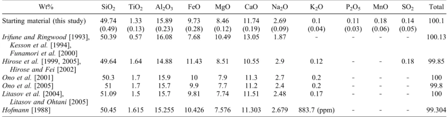
Wt% SiO2 TiO2 Al2O3 FeO MgO CaO Na2O K2O P2O5 MnO SO2 Total
Starting material (this study) 49.74 (0.49) 1.33 (0.13) 15.89 (0.23) 9.73 (0.28) 8.46 (0.12) 11.74 (0.19) 2.69 (0.09) 0.1 (0.04) 0.11 (0.03) 0.18 (0.06) 0.14 (0.05) 100.1 Irifune and Ringwood [1993],
Kesson et al. [1994], Funamori et al. [2000]
50.39 0.57 16.08 7.68 10.49 13.05 1.87 ‐ ‐ ‐ ‐ 100.13
Hirose et al. [1999, 2005], Hirose and Fei [2002]
49.64 1.64 14.88 11.43 8.51 10.55 2.9 0.12 ‐ ‐ 0.18 99.85 Ono et al. [2001] 50.3 1.7 15.9 10 7.9 11.3 2.7 0.2 ‐ ‐ ‐ 100 Ono et al. [2005] 51 1.7 15.7 9.9 7.7 11.2 2.4 0.2 ‐ ‐ ‐ 99.8 Litasov et al. [2004],
Litasov and Ohtani [2005]
51.09 1.5 15.7 9.81 7.74 11.51 2.48 0.17 ‐ ‐ ‐ 100 Hofmann [1988] 50.45 1.615 15.255 10.426 7.576 11.303 2.679 883.7 (ppm) ‐ ‐ ‐ 99.304
a
transmitting medium in runs MORB#1, #4, #5, and #6. MORB#3 was loaded with argon; MORB#2 and MORB#8 were loaded without medium. Neon pressure‐transmitting media was loaded using a 2000 bar high‐pressure, gas‐ loading apparatus [Couzinet et al., 2003]. Argon was cryo-genically loaded into the sample chamber.
2.3. In situ X‐Ray Diffraction
[8] In situ X‐ray diffraction experiments were performed
at the high‐pressure beamline ID30 (now relocated at ID27) at the European Synchrotron Radiation Facility (ESRF, Grenoble). The incident monochromatic X‐ray beam at 0.3738 Å was focused by two mirrors in Kirkpatrick‐Baez geometry into an X‐ray spot 8 × 9 mm2in size (full width at half maximum in vertical and horizontal direction, respec-tively), as obtained by scanning the X‐ray beam with a sharp edge.
[9] Two yttrium/aluminum/garnet (YAG) lasers (40 W
each) were focused through the diamond anvils onto the sample in a double‐sided, laser‐heating geometry. The hot spot was about 30–40 mm in diameter. Thermal emission of the sample was recorded on one side by a spectrometer during the X‐ray diffraction acquisition (for details, see Schultz et al. [2005]). Typical X‐ray diffraction patterns were acquired for 200 s. At least five thermal emission spectra of the sample were recorded during the data acqui-sitions to check the temperature stability, which was kept to within ±50 K. Angle‐dispersive X‐ray patterns were col-lected on a MAR® 345 image plate. The X‐ray diffraction patterns were recorded as a function of temperature; they increased step by step from 1600 K to 2700 K at a given loading pressure. Ambient temperature patterns were col-lected after high‐temperature cycles. Two‐dimensional dif-fraction patterns were integrated with the Fit2d program [Hammersley et al., 1996].
[10] Because of the large number of diffraction peaks in
X‐ray patterns, we did not add an internal pressure marker. To derive pressure conditions, we used variations in the unit‐cell volume of stishovite. The validity of this approach was assessed in several ways. First, chemical analysis of stishovite in our samples showed Al2O3contents less than
1 wt% (see Table 3 and Ricolleau et al. [2008] for more details). Second, at room temperature, pressures measured from the equation of state (EoS) of stishovite were in good agreement with pressures obtained from the equations of state of neon and argon (Hemley et al. [1989] and Jephcoat [1998], respectively) with the calculated pressure differ-ences less than 1 GPa (2–3%) by using EoS parameters of stishovite from Liu et al. [1999]. Third, we tested this set for high‐temperature data as follows. Similar studies on MORB composition by Ono et al. [2005] and Hirose et al. [2005] used gold as a pressure calibrant. Pressures given in latter studies agree within 5% to the pressures calculated from the thermal equation of state of stishovite given by Liu et al. [1999] (Figure 1). This validates the use of stishovite as an internal pressure scale in the present study. Stishovite transform from rutile‐type structure to CaCl2‐type structure
after 55 GPa [e.g., Andrault et al., 1998]. Since Andrault et al. [2003] observed that the CaCl2 form is only slightly
more compressible than the rutile‐type structure (i.e., 1.5 GPa at 90 GPa), and since there are no thermal parameters for the CaCl2‐type structure, we consider that using Liu et al.
[1999] EoS after 55 GPa is still valid. The transition pres-sure of stishovite will be discussed in the following section. [11] Rietveld refinements of the in situ XRD patterns were
performed with the GSAS package [Larson and Von Dreele, 2004] to determine the volumes and proportions of phases. After convergence, values of the residual, Rwp(function of
the observed intensity minus the calculated intensity; for more details, see Rietveld [1969] and Larson and Von Dreele [2004]), were always lower than 0.03. The crystal structure of the phases, atomic positions and thermal para-meters from the literature were used as fixed parapara-meters to refine the unit‐cell volumes and phase proportions. The structure of phases used to refine our XRD patterns are rutile‐type structure, space group P42/mnm for stishovite
[Ross et al., 1990], orthorhombic structure, space group Pbnm for Mg‐perovskite [Jephcoat et al., 1999], cubic structure, space group Pm3m for Ca‐perovskite, ortho-rhombic structure, space group Pbnm for the CF‐type phase [Yamada et al., 1983] and hexagonal structure, space group P63/m for the NAL phase [Gasparik et al., 2000]. A limited
subset of the in situ XRD results discussed in section 3 were previously published in Perrillat et al. [2006], namely MORB#1, MORB#2, MORB#3, MORB#4, and MORB#5 at room temperature and at about 2000 K to 2100 K. Here, we added higher pressure runs and refined the entire high temperature data set of all runs using the Rietveld method with the exception of MORB#1, which is too noisy for good refinement due to the intense neon peaks. MORB#1, MORB#4, MORB#5, and MORB#8 were also previously used for analytical TEM work [Ricolleau et al., 2008].
2.4. Analytical Transmission Electronic Microscopy
Investigation
[12] The recovered samples were placed on a conducting
carbon tape, and prepared for TEM observations. We used Figure 1. Pressure obtained from gold unit‐cell volumes in
the studies of Ono et al. [2005] and Hirose et al. [2005] compared with pressure derived from stishovite unit‐cell volumes in the same studies calculated with the equation of state of Liu et al. [1999].
Table 2. Volume and Proportion of Phases and Whole Assemblage Density as a Function of P ‐T Conditions a Temperature (K) Pressure (GPa) Mg ‐Perov Volumes (A 3) Proportions (wt%) Ca ‐Perov Volumes (A 3) Proportions (wt%) Stishovite Volumes (A 3) Proportions (wt%) CF Volumes (A 3) Proportions (wt%) NAL Volumes (A 3) Proportions (wt%) MORB#2 1628 28.7 (1.2) 159.117 (131) 22.70 41.956 (9) 30.07 43.783 (10) 21.85 221.921 (478) 10.71 164.729 (224) 14.68 1791 30.2 (1.2) 158.770 (159) 21.35 41.920 (10) 28.59 43.749 (9) 22.32 221.343 (435) 11.77 165.587 (153) 15.97 1931 30.4 (1.3) 159.521 (107) 17.24 41.947 (9) 32.66 43.856 (11) 22.33 221.270 (741) 11.91 165.961 (207) 15.86 2077 32.2 (1.3) 158.918 (163) 21.65 41.918 (10) 31.77 43.778 (10) 23.37 221.561 (285) 9.73 165.461 (114) 13.48 2229 32.7 (1.3) 159.654 (153) 22.42 42.008 (10) 30.08 43.863 (11) 22.82 221.868 (762) 10.06 165.428 (223) 14.62 2398 34.1 (1.4) 159.709 (154) 22.96 42.065 (11) 26.88 43.87 (13) 23.30 221.938 (457) 10.42 165.440 (194) 16.43 300 22.7 (0.1) 158.534 (165) 20.82 41.79 (9) 30.03 43.612 (10) 21.64 220.326 (610) 12.11 164.353 (256) 15.40 300 21.4 (0.1) 159.011 (171) 20.18 41.921 (10) 30.25 43.749 (9) 22.73 221.600 (454) 10.15 165.018 (197) 16.69 MORB#3 1779 34.4 (1.2) 157.779 (98) 31.53 41.571 (9) 26.30 43.276 (11) 15.70 217.612 (261) 10.09 165.226 (133) 16.38 1954 35.2 (1.3) 158.276 (111) 33.36 41.621 (10) 26.16 43.34 (11) 15.32 218.289 (243) 9.21 165.432 (119) 15.94 2149 36.2 (1.3) 158.493 (95) 37.31 41.716 (10) 24.44 43.395 (12) 14.82 218.244 (242) 8.56 166.025 (131) 14.86 2350 36.8 (1.4) 158.753 (116) 29.01 41.824 (10) 26.44 43.506 (13) 16.98 219.059 (254) 10.62 165.587 (124) 16.96 2526 37.8 (1.4) 158.371 (112) 27.36 41.86 (10) 33.62 43.564 (10) 17.58 219.359 (433) 4.65 165.863 (100) 16.78 300 29.2 (0.1) 155.546 (111) 30.59 41.131 (8) 28.67 42.952 (11) 14.10 215.074 (424) 8.07 163.332 (135) 18.58 300 28.9 (0.1) 155.467 (126) 30.57 41.127 (9) 27.63 42.976 (11) 14.44 216.704 (421) 9.41 163.77 (134) 17.95 300 29.2 (0.1) 156.184 (158) 34.68 41.137 (9) 23.26 42.947 (11) 13.53 213.512 (959) 10.31 163.476 (141) 18.21 300 0.0 168.342 (76) 46.681 (5) 243.949 (149) 183.017 (146) MORB#4 b 1993 43.2 (1.4) 152.274 (96) 30.32 40.513 (15) 32.13 42.543 (20) 18.44 212.011 (938) 12.86 163.175 (419) 6.26 2104 41.8 (1.4) 153.222 (143) 28.29 40.991 (26) 31.24 42.77 (24) 19.40 218.218 (1.168) 13.82 163.709 (210) 7.26 2225 43.6 (1.4) 153.918 (115) 35.44 41.029 (18) 29.68 42.685 (15) 19.62 214.191 (727) 9.81 164.081 (249) 5.44 2291 43.6 (1.4) 154.674 (154) 35.97 41.118 (20) 33.23 42.739 (18) 19.64 212.748 (727) 8.64 163.818 (368) 2.51 2391 44.8 (1.5) 154.483 (189) 38.82 41.138 (26) 25.58 42.701 (22) 20.06 210.394 (453) 9.44 163.775 (265) 6.10 300 35.5 (0.1) 151.297 (81) 40.78 40.26 (10) 25.26 42.357 (13) 16.72 211.914 (594) 9.57 161.125 (228) 7.67 300 36.0 (0.2) 151.511 (98) 39.14 40.349 (13) 24.32 42.314 (18) 19.53 209.736 (855) 9.22 161.054 (597) 7.79 300 35.1 (0.2) 151.343 (102) 33.59 40.157 (18) 25.31 42.396 (16) 18.52 214.979 (583) 15.36 161.148 (126) 7.21 MORB#5 2055 52.4 (1.3) 148.661 (81) 49.46 39.247 (9) 29.57 41.742 (13) 13.34 206.252 (174) 7.63 2064 49.8 (1.4) 149.937 (105) 46.86 39.146 (11) 30.20 41.977 (17) 14.85 207.289 (395) 8.09 2217 52.6 (1.4) 150.459 (110) 45.07 39.191 (13) 26.90 41.828 (15) 17.03 207.136 (264) 11.00 2270 53.8 (1.4) 148.981 (86) 45.20 39.234 (9) 33.26 41.759 (13) 14.33 206.440 (160) 7.21 2314 54.7 (1.4) 148.214 (57) 46.77 39.160 (9) 27.83 41.713 (13) 15.71 207.269 (340) 9.69 2500 54.2 (1.4) 150.123 (107) 43.31 39.427 (16) 31.35 41.897 (18) 16.28 207.656 (229) 9.06 2550 55.2 (1.4) 149.825 (126) 41.29 39.322 (15) 31.30 41.841 (17) 15.73 208.121 (339) 11.68 2693 55.4 (1.4) 149.62 (90) 44.59 39.152 (10) 31.16 41.933 (14) 14.64 207.298 (311) 9.60 300 42.3 (0.2) 148.35 (59) 46.68 39.105 (9) 29.55 41.776 (13) 14.69 206.858 (323) 9.08 300 43.4 (0.1) 147.583 (50) 42.76 39.079 (8) 31.12 41.68 (11) 15.64 206.616 (252) 10.48 300 43.2 (0.1) 147.521 (45) 47.32 39.139 (8) 28.69 41.698 (11) 14.92 206.909 (282) 9.07 300 43.0 (0.1) 147.562 (44) 44.85 39.159 (7) 30.64 41.714 (12) 14.70 207.107 (306) 9.81 300 43.5 (0.1) 147.675 (47) 40.03 39.156 (7) 31.04 41.672 (10) 16.94 206.978 (254) 11.98 300 42.7 (0.1) 148.219 (52) 46.51 39.074 (9) 30.91 41.743 (12) 14.35 206.815 (280) 8.23 300 0.0 169.840 (230) 46.848 (7) 244.637 (277) MORB#6 c 1783 58.1 (1.6) 145.403 (102) 38.278 (21) 41.097 (44) 200.105 (466) 2023 61.8 (2.1) 145.033 (128) 38.256 (16) 40.938 (76) 201.538 (756) 2137 63.1 (1.8) 145.150 (88) 38.246 (12) 40.899 (51) 202.236 (903) 2183 62.4 (1.9) 145.527 (139) 38.361 (15) 40.984 (56) 203.297 (794) 2337 64.2 (2.1) 144.931 (132) 38.186 (27) 40.933 (69) 204.347 (1.262)
Table 2. (continued) Temperature (K) Pressure (GPa) Mg ‐Perov Volumes (A 3) Proportions (wt%) Ca ‐Perov Volumes (A 3) Proportions (wt%) Stishovite Volumes (A 3) Proportions (wt%) CF Volumes (A 3) Proportions (wt%) NAL Volumes (A 3) Proportions (wt%) 2430 61.5 (1.7) 146.336 (122) 38.497 (15) 41.212 (38) 202.446 (847) 2433 64.2 (1.8) 145.386 (98) 38.325 12) 40.996 (45) 203.752 (769) 2543 63.7 (2.0) 146.458 (141) 38.485 (16) 41.106 (63) 204.311 (922) 300 55.7 (1.4) 144.189 (134) 37.955 (23) 40.739 (100) 201.256 (571) 300 54.8 (0.8) 144.289 (132) 37.974 (18) 40.802 (61) 201.284 (699) MORB#8 d 1796 80.3 (1.3) 139.208 (77) 41.15 37.083 (9) 32.86 39.504 (23) 14.87 192.370 (150) 11.12 1876 80.4 (1.3) 139.397 (76) 42.60 37.128 (9) 30.31 39.531 (21) 14.28 192.542 (145) 12.81 1963 79.7 (1.4) 139.961 (80) 44.21 37.2 (9) 29.70 39.613 (22) 14.35 192.975 (136) 11.74 1973 80.5 (1.3) 139.433 (74) 43.39 37.165 (8) 30.77 39.568 (19) 14.34 192.738 (125) 11.50 2028 80.8 (1.4) 139.862 (67) 45.29 37.098 (11) 29.79 39.573 (22) 12.41 192.650 (268) 12.51 2121 80.2 (1.4) 140.142 (79) 44.34 37.241 (9) 29.64 39.655 (22) 14.55 193.229 (132) 11.47 2263 80.5 (1.5) 140.112 (76) 43.37 37.276 (10) 30.91 39.703 (22) 14.56 193.451 (136) 11.16 2294 83.8 (1.4) 138.538 (77) 41.06 37.182 (8) 31.60 39.502 (16) 14.35 192.584 (231) 12.99 2433 81.1 (1.5) 140.239 (74) 43.54 37.324 (9) 30.46 39.753 (22) 14.72 193.766 (130) 11.28 2580 81.2 (1.5) 140.727 (74) 44.21 37.387 (10) 29.57 39.822 (23) 15.02 194.282 (130) 11.21 300 77.6 (0.4) 138.269 (83) 41.34 36.847 (10) 32.95 39.314 (22) 13.95 191.067 (166) 11.75 300 79.1 (0.4) 137.994 (82) 40.39 36.776 (10) 32.89 39.226 (26) 15.40 190.653 (167) 11.32 300 80.0 (0.3) 137.261 (73) 42.80 36.706 (9) 32.48 39.173 (19) 14.35 190.085 (183) 10.37 300 76.3 (0.4) 138.235 (73) 43.18 36.973 (10) 31.24 39.395 (21) 14.23 191.359 (195) 11.36 1813 87.0 (1.3) 136.146 (56) 43.16 36.715 (7) 30.65 39.092 (18) 14.98 193.063 (281) 11.21 1967 87.3 (1.3) 136.296 (52) 41.86 36.769 (7) 29.82 39.130 (18) 15.30 193.343 (285) 13.03 2115 87.7 (1.4) 137.040 (68) 43.25 36.796 (7) 29.75 39.170 (19) 15.29 190.266 (176) 11.70 2132 88.2 (1.4) 136.523 (59) 43.02 36.778 (7) 29.84 39.149 (21) 15.31 193.710 (385) 11.84 2134 87.7 (1.4) 136.577 (55) 42.57 36.823 (7) 29.03 39.181 (20) 15.43 193.732 (329) 12.97 2219 88.2 (1.4) 136.671 (59) 43.78 36.823 (7) 28.53 39.182 (20) 15.57 193.943 (336) 12.11 2248 88.1 (1.4) 136.688 (54) 40.56 36.832 (7) 30.56 39.204 (18) 15.51 194.015 (357) 13.37 2399 88.9 (1.4) 136.786 (57) 44.73 36.844 (7) 27.87 39.223 (20) 15.76 194.108 (336) 11.64 300 84.0 (0.3) 135.322 (52) 36.78 36.523 (10) 35.47 38.947 (18) 14.33 191.494 (290) 13.42 300 84.5 (0.3) 135.798 (77) 37.92 36.497 (9) 35.23 38.920 (19) 15.07 188.648 (231) 11.78 300 85.1 (0.4) 135.812 (83) 39.43 36.469 (9) 34.09 38.885 (21) 15.52 188.542 (212) 10.96 300 85.2 (0.4) 135.763 (84) 40.94 36.460 (9) 32.90 38.880 (21) 15.18 188.386 (202) 10.98 300 85.4 (0.4) 135.770 (83) 40.96 36.448 (9) 33.28 38.870 (20) 14.86 188.338 (194) 10.91 aNumbers in parentheses are 1s error in last digits. b In run MORB#4, the error bars are larger than the other runs because of an important proportion of our transmitting pressure medium, i.e., neon. cIn run MORB#6, the proportion of phase were not refined because of a much too strong proportion of neon in the XRD patterns. d In run MORB#8, two sets of pressures are presented at high ‐pressure and high ‐temperature. The first set was initially collected at 80 GPa before raising the pressure up to 89 GPa.
the focused ion beam (FIB)“lift‐out” technique [Giannuzzi and Stevie, 1999] to extract thin film from the laser‐heated sample area. The preparation was performed with a FEI Model 200 TEM FIB system at the University Aix‐Marseille III. The FIB system uses a gallium liquid metal ion source, which allows milling. At the end of the milling, the thin
film of ∼15 mm length and ∼5 mm width with a thickness
of ∼100 nm was removed from the recovered sample and
deposited onto a TEM grid.
[13] Selected area electron diffraction (SAED) patterns
were obtained on several grains for phase identification
using a 200 kV JEOL‐2100F TEM at the Institut de
Minéralogie et Physique des Milieux Condensés (Paris, France). The chemical compositions of the phases were measured with a 300 kV Philips CM30 transmission elec-tron microscope equipped with a Noran Instruments energy‐ dispersive analytical system (EDS) at Laboratoire de Structure et Propriétés de l’Etat Solide in Lille (for details, see Ricolleau et al. [2008]).
3.
Results
3.1. Unit‐Cell Volume of MORB High‐Pressure Phases
[14] Six runs, conducted at pressures between 28 GPa and
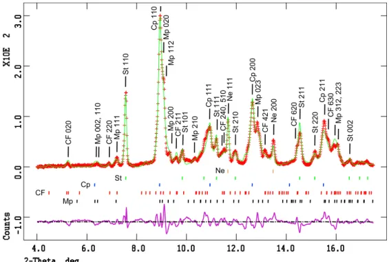
89 GPa, and at high temperature, show resolvable XRD patterns (MORB#1 was only used for TEM work, MORB#7 is absent because of poor‐quality XRD patterns). Pressure‐ temperature conditions and the results of XRD patterns refinement are presented in Table 2. Figure 2 shows an example of an X‐ray pattern obtained at 53 GPa and 2200 K and the corresponding refined pattern. Diffraction lines were assigned to stishovite, Ca‐perovskite, aluminum‐bearing Mg‐
Figure 2. In situ X‐ray diffraction pattern acquired at 53 GPa and 2200 K (red line) and its refined pattern (green line). Tick marks stand for diffraction peaks of Mg‐perovskite, CF‐type phase, Ca‐perovskite, stisho-vite and neon, from bottom to top. The main diffraction peaks of each phase are indexed on top of the pattern.
Figure 3. Evolution of X‐ray diffraction patterns acquired at 300 K with pressure. The arrows point the peak of stisho-vite, (211) in rutile‐type SiO2(P42/mnm). After 55 GPa, the
peak split into two peak, (121) and (211), due to the transi-tion to the CaCl2‐type SiO2(Pnnm). Tick marks indicated by
circles and triangles are peaks (620) and (131) of CF‐type phase and Mg‐perovskite, respectively.
perovskite, and CF‐type phase. These phases were observed at all pressures between 28 and 89 GPa. Experiments carried out at pressures below 45 GPa are characterized by the occurrence of the NAL phase, which disappears at higher pressure [Perrillat et al., 2006]. The observed mineral assemblages are in good agreement with previous DAC studies on MORB [Kesson et al., 1994; Ono et al., 2005; Hirose et al., 2005]. In runs MORB#6 and MORB#8 (i.e., at 60 and 89 GPa), we observed splitting of reflections 101 and 211 of stishovite into 011–101 and 121–211 doublets, corresponding to the phase transition from the rutile‐type structure into the CaCl2‐type structure of SiO2 [e.g.,
Andrault et al., 1998]. Figure 3 shows the evolution of the room temperature XRD patterns around the 211 peak of stishovite with increasing pressure, with splitting of the peak after 55 GPa clearly visible. Recent studies by Bolfan‐ Casanova et al. [2009] and Lakshtanov et al. [2007] show that the transition starts around 25 GPa in stishovite
con-taining about 4 wt% Al2O3. Lakshtanov et al. [2005]
observed no transition up to at least 44 GPa and a possi-ble beginning of the transition at 49 GPa by studying stishovite containing 1.8 wt% Al2O3. Our higher‐pressure
transition is in good agreement with our chemical analysis
on stishovite giving less than 1 wt% Al2O3(see Table 3). In
the Rietveld refinement, we subsequently used the CaCl2‐
type structure from Haines et al. [1996] at higher pressures. The transition in stishovite structure occurs between 55 and 62 GPa at high temperature in our sample, which is in good agreement with the study of Hirose et al. [2005] where it is observed between 58 and 68 GPa.
[15] For Ca‐perovskite, recent studies have shown a phase
transition that occurs at about 600 K in pure CaSiO3
between tetragonal and cubic structures [e.g., Shim et al., 2002, Komabayashi et al., 2007]. This phase transition is a second‐order phase transition without any volume change [Komabayashi et al., 2007]. We observed a splitting of the 200 peak only in few of our room temperature XRD patterns. More frequently, a shoulder is just barely observable. Therefore, we used the cubic structure to refine the volume of Ca‐perovskite. Kurashina et al. [2004] observed a transition between orthorhombic and cubic structures with increasing temperature in an aluminum‐bearing Ca‐perovskite. In our XRD patterns, the presence of multiple phases including orthorhombic Mg‐perovskite makes such observation very difficult. Nevertheless, the intensity of the cubic Ca‐perovskite peaks does not change from high temperature to room
tem-Table 3. Chemical Composition Obtained by Analytical Transmission Electronic Microscopy on MORB Samples Recovered From
High‐Pressure High Temperature Experimentsa
Mgpv St Capv CF NAL 33 GPa/MORB#1 SiO2(wt%) 45.4 (1.9) 98.8 (0.3) 51.6 (0.1) 26.0 (1.3) 26.5 (1.5) TiO2(wt%) 3.6 (0.0) 0.1 (0.1) 1.3 (0.4) 0.4 (0.2) 0.3 (0.2) Al2O3(wt%) 13.4 (0.7) 0.5 (0.2) 3.3 (0.4) 37.8 (0.9) 38.9 (2.2) FeO (wt%) 14.0 (0.9) 0.1 (0.2) 3.5 (1.3) 14.0 (0.5) 8.7 (1.0) MgO (wt%) 20.8 (2.0) 0.0 (0.1) 1.4 (1.1) 12.7 (1.7) 17.7 (1.2) CaO (wt%) 2.7 (1.5) 0.4 (0.3) 38.8 (2.5) 1.3 (0.3) 2.2 (0.4) Na2O (wt%) 0.0 (0.0) 0.0 (0.0) 0.0 (0.0) 7.9 (1.5) 5.9 (0.4) Proportions 23 (5) 17 (2) 28 (2) 22 (5) 10 (5) Weight (g/mol) 109.26 60.17 115.56 152.03 148.91
Weight after correction 110.96 60.17 115.56 153.10 150.37 44 GPa/MORB#4 SiO2(wt%) 42.3 (1.4) 98.7 (0.4) 51.9 (0.4) 28.5 (2.1) 23.3 (0.4) TiO2(wt%) 2.5 (0.3) 0.1 (0.1) 1.3 (0.2) 0.5 (0.3) 0.3 (0.1) Al2O3(wt%) 21.2 (1.4) 0.8 (0.2) 3.5 (0.8) 39.8 (1.9) 45.0 (0.7) FeO (wt%) 11.3 (1.4) 0.1 (0.1) 4.4 (0.9) 9.7 (2.4) 4.7 (0.4) MgO (wt%) 18.7 (1.2) 0.0 (0.1) 3.2 (1.5) 11.0 (3.3) 18.9 (0.6) CaO (wt%) 3.5 (0.7) 0.1 (0.1) 35.7 (1.8) 1.3 (0.4) 1.9 (0.4) Na2O (wt%) 0.5 (0.3) 0.0 (0.0) 0.1 (0.1) 9.2 (1.1) 5.9 (0.2) Proportions 38 (5) 15 (2) 30 (2) 12 (3) 6 (2) Weight (g/mol) 107.88 60.12 114.88 149.38 146.16
Weight after Correction 110.44 60.12 114.88 151.53 147.94 55 GPa/MORB#5 SiO2(wt%) 40.9 (0.6) 98.5 (0.4) 52.1 (0.2) 26.7 (0.4) TiO2(wt%) 2.1 (0.2) 0.1 (0.1) 1.2 (0.1) 0.2 (0.1) Al2O3(wt%) 23.6 (0.9) 0.9 (0.1) 2.5 (0.7) 43.2 (1.3) FeO (wt%) 10.1 (0.5) 0.1 (0.1) 3.5 (0.6) 6.2 (1.1) MgO (wt%) 19.1 (0.6) 0.1 (0.1) 3.9 (1.1) 12.9 (1.7) CaO (wt%) 3.3 (0.3) 0.4 (0.3) 36.8 (2.5) 1.7 (0.6) Na2O (wt%) 0.8 (0.2) 0.0 (0.0) 0.1 (0.1) 9.1 (0.2) Proportions 40 (4) 16 (1) 29 (2) 15 (2) Weight (g/mol) 107.05 60.16 114.63 147.02
Weight after Correction 110.35 60.16 114.63 149.39
a
Mgpv, magnesium perovskite; St, stishovite; Capv, calcium perovskite; CF, calcium ferrite‐type phase; NAL, new aluminum‐rich phase. Proportions in wt% obtained from least squares mass balance calculation. Numbers in parentheses are the standard deviation (1s).
perature. The proportions of Ca‐perovskite obtained by the Rietveld refinement remain constant at all temperatures (see Table 2).
3.2. Chemical Composition of Phases
[16] Samples from runs MORB#1 MORB#4, and
MORB#5 were recovered and prepared for analytical TEM analysis. Run MORB#1 (P = 33 GPa), showed weak dif-fraction patterns making the Rietveld method of analysis difficult to perform: some analyzed patterns were previously reported in Perrillat et al. [2006], and the recovered sample was studied by TEM. Every phase observed in the in situ X‐ray diffraction patterns was confirmed by selected area electron diffraction patterns. Stishovite, Mg‐perovskite, Ca‐perovskite, CF‐type phase, and the NAL phase were observed at 33 GPa (MORB#1) and 44 GPa (MORB#4). At 55 GPa (MORB#5), the NAL phase has disappeared. In all samples, both perovskites are amorphous upon recovery; nevertheless, they can be distinguished by their different contrast in backscattered and transmitted electron images and by their different chemical composition [Ricolleau et al., 2008]. The protocol used for quantifying chemical compo-sitions is described in Ricolleau et al. [2008]. The composi-tions of each phase for the preceding three pressures are shown in Table 3. The Al2O3 content of Mg‐perovskite is
13 wt% in MORB#1 and increases with pressure up to 24 wt% in MORB#5 synthesized at 55 GPa. Similarly, the Al2O3
content of CF‐type phase increases with pressure, from 38 wt% at 33 GPa to 43 wt% once the NAL phase dis-appears at pressure exceeding 55 GPa. Thus, the Al increase
in Mg‐perovkite and CF‐type phase might be linked to the NAL phase disappearance. On the other hand, the Al2O3
content in stishovite never exceeds 1 wt% at any pressure. The modal mineralogy was estimated using mass balance and by assuming that the bulk chemical composition of the samples is equal to the starting composition (Table 3).
[17] Chemical mass balance showed that laser‐heated
areas were affected by 15%–40% iron loss and
commen-surate magnesium enrichment. We observed that the iron loss is about 16%, 27%, and 38% in samples synthesized at 33, 44, and 55 GPa, respectively. At the same time, mag-nesium enrichment is about 15%, 24%, and 27%, respec-tively. Iron diffusion has been observed in laser‐heated DAC samples [e.g., Sinmyo et al., 2008; Hirose et al., 2005] due to the large thermal gradient, which is known as the Soret effect.
[18] Mass balance calculation shows a loss of sodium of
about 14%, 38%, and 36% in our samples synthesized at 33, 44, and 55 GPa, respectively. FIB milling use gallium ions bombardment, which leads to significant Ga implantation in the slice. Ga La line is very close in energy to the Na Ka line, the two peaks are then correlated. This lack of sodium is mainly due to a correlation of peaks that cannot be solved and is not constant through samples.
3.3. Equation of State of MORB High‐Pressure Phases
[19] The thermoelastic parameters of the observed phases
were deduced from our dataset using a numerical code based on the generalized nonlinear inversion technique [Tarantola and Valette, 1982] and a third‐order Birch‐Murnaghan
Table 4. Summary of P‐V‐T Equation of State Parameters for MORB High‐Pressure Phases Compared With Previous Studiesa
V0(A3) K0,T(GPa) K′0,T (dK/dT)P(GPaK−1) a0(10−5K−1) a1(10−8K−2)
Mg‐perovskite 170.0 (1) 238 (2) 4 (fixed) −0.044 (2) 2.82 (35) 1.65 (33) This study 170.0 (1) 239 (3) 3.98 (7) −0.044 (2) 2.83 (35) 1.62 (34) This study
169.7 (2) 225 (5) 4.72 (11) −0.048 (6) 0.80 (55) 3.61 (71) This study, after NAL disappearance 169.5 (fixed) 217 (2) 4 (fixed) Hirose et al. [2005] 163.51 (6) 232 4 (fixed) Yagi et al. [2004], En90 164.85 253.4 (6.2) 4 (fixed) Walter et al. [2004], En75 CF‐type phase 243.3 (2) 197 (1) 4 (fixed) −0.007 (2) 1.96 (22) This study
244.2 (2) 174 (3) 4.86 (12) −0.013 (3) 2.56 (27) This study
244.6 (3) 168 (3) 5.09 (15) −0.004 (5) 1.63 (51) This study, after NAL disappearance 239.7 (1.5) 214 (8) 4 (fixed) Hirose et al. [2005]
242.7 (3) 193 (2) 4 (fixed) Guignot and Andrault. [2004], exp. 6
245.4 (6) 200 (5) 4 (fixed) Guignot and Andrault [2004], exp. 7
244.07 (55) 253 (14) 3.6 (6) Ono et al. [2002] Ca‐perovskite 45.58 (fixed) 223 (1) 4 (fixed) −0.011 (2) 2.21 (18) This study
45.58 (fixed) 209 (1) 4.8 (fixed) −0.021 (2) 2.86 (20) This study 45.58 (fixed) 194 (1) 5.78 (05) −0.029 (2) 3.51 (20) This study 45.6 (2) 245 (6) 4 (fixed) Hirose et al. [2005] 45.58 (4) 232 (8) 4.8 (3) −0.033 (8) 3.0 Wang et al. [1996] 45.58 (4) 236 (4) 3.9 (2) −0.028 (11) 2.2 (3) Shim et al. [2000] r (g/cm3) K
0,T(GPa) K′0,T (dK/dT)P(GPaK−1) a0(10−5K−1)
MORB density 4.25 (1) 246 (5) 4 (fixed) −0.025 (5) 2.83 (27) This study
4.25 (1) 245 (5) 4 (fixed) −0.022 (5) 2.59 (40) This study, after NAL disappearance
a
equation of state. The best‐fit elastic parameters are reported in Table 4, for either a fixed K′ = 4 or a refined K′. As unit‐ cell volumes of the NAL phase could not be obtained over a wide enough pressure range, its elastic parameters could not be constrained.
[20] To check for significant changes of the behavior of
the phases due to NAL phase disappearance, we refitted the
thermoelastic parameters of Mg‐perovskite and CF‐type
phase using only the volumes measured at pressures above 50 GPa (Table 4). The elastic parameters of Ca‐perovskite after NAL disappearance are not given because the fit convergence was poor (i.e., c2 > 2). The thermoelastic parameters obtained for Mg‐perovskite and CF‐type phase indicate a change in the thermoelastic behavior of these two phases before and after the NAL phase disappearance. However, it should be noted that the second sets of para-meters were obtained over a limited pressure range. The change in thermoelastic behavior is likely due to the change in chemical composition of these phases as the NAL phase disappears [Ricolleau et al., 2008]. The Al2O3content in the
Mg‐perovskite and CF‐type phase increase with pressure as mentioned in a previous section.
[21] Table 4 also shows the elastic parameters available in
the literature for comparison. The bulk modulus obtained on the aluminum‐bearing Mg‐perovskite is significantly lower
than that of the MgSiO3 end‐member. This is in good
agreement with several works that studied the behavior of Mg‐perovskite with incorporating aluminum; these works showed that increasing aluminum content in Mg‐perovskite decreased its bulk modulus [e.g., Nishiyama et al., 2007]. The bulk modulus of CF‐type phase and Ca‐perovskite are also slightly lower than those given in the literature for end‐
member compositions. The bulk modulus of the CF‐type
phase obtained on a similar composition by Guignot and Andrault [2004] is in agreement (Table 4). Concerning Ca‐perovskite, we assume that its aluminum content could cause the difference in compressibility with CaSiO3 end‐
member.
[22] Figure 4 displays the changes of the unit‐cell volume
of Mg‐perovskite, CF‐type phase, and Ca‐perovskite as a function of pressure at different temperatures, compared with the isotherms calculated using the fitted thermal EoS parameters. The volumes of each phase at room temperature obtained by Hirose et al. [2005] on a MORB composition are plotted for comparison. We note that the volume of Ca‐ perovskite and the CF‐type phase are in good agreement with our measurements. The volumes of Mg‐perovskite given in the study of Hirose et al. [2005] deviate from our
volume at pressures above 60 GPa by about 3%. Our Mg‐
perovskite contains more aluminum than the one in the study of Hirose et al. [2005], which might explain this difference. As shown in Figure 4a, the volume of Mg‐ perovskite below 35 GPa cannot be fitted well by the EoS parameters obtained on the entire range. As we study an assemblage where phase chemistry is not constant though pressure, this observation can be attributed to a large change in Mg‐perovskite composition. Indeed, at 35 GPa the NAL phase is disappearing, and the Al2O3content of Mg‐perovskite
nearly doubles from 13 wt% to 24 wt% (Table 3). Compression curves for the other phases do not show the effect seen for Mg‐ perovskite, most likely because their chemistry changes less drastically at NAL phase disappearance.
Figure 4. Variation of volume as a function of pressure at room temperature and at high temperature for Mg‐preovskite, CF‐type phase and Ca‐perovskite. Isotherms are calculated at temperatures between 300 K and 2400 K using refined thermoelastic parameters.
3.4. Proportion of Phases
[23] The relative amounts of each phase (Table 2) were
obtained by Rietveld refinement of in situ XRD patterns [see Perrillat et al., 2006 for further details]. The chemical compositions obtained by analytical TEM were used to specify the unit‐cell composition of the phases. Only sam-ples MORB#1, MORB#4, and MORB#5 (synthesized at 33, 44, and 55 GPa, respectively) were successfully analyzed by analytical TEM, in terms of chemical compositions of the coexisting phases. Consequently, we used the compositions obtained on MORB#1 for MORB#2 and MORB#3 (per-formed at 33 and 36 GPa, respectively) because these runs were performed in the same range of pressure and tempera-ture. Because no phase change was observed between 55 and 89 GPa in our X‐ray diffraction experiments, we assume that chemical composition changes were minor and would not significantly modify our density calculations. Therefore, the compositions determined from sample MORB#5 (55 GPa) were used for MORB#6 and MORB#8 (performed at 64 and 89 GPa, respectively).
[24] Mineral proportions determined from Rietveld
refine-ment of the XRD patterns were also compared with mineral proportions determined from mass balance calculations of the chemical compositions of phases. The two methods are in agreement within the error bars (see Tables 2 and 3 for comparison).
[25] In each run, we compared phase proportions obtained
from our XRD refinements at different temperatures and did not observe any significant change in mineral proportions, within the uncertainty. This might indicate that mineral abundances in MORB at subsolidus conditions do not change significantly with temperature. In the following section, we assumed no change of chemical composition with temperature at a given pressure.
[26] Average proportions obtained for each run are
reported as a function of pressure in Figure 5. At the lowest
pressure, around 30 GPa, the major phase is Ca‐perovskite, followed by Mg‐perovskite and stishovite, the NAL phase, and finally the CF‐type phase. At 40 GPa, Mg‐perovskite is the most abundant phase, followed by Ca‐perovskite, stishovite, CF‐type phase, and finally the NAL phase. At higher pressure, this order does not change, but the NAL phase disappears. At pressures between 30 and 50 GPa, the variation in the proportions of the different phases, namely the decrease of the NAL phase and the increase of Mg‐ perovskite content can be explained as a response to the changes in phase compositions (i.e., the aluminum solubility increase in Mg‐perovskite). At pressures of 50 and 80– 88 GPa, the proportion of each phase remains constant within experimental error. In run MORB#6 at 60 GPa, the high intensity of neon peaks in the XRD patterns precluded refinement of phase proportions. Because no significant mineralogical changes were observed from 50 to 89 GPa, proportions obtained at 50 GPa (MORB#5) were used to obtain the densities for run MORB#6 at 60 GPa.
3.5. MORB Density
[27] We obtained experimentally the unit‐cell volumes,
proportions, and compositions of each phase to be able to calculate the density of the whole assemblage at each pressure‐temperature condition investigated. As already described, our chemical compositions show a loss of iron, which is an element of major importance for density cal-culation. Since we observe this iron loss commensurate with magnesium enrichment, we decided to apply a correction involving adding iron and subtracting magnesium from our phases. Mg‐perovskite, CF‐type phase, and NAL phase are the major hosts of Fe and Mg. To be able to reduce iron loss and magnesium enrichment to less than 5%, we added 3, 4.6, and 6 wt% FeO accompanied by the same subtraction of MgO in Mg‐perovskite for MORB#1, MORB#4. and MORB#5, respectively. By keeping the partition coefficient Figure 5. Variation of mineral proportion obtained by Rietveld refinement on XRD patterns as a
func-tion of depth. Cpx, clinopyroxene; Gt, garnet; St, stishovite in rutile‐type structure and in CaCl2‐type
structure; NAL, new Al‐rich phase; CF, calcium ferrite‐type phase; Capv, calcium perovskite; Mgpv, aluminum‐bearing magnesium perovskite. Phase proportions at pressures less than 30 GPa are taken from multianvil experiments [Irifune et al., 1986, Irifune and Ringwood, 1993; Litasov and Ohtani, 2005].
of Fe and Mg between these phases unchanged (within 15% of the initial value) and maintaining the mass balance requirement, we added 1.4, 3, 3.3 wt% FeO in the CF‐type phase, respectively, and 2 and 2.5 wt% FeO in NAL phase for MORB#1 and MORB#4, respectively, accompanied by the same subtraction of magnesium. Table 3 shows the weight obtained for each phase before and after this correction.
[28] The unit‐cell volumes, proportions, and corrected
compositions of each phase were used to calculate the density of the whole assemblage at each pressure‐temperature con-dition investigated. The density values are displayed as a function of pressure and temperature in Figure 6, along the PREM density profile [Dziewonski and Anderson, 1981]. The density values from Ono et al. [2005] and Hirose et al. [2005] using similar starting compositions are also plotted for comparison. Below 60 GPa, our result is similar to the result of Hirose et al. [2005]. The densities determined by Ono et al. [2005] are lower than ours, and those determined by Hirose et al. [2005] are higher after 60 GPa. The dis-crepancy observed at pressures above 60 GPa might be due to the difference observed in the compression curve of Mg‐ perovskite from the two studies (Figure 4a) and the differ-ence in pressure scale. The discrepancy between our result and those of Ono et al. [2005] is difficult to determine since they have few data points obtained exclusively at high temperatures. The difference might be due to a difference in pressure scale (i.e., they use gold as a pressure calibrant with the pressure scale of Jamieson et al. [1982]) and a difference in determined volumes of phases. Mass balance calculation
also shows a loss of iron of about 15% in Ono et al. [2005] and Hirose et al. [2005] studies. Correcting this loss would not change significantly the observed discrepancy.
[29] We used our zero‐pressure densities and the one
given by Ono et al. [2001] combined with our high‐pressure data set at room temperature and at high temperature to determine the thermoelastic parameters using a generalized inversion as describe in previous section. Zero pressure
density was obtained using X‐ray diffraction data from
samples MORB#3 and MORB#5 quenched to ambient conditions (see Table 2). Since Ca‐perovskite is amorphous at ambient pressure, we used the value of V0 = 45.58 A3
from Wang et al. [1996] to obtain its room conditions density. Thermoelastic parameters were obtained by fitting our data set with the pressure derivative of the bulk modu-lus, K′, fixed to 4. The set of parameters obtained is reported in Table 4. The influence of the disappearance of the NAL phase on the equation‐of‐state parameters was checked by fitting the densities using only the data obtained above 50 GPa; the zero pressure densities are also used to constrain the fit. The fitting results, listed in Table 4, showed that the disappearance of the NAL phase does not significantly affect the EoS parameters of MORB. This is rather different from the effect of the NAL disappearance on the volume variation of each individual phase, especially for the Mg‐ perovskite EoS. This difference in behavior of the bulk density EoS and the EoS of each individual phase can be explained by the compositional variations of phases. Indeed, aluminum‐bearing Mg‐perovskite contains more aluminum
Figure 6. Density of MORB at high‐pressure high‐temperature compared to PREM. Symbols represent
densities calculated in the present study using data obtained at 300 K (solid circles), less than 1800 K (open triangles), between 1900 K and 2100 K (open circles), between 2200 K and 2300 K (cross squares), and to 2600 K (inverse solid triangles). Calculated isotherms at 1600 K, 2000 K, and 2400 K with our thermoelastic parameters from Table 4 are shown. Density data obtained by Ono et al. [2005], and by Hirose et al. [2005] at room temperature and at high temperature are indicated by ×, +, and stars, respectively.
after the NAL phase has disappeared. The changes in
composition and volume compression of Mg‐perovskite
seem to compensate any potential density jump.
[30] The density profiles of MORB along isotherms of
1600 K to 2400 K calculated using the EoS parameters are shown in Figure 6. With the EoS parameters, we calculated the density profiles of MORB along different mantle tem-perature profiles. First, we used two thermal profiles corresponding to a hot and a cold slab as calculated by Ricard et al. [2005] for an oceanic lithosphere with veloc-ities of 3 and 10 cm/yr, respectively, which includes the most current range of plate velocities [Gripp and Gordon, 2002]. Moreover, temperature profiles of the subducting slabs have been calculated using different thermal models [e.g., Meade and Jeanloz, 1991; Kirby et al., 1996]. These models gave very similar temperature profile for a hot slab. For a cold slab, the previous models predicted much lower temperature, as low as 900 K at 670 km depth. We calcu-lated the density profile of MORB with this very low tem-perature profile as well. We also calculated the density of MORB in a subducting slab thermally equilibrated with the surrounding mantle. The adiabatic geotherm from Brown and Shankland [1981] was used. Figure 7 shows the den-sity differentials between MORB and the surrounding mantle with the MORB density profiles calculated using slab temperature profiles for a cold and a hot slab and using the very cold temperature profile given in the literature and the geotherm of Brown and Shankland [1981]. Depending
on the temperature profile, the density differential is between 2% and almost 4% at depths beyond the transition zone and near 2% at the bottom of the lower mantle.
[31] For a better comparison, the difference between the
two average density profiles of the Earth’s mantle (i.e., PREM and ak135) [Kennett et al., 1995] is shown in Figure 7. Nevertheless, the error bar given for PREM is ±0.05% [Silver et al., 1988], which is larger than the dif-ference between the PREM and ak135 density profiles. The conclusion does not change by taking into account the error bar.
[32] Since we obtained the EoS of each phase present after
50 GPa, we were able to obtain the density profile of each individual phase and to calculate the MORB density profile by using the phase proportions. The MORB density profile calculated using the thermoelastic parameters obtained on each phase is very close to the density profile obtained by using the elastic parameters. These two profiles are plotted in Figure 8, using shaded and solid lines, respectively. This gives an error on our profiles of about 0.2%. We attempted a possible sodium correction on our compositions and ended up with a difference of about 0.1% on the density profile. This makes a final error of about 0.3% on the density dif-ferential. Thus, in all cases, MORB is always denser than Figure 7. Density differentials of MORB samples
com-pared to PREM calculated along the temperature profiles of a cold and a hot slab (solid and long‐dashed lines), and calculated along the temperature profile of a very cold slab given in the literature and the geotherm of Brown and Shankland [1981] (short‐dashed and dot‐dashed lines). The density differential between the densities given by ak135 [Kennett et al., 1995] minus densities of PREM are reported for reference.
Figure 8. Density differential of MORB sample calculated using different phase compositions form the literature com-pared to PREM along the temperature profile of Brown and Shankland [1981] (geotherm). Density profile has been obtained by using EoS parameters of each individual phase (Table 4). Profile obtained by using the EoS of the entire MORB assembly is plotted for comparison (shaded line) along with the profile calculated using the EoS of each phase (solid line). Chemical compositions from the study of Hirose et al. [2005], Kesson et al. [1994], Funamori et al. [2000] are used to calculated the density differential shown as a dashed line, dot‐dashed line, and dotted line, respectively.
the surrounding mantle up to the bottom of the lower mantle (Figure 7).
4.
Discussion and Conclusions
[33] The density profile of MORB calculated along
dif-ferent temperature profiles demonstrates that the crustal part of the slab is denser than the surrounding mantle in the Earth’s lower mantle and thus can reach the bottom of the mantle. The present results confirm the conclusions drawn by Ono et al. [2005] and Hirose et al. [2005] that MORB may reach the core–mantle boundary.
[34] For a thermally equilibrated slab, the MORB’s
den-sity is also higher than average mantle denden-sity. Figure 7 shows the maximum density difference due to thermal buoyancy by comparing a thermalized crust and a very cold crust. The difference is almost 2% at the top of the lower mantle and decreases to about 0.5% at the bottom of the mantle.
[35] For a depth between 1200 and 1800 km, Ono et al.
[2005] calculated a density difference between the slab and the average mantle of about +0.05 g/cm3(∼1%). From our calculated density profile, at 1000 km depth, the density difference is about +3% and decreases to about +2% at ∼2000 km depth for a nonthermalized crust (see Figure 7). In the case of a very cold slab, the value is as high as 3.5% at 1000 km depth. At the bottom of the lower mantle, the density differential is about 2% for every temperature pro-files used. The slope of the density profile is different due to the different temperature gradients of the thermal profiles used. The density difference obtained for a thermalized crust is almost constant with depth.
[36] We did not extrapolate our results beyond 100 GPa
because our experimental data were acquired up to 90 GPa; after 100 GPa, two phase transitions take place. Around 110 GPa, the transition of perovskite to post‐perovskite, a higher density phase, occurs in basaltic compositions [Hirose et al., 2005; Hirose, 2006]. As shown by Murakami et al. [2004] and Ono and Oganov [2005], the density increase in Mg‐perovskite associated with this transition is most likely to be up to 1%. As the proportion of magnesium perovskite in MORB is about 40%, we would obtain a total increase in MORB density of about 0.4%. The transition into thea‐PbO2structure for SiO2[Murakami et al., 2003]
has also been observed in MORB assemblage after 100 GPa [Hirose et al., 2005].
[37] The slab negative buoyancy could also be affected by
the compositions of the oceanic crust, in particular, the iron
content and the chemical composition of high‐pressure
phases. To observe this effect, we plotted the density dif-ferential of MORB profile by using the EoS parameters of each phase with different sets of phase compositions from the literature. We used the composition given by Hirose et al. [2005], Kesson et al. [1994], and Funamori et al. [2000], obtained on quench samples synthesized at 60, 45, and 43 GPa, respectively, where the NAL phase is absent. Figure 8 shows that the density profile of MORB depends mostly on phase compositions. The profile obtained with compositions from Hirose et al. [2005] is very similar to the one obtained with the compositions from Ono et al. [2005] obtained at 30– 40 GPa. The density profile obtained with the compositions
from Kesson et al. [1994] and Funamori et al. [2000] are lower. This is mainly due to a different repartition of iron and aluminum between Mg‐perovskite and the CF‐type phase. The Al2O3content of Mg‐perovskite and the CF‐type
phase is higher and the content of iron smaller in studies of Funamori et al. [2000] and Kesson et al. [1994] compared to the study of Hirose et al. [2005]. In every study, proportions of phase have been obtained by mass balance calculation, which shows an iron loss of about 15%. Nevertheless, Hirose et al. [2005] used a starting composition containing 11.4 wt% FeO and the other studies used one with 7.8 wt% FeO (see Table 1). The density differential obtained with the compositions of Funamori et al. [2000] is very similar to ours before applying iron correction. The FeO content in
natural MORB varies from ∼6.5 wt% up to ∼11.5 wt%
[Klein and Langmuir, 1987]. Overall, Figure 8 reflects the density differentials for the range of MORB composition, our profile depicting an average MORB composition with 9.7 wt% FeO. Thus, depending on the MORB composition used, the density differential in the lower mantle is about 2%–3% down to 0.5%–1%.
[38] Geophysical studies of the fate of the subducting slabs
in the deep mantle are not entirely consistent among different studies. Van Der Hilst and Kárason [1999] observed no tomographic anomaly at depths greater than 1800 km. This leads us to propose that slabs could lose their excess negative (thermal) buoyancy and be assimilated in the middle of the lower mantle at a depth of ∼1800 km. Other studies using numerical convection modeling [Christensen and Hofmann, 1994; Coltice and Ricard, 1999] suggested a segregation of subducted crust at the bottom of the mantle, with the crustal part denser than the surrounding mantle and a possible re‐entrainment in mantle plumes. Our study shows that for the crustal part of the lithosphere, the density is higher than that of the lower mantle up to the bottom of the lower mantle even if it is at the same temperature as the surrounding mantle, which would support such models.
[39] To develop a realistic model of slab behavior, it is
important to consider the lithospheric (harzburgite or lher-zolite) component of the slab. Irifune and Ringwood [1987] studied a harzburgitic composition to the transition zone pressure, and showed that its density profile is similar to that of the mantle. Recently, Ricard et al. [2005] took into account the thermal contribution and calculated density profiles of MORB, harzburgite, and pyrolite along the calculated tem-perature profiles. They computed the equilibrium mineralogy of mantle assemblages by Gibbs energy minimization using the thermodynamic parameters of end‐members. They showed that the pyrolite and harzburgite profiles converge at the CMB with the harzburgite density profile still higher than that of pyrolite. However, their results are limited by the available thermodynamic parameters of high‐pressure phases especially for the Al‐rich phase; they used the corundum phase due to the lack of equation‐of‐state parameters for the high‐pressure Al‐rich phase.
[40] Finally, most of the previous density profile
com-parisons have been made between experimental data and seismological models, which do not have the same type of error and imprecision. Thus, for a better comparison, the same kind of experiments could be extended to average mantle composition such as the pyrolitic or chondritic model
as well as to compositions representative of sediments and the lithospheric part. Ricolleau et al. [2009] determined the density profile of a pyrolite lower mantle along the geo-therm of Brown and Shankland [1981]. They showed that the pyrolite density profile is about 1.3% lower than the PREM density profile at the 660 km depth and 0.4% higher at the bottom of the lower mantle. Comparing the density profile of pyrolite with the MORB density profile will lead to a different differential density profile between MORB and the surrounding mantle, but the crustal part of a slab will still be denser than a pyrolitic lower mantle.
[41] Acknowledgments. We thank Yingwei Fei, Wim van Westrenen, and two anonymous reviewers for their constructive comments on the manuscript. This work was supported by the CNRS INSU French pro-gram DyETI.
References
Albarède, F., and R. D. van der Hilst (2002), Zoned mantle convection, Philos. Trans. R. Soc. London, Ser. A, 360, 2569–2592, doi:10.1098/ rsta.2002.1081.
Andrault, D., G. Fiquet, F. Guyot, and M. Hanfland (1998), Pressure‐ induced Landau‐type transition in stishovite, Science, 282, 720–724, doi:10.1126/science.282.5389.720.
Andrault, D., R. J. Angel, J. L. Mosenfelder, and T. Le Bihan (2003), Equation of state of stishovite to lower mantle pressures, Am. Mineral., 88, 301–307.
Bolfan‐Casanova, N., D. Andrault, and N. Guignot (2009), Equation of state and post‐stishovite transformation of Al‐bearing silica up to 100 GPa and 3000 K, Phys. Earth Planet. Inter., 174, 70–77, doi:10.1016/j. pepi.2008.06.024.
Brown, J. M., and T. J. Shankland (1981), Thermodynamic parameters in the Earth as determined from seismic profiles, Geophys. J. R. Astron. Soc., 66, 579–596.
Chervin, J. C., B. Canny, J. M. Besson, and Ph. Pruzan (1995), A diamond anvil cell for IR microspectroscopy, Rev. Sci. Instrum., 66, 2595–2598, doi:10.1063/1.1145594.
Christensen, U. R., and A. W. Hofmann (1994), Segregation of subducted oceanic crust in the convecting mantle, J. Geophys. Res., 99(B10), 19,867–19,884, doi:10.1029/93JB03403.
Coltice, N., and Y. Ricard (1999), Geochemical observations and one layer mantle convection, Earth Planet. Sci. Lett., 174, 125–137, doi:10.1016/ S0012-821X(99)00258-7.
Couzinet, B., N. Dahan, G. Hamel, and J. C. Chervin (2003), Optically monitored high‐pressure gas loading apparatus for diamond anvil cells, High Pressure Res., 23, 409–415, doi:10.1080/0895795031000095847. Dasgupta, R., M. M. Hirschmann, and A. C. Withers (2004), Deep global cycling of carbon constrained by the solidus of anhydrous, carbonated eclogite under upper mantle conditions, Earth Planet. Sci. Lett., 227, 73–85, doi:10.1016/j.epsl.2004.08.004.
Dubrovinsky, L. S., N. A. Dubrovinskaia, V. B. Prokopenko, and T. Le Bihan (2002), Equation of state and crystal structure of NaAlSiO4with
calcium‐ferrite type structure in the conditions of the lower mantle, High Pressure Res., 22, 495–499, doi:10.1080/08957950212807. Dziewonski, A., and D. L. Anderson (1981), Preliminary reference Earth
model, Phys. Earth Planet. Inter., 25, 297–356, doi:10.1016/0031-9201(81)90046-7.
Fukao, Y., S. Widiyantoro, and M. Obayashi (2001), Stagnant slabs in the upper and lower mantle transition region, Rev. Geophys., 39, 291–323, doi:10.1029/1999RG000068.
Funamori, N., R. Jeanloz, N. Miyajima, and K. Fujino (2000), Mineral assemblages of basalt in the lower mantle, J. Geophys. Res., 105, 26,037–26,043, doi:10.1029/2000JB900252.
Gasparik, T., A. Tripathi, and J. B. Parise (2000), Structure of a new Al‐rich phase, [K, Na]0.9[Mg, Fe]2[Mg, Fe, Al, Si]6O12, synthesized at 24 GPa,
Am. Min., 85, 613–618.
Giannuzzi, L. A., and F. A. Stevie (1999), A review of focused ion beam milling techniques for TEM specimen preparation, Micron, 30, 197–204, doi:10.1016/S0968-4328(99)00005-0.
Gripp, A. E., and R. G. Gordon (2002), Young tracks of hotspots and current plate velocities, Geophys. J. Int., 150, 321–361, doi:10.1046/j.1365-246X.2002.01627.x.
Guignot, N., and D. Andrault (2004), Equations of state of Na–K–Al host phases and implications for MORB density in the lower mantle, Phys. Earth Planet. Inter., 143–144, 107–128, doi:10.1016/j.pepi.2003.09.014. Hacker, B. R., G. A. Abers, and S. M. Peacock (2003a), Subduction factory 1. Theoretical mineralogy, densities, seismic wave speeds, and H2O
con-tents, J. Geophys. Res., 108(B1), 2029, doi:10.1029/2001JB001127. Hacker, B. R., S. M. Peacock, G. A. Abers, and S. D. Holloway (2003b),
Subduction factory 2. Are intermediate‐depth earthquakes in subducting slabs linked to metamorphic dehydration reactions?, J. Geophys. Res., 108(B1), 2030, doi:10.1029/2001JB001129.
Haines, J., J. M. Léger, and O. Schulte (1996), The high‐pressure phase transition sequence from the rutile‐type through to the cotunnite‐type structure in PbO2, J. Phys. Condens. Matter, 8, 1631–1646,
doi:10.1088/0953-8984/8/11/009.
Hammersley, A. P., S. O. Svensson, M. Hanfland, A. N. Fitch, and D. Hausermann (1996), Two‐dimensional detector software: From real detector to idealized image or two‐theta scan, High Pressure Res., 14, 235–245, doi:10.1080/08957959608201408.
Hammouda, T. (2003), High‐pressure melting of carbonated eclogite and experimental constraints on carbon recycling and storage in the mantle, Earth Planet. Sci. Lett., 214, 357–368, doi:10.1016/S0012-821X(03) 00361-3.
Hemley, R. J., C. S. Zha, A. P. Jephcoat, H. K. Mao, and L. W. Finger (1989), X‐ray diffraction and equation of state of solid neon to 110 GPa, Phys. Rev. B, 39(16), 11,820–11,827, doi:10.1103/PhysRevB.39.11820. Hirose, K. (2006), Postperovskite phase transition and its geophysical
im-plications, Rev. Geophys., 44, RG3001, doi:10.1029/2005RG000186. Hirose, K., and Y. Fei (2002), Subsolidus and melting phase relations of
basaltic composition in the uppermostlower mantle, Geochim. Cosmo-chim. Acta, 66, 2099–2108, doi:10.1016/S0016-7037(02)00847-5. Hirose, K., Y. Fei, Y. Ma, and H.‐K. Mao (1999), The fate of subducted
basaltic crust in the Earth’s lower mantle, Nature, 397, 53–56, doi:10.1038/16225.
Hirose, K., N. Takafuji, N. Sata, and Y. Ohishi (2005), Phase transition and density of subducted MORB crust in the lower mantle, Earth Planet. Sci. Lett., 237, 239–251, doi:10.1016/j.epsl.2005.06.035.
Hofmann, A. W. (1988), Chemical differentiation of the Earth: The rela-tionship between mantle, continental crust, and oceanic crust, Earth Planet. Sci. Lett., 90, 297–314, doi:10.1016/0012-821X(88)90132-X. Irifune, T., and A. E. Ringwood (1987), Phase transformation in a
harzbur-gite composition to 26 GPa: Implications for dynamical behaviour of the subducting slab, Earth Planet. Sci. Lett., 86, 365–376, doi:10.1016/0012-821X(87)90233-0.
Irifune, T., and A. E. Ringwood (1993), Phase transformations in subducted oceanic crust and buoyancy relationships at depths of 600–800 km in the mantle, Earth Planet. Sci. Lett., 117, 101–110, doi:10.1016/0012-821X (93)90120-X.
Irifune, T., T. Sekine, A. E. Ringwood, and W. O. Hibberson (1986), The eclogite‐garnetite transformation at high pressure and some geophysical implications, Earth Planet. Sci. Lett., 77, 245–256, doi:10.1016/0012-821X(86)90165-2.
Irifune, T., A. E. Ringwood, and W. O. Hibberson (1994), Subduction of continental crust and terrigenous and pelagic sediments: An experimental study, Earth Planet. Sci. Lett., 126, 351–368, doi:10.1016/0012-821X (94)90117-1.
Jephcoat, A. P. (1998), Rare‐gas solids in the Earth’s deep interior, Nature, 393, 355–358, doi:10.1038/30712.
Jephcoat, A. P., J. A. Hriljac, C. A. McCammon, H. S. C. O’Neill, D. C. Rubie, and L. W. Finger (1999), High resolution synchrotron X‐ray pow-der diffraction and Rietveld structure refinement of two (Mg0.95, Fe0.05)
SiO3perovskite samples synthesized under different oxygen fugacity
conditions, Am. Min., 84, 214–220.
Kennett, B. L. N., A. R. Engdahl, and R. Buland (1995), Constraints on seismic velocities in the Earth from traveltimes, Geophys. J. Int., 122, 108–124, doi:10.1111/j.1365-246X.1995.tb03540.x.
Kesson, S. E., J. D. Fitz Gerald, and J. M. G. Shelley (1994), Mineral chemistry and density of subducted basaltic crust at lower‐mantle pres-sures, Nature, 372, 767–769, doi:10.1038/372767a0.
Kesson, S. E., J. D. Fitz Gerald, and J. M. Shelley (1998), Mineralogy and dynamics of a pyrolite lower mantle, Nature, 393, 252–255, doi:10.1038/ 30466.
King, S. D. (2001), Subduction zones: Observations and geodynamical models, Phys. Earth Planet. Inter., 127, 9–24, doi:10.1016/S0031-9201 (01)00218-7.
King, S. D. (2007), Mantle downwellings and the fate of subducting slabs: Constraints from seismology, geoid topography, geochemistry, and petrology, Treatise Geophys., 7, 325–370, doi:10.1016/B978-044452748-6/00122-X.

![Figure 8. Density differential of MORB sample calculated using different phase compositions form the literature com-pared to PREM along the temperature profile of Brown and Shankland [1981] (geotherm)](https://thumb-eu.123doks.com/thumbv2/123doknet/14779279.595425/13.918.89.454.86.452/density-differential-calculated-different-compositions-literature-temperature-shankland.webp)
