Publisher’s version / Version de l'éditeur:
Vous avez des questions? Nous pouvons vous aider. Pour communiquer directement avec un auteur, consultez la première page de la revue dans laquelle son article a été publié afin de trouver ses coordonnées. Si vous n’arrivez pas à les repérer, communiquez avec nous à [email protected].
Questions? Contact the NRC Publications Archive team at
[email protected]. If you wish to email the authors directly, please see the first page of the publication for their contact information.
https://publications-cnrc.canada.ca/fra/droits
L’accès à ce site Web et l’utilisation de son contenu sont assujettis aux conditions présentées dans le site LISEZ CES CONDITIONS ATTENTIVEMENT AVANT D’UTILISER CE SITE WEB.
Building Research Note, 1985-11
READ THESE TERMS AND CONDITIONS CAREFULLY BEFORE USING THIS WEBSITE.
https://nrc-publications.canada.ca/eng/copyright
NRC Publications Archive Record / Notice des Archives des publications du CNRC : https://nrc-publications.canada.ca/eng/view/object/?id=61e3e988-2cdb-45b6-ab27-72fd84237b6c https://publications-cnrc.canada.ca/fra/voir/objet/?id=61e3e988-2cdb-45b6-ab27-72fd84237b6c
NRC Publications Archive
Archives des publications du CNRC
This publication could be one of several versions: author’s original, accepted manuscript or the publisher’s version. / La version de cette publication peut être l’une des suivantes : la version prépublication de l’auteur, la version acceptée du manuscrit ou la version de l’éditeur.
For the publisher’s version, please access the DOI link below./ Pour consulter la version de l’éditeur, utilisez le lien DOI ci-dessous.
https://doi.org/10.4224/40000480
Access and use of this website and the material on it are subject to the Terms and Conditions set forth at
Methods for estimating air change rates and sizing mechanical
ventilation systems for houses
Ser
m
392 RQ. 237' c. 2 E z ENational Research Conseil national
I*
Cound Canada de recherchesCanada
Division of Division
des
Building Research recherches en Etiment
Methods for Estimating
Air
Change Rates
and
Sizing
Mechanical
Ventilation
Systems for
Houses
byC.Y. Shaw
BRN237
U I B L I O T H ~ Q U E Rech. M i m . I C I S S - . 1 -..-.METHODS
FORESTIMATING AIR,
CHANGERATES
A N D
SIZING
MECHANICAL VENTILATION SYSTEMS FOR HOUSES
ANALYZED
by
C.Y.
Shaw
Building
Services SectionDivision
ofBuilding Research
BRN
237'ESN 0701-5232
Ottawa, November 1985
TAsLE OF CONTENTS
Page
Estimation of Air Change Rates Without Mechanical Ventilaron
-
Temperature-Induced Air I n f i l t r a t i o n-
Wind-Induced Air I n f i l t r a t i o n-
Combined Wind- and Temperature-Induced Air Infiltration Estimation of Air Change Rates With Mechanical Ventilation-
Mechanical Ventilation Systems-
Balanced System I and 11-
Exhaust-Only Systems I11 and IV Sizing Mechanical Ventilation Systems-
Design Ventilation Rate-
&an Air In£ iltration Rare for Winter Months-
Forced Ventilation Rate for Continuous OperationSelectSng Mechanical Ventilation Systems
Discussion
Bef erences
Appendix A: Estimation of Neutral Pressure I e v e l for Houses with C&imneys or Exhaust Devices
Appendix B: Forced Ventilation Rate of an Exhaust-Only
ABSTRACT
This paper presents a s i m p l e method for estimattng the t o t a l air change
rate of a house with or without mechanical ventilation. The proposed method
can be used t o assess the effect: of a mechanical ventilation system on t o t a l
air change rates. It can also be included in existing simple computer
programs for estimating heating requirements for houses.
A calculation procedure is a l s o presented for sizing mechanical
ventilation systems for houses. This procedure can be used to estimate the forced ventilation rate required to achieve the desired t o t a l air change
rate.
Ce document p d s e n t e une d t h o d e d e calcul simple du renouvellement dtair t o t a l drune maison avec ou sans ventilation d c a n i q u e .
La
d t h o d e propos&e peut Ctre utilisge pour gvaluer l'effet d'uae ventilation d c a n i q u es u r les taux de renouvellement dlair total et elle peut &tre introduite dans
les programmes de calcul par ordinateur des besoins en chauffage des
maisons
.
Un calcul p e n n e t de dimensionner l'installation de ventilation
mgcanfque. C e t t e d t h o d e peut @ere u t i l l s E e pour calculer la ventilation
A = area of b u i l d i n g envelope, i . e . , area of e x t e r i o r wall above grade and c e i l i n g area of the t o p floor, m2
ach = t o t a l air change rate with mechanical ventllation, ac/h
C = flow coefficient
,
L/ (s -mP- pan)F = correction factor as d e f i n e d in Eq. (10)
g = acceleration of gravity, 9.807 m/s
h = neutral pressure level with chimneys or fans, m
I = a i r infiltration rate, ac/h
K = o v e r a l l f l o w coefficient, L/(s*P~")
M = a i r flow rate through the chimney and/or forced vencPlation rate
(see
91,
L l sn = flow exponent
AP = uniform equivalent pressure difference across b u i l d i n g envelope, Pa q = a i r leakage rate measured by fan pressurization method, ac/h
Q = forced ventilation rate at d e s i g n indoor conditions* ac/h
RE
=-
relative error(calculated value
-
measured value)/measured valueAt = indoor to outdoor tenperature difference, K
T = absolute air temperature, K
V = building volume including basemeat, m3 U -= on site wind speed, m/s
p = a i r density, kg/m3 Subscripts
a = above neutral pressure Level
b = below neutral pressure l e v e l B = balanced ventilation system
D = design value
E = exhaust only system
i = indoor
lrg = larger value of
IS
andt,
o = outdoor s = stack effect
sml = smaller value of I, and sQ = larger value of I, and Q w = wind effect
us
= combined action of wind and stack effect Superscripts'
= without chimneys or mechanical ventilationA
= mean
INTRODUCTION
The amount of ventilation a i r introduced into a house has a major
influence on its energy consumption, indoor air quality and moisture
problems. In the past, most houses were v e n t i l a t e d by a i r leakage through the house envelope. However, the demand f o r energy conservation i n recent
years has led to the construction of tighter houses where air leakage can no longer be r e l i e d on as the sole source of ventilation air. As a result, mechanical ventilation systems are required in these tight houses.
Because of the lack of g u i d e l i n e s for selecting and designing
mechanical ventilation systems, an increasing number of tightly constructed and mechanically ventilated houses have shown signs of problems with chimney backdrafting, excessive pollutant accumulation from building materials and
furnishings, and elevated humidity levels. Also, occupants sometimes have
turned off the mechanical ventilation system to eliminate noise and cold
drafts. A series of studies has, therefore, been undertaken on four
detached two-storey houses to derive the relationship of air change with
weather factors and the operation of h e a t i n g and mechanical ventilation systems. The results have been reported previously [1,2,3,4].
T h i s paper presents (i) a brief summary of the results, (ii) a
calculation procedure for estimating t o t a l air change rates with or without mechahical ventilation, and (iif) a method for selecting a mechanical
ventilation system that will provide a specified air change rate without causing a r i s k of chimney backdrafting.
ESTIMATION OF AIR CHANGE U T E S WITHOUT MECHANICAL VENTILATION In this paper, the term 'air infiltration rate' as defined by
ASHRAE [ 5 ] , means the uncontrolled inward air leakage through the envelope
of the house caused by weather factors. The t t o t a l a i r change rate' means the t o t a l outdoor air supply rate due to the combined action of a i r
infiltration and mechanical ventilation. The 'forced ventilation rate'
means the nominal air flow rate through a mechanical ventilation system at
the indoor design conditions.
Air infiltration rates depend on the s i z e s and distribution of leakage openings in the envelope (i.e., a i r leakage characteristics), a d the
pressure differences across these openings. As these two parameters cannot be explicitly evaluated, approximations have to be made in developing models
for estimating a i r infitration rates. In a series of studies [1,2,31 i t w a s
assumed that:
(i) the air leakage characteristics of a house could be approximated by two
characteristic values, C and n, according to the relationship:
N O C H I M N E Y OR F A N W I T H A 8 cm E X H A U 5 T V E N T
0 . 8 W l T H A \2.1 c m OPEN C H I M N E Y
AIR LEAKAGE RATE
BY F A N TEST 0 . b - LINEAR ff GlON L 0 . 5 - 0. 4 - VEN1lLAiiol.r
-
W11H CHIMNEY - EXFI LT RATIONWlTH CHIMNEY ROUGH ENVELOPE = X
h ' h
N E U T R A L PRESSURE PLANE H E I G H T A B O V E G R O U N D . m
Figure 1. Supply and exhauat a i i flaw rates versus height above ground l e v e l for a two-8 tore y house
The relationships between this pressure difference (and hence the air
infiltration rate) and the drfving forces have been obtained experimentally [2,3]. They are presented below.
Temperature-Induced Alr Infiltration
Flgure 1 shows the response of the a i r inflows of a two-storey house t o the operation of a chimney and/or an exhaust fan at At=28 K. Twr, different types of chimney were s t u d i e d : a 12.7 cm open chimney of a conventional gas
furnace and a 8 cm wall mounted exhaust vent of a medium efficiency induced draft: gas furnace. It also shows the a i r outflbws through the house
envelope and t h e chimney or the exhaust fan. The a i r E l o w rate through the chimney was 19 L/S and that through the vent was 10 Lls at At-28 K. In addition, Fig- 1 s h o w s the change i n the chimney f l o w of the open chimney with the air flow rate of the exhaust fan. For the neutral pressure l e v e l below the ceiling of the top storey, the a i r Inflow through the house
envelope w a s measured using the tracer gas decay method. Above the ceiling,
it w a s equal to t h e a i r f l o w rate of the exhaust fan. The air flow rates
of a pair of total pressure averaging tubes. The neutral pressure level below the c e i l i n g w a s determined from the pressure differences measured at
several elevations along the exterior walls under calm wind conditions and
that above the ceiling was estimated from the pressure difference across the
envelope ac h f from the equation:
where: h and h' are the neutral pressure l e v e l of the house with and without chimneys or exhaust fans respectively.
As
shown in Fig, 1, the amount of a i r inflow increases almost l i n e a r l y with the neutral pressure l e v e l . This linear relationship is expected to be v a l i d until the neutral pressure l e v e l reaches t h e c e i l i n g l e v e l of the t o p storey, even though a significant portion of leakage openings I s l o c a t e dthere. This is because the pressure difference across the ceiling is either
negative or zero. Once the neutral pressure l e v e l i s above the c e i l i n g , the exfiltration through t h e house envelope ceases and the amount of a i r inflow
( a i r change rate) is equal t o the a i r exhaust rate of the exhaust devices. The results i n d i c a t e that as the neutral pressure level is r a i s e d by a chimney or a fan, the a i r inflow increases at three different rates. In the linear region where h i s at or below the c e i l i n g , the a i r infiltration rate
increases l i n e a r l y w i t h h. In the transition region where h is slightly above t h e ceiling and is, therefore, influenced by both t h e exhaust fan and stack effect, a sharp increase in a i r flow occurs due to the increased
pressure difference across the c e i l i n g . And, in the power law region where the pressure difference depends only on the exhaust fan, the a i r inflow varies with the n th power of AP.
Method I, Based on Overall Flow Coefficients
Figure 2 shows t h e measured a i r infiltration rates o f a two-storey house with and without a 12.7 cm open chimney [31. For this particular house, the air infiltration rates have been found to be expressed by the equations:
I = 0.32 C
(A/v)(A~)'
No Chimney I, = 0.43 C (A/v)(A~)~ With ChimneyIn the above equations, the flow coefficient, C , defines the leakage openings in t h e entire house envelope rather than those experiencing a i r
infiltration only. For the same house, the neutral pressure level is higher
with a chlmney than without. There are therefore more leakage openings
experiencing air infiltration with a chimney than without, even though the
values of C with and without a chimney are about the same. Because of t h i s , Eqs. ( 3 ) and (3a) d i f f e r by a constant. This suggests that for
generalization, an additional parameter should be included to account for
EQ. 3a- u W I T H CHIMNEY z
.
w L l mir1
p t
0 o 1 L - W L 2 mls b n 2 o 2 r w ~ 3 . 5 m l s&
Q-
/NO CHIMNEY a W 4 3 . 5 m l s-.
* 10 2 0 30 40 5 0 6 0 70A t . I N S I OE-OUTS I DE TEMPERATURE D IFFERENCE, K
Figure 2. Air infiltration rates with and. without chimney as determined by tracer gas decay method (31
s a m e house as w e l l as in different houses. Since the portion of the house. envelope experiencing air infiltration and the pressure difference across i t are proportional to the neutral pressure level, Eqs. (3) and (3a) can be m o d i f i e d to:
I;
= a tc
f(at/e)
(A/v) (~t)' NO Chimey I,-
a C f(h/H)( U V )
(st)" With Chimney. From Fig. 1:It can be concluded t h a t t h e simplest expression for f(h/H) and f(hr/H) would be (h/H) and (hf/H) respectively. S u b s t i t u t i n g the two variables into Eq. ( 4 ) and evaluating the two constants a and a' from the measured a i r
infiltration values (Fig. 2), Eq. ( 4 ) becomes: 1
: = 0.5
c
( ~ ' / H ) ( A / V ) ( A ~ ) " No Chimney With Chimneywhere: I = air i n f i l t r a t i o n rate caused by stack effect alone, ac/h,
2
= flow coefficient,
L/ (s-m2-pan), H = building height, m,n = flow exponent,
At = indoor t o outdoor temperature difference, K, 0.5 = dimensional constant
,
m3 *s- pan/ ( L - ~ " * h ) .The values of C, n, h t and h can be evaluated as follows. For existing houses, C and n can be measured d i r e c t l y using the fan pressurization
method. h' and h can be determined by measuring the pressure d i f f e r e n c e across the exterior wall at several elevations under no w i n d conditions. For houses under design, C and n can only be estimated from t h e measurements of similar houses. An examination of the results of 160 standard houses and
40 low energy houses, mostly with the chimney s e a l e d , indicated t h a t C varied from 0.014 to 0.36 ~ / ( s - r n ~ - ~ a ~ ) and n varied from 0.6 to 0.72 [6,71. Assumfng a constant n of 0 . 6 5 15,8], the suggested flow coefficients for houses are listed in Table 1. h' i s usually assumed t o be one half the distance between the ground level and the t o p of the envelope and h can b e estimated using the method given in Appendix A.
Method 11, Based on a Reference Air Infiltration Rate
In recent years, advances have been made in tracer gas apparatus and
measuring techdques. It is no longer impractical to request such a test,
when needed. If the a i r i n f i l t r a t i o n rate at one At is known, the values
for other At's can be evaluated from the equation:
where: 1: and h* are the air infiltration rate and neutral pressure l e v e l corresponding t o At*.
Figure 3 shows :I a s a function of C at At*=20 K for houses with and
without chimneys [ 2 , 3 , 9 ] . The linear relationship between I]: and C suggests that Eqs. (ha) and (5) will give similar results. Therefore, the t w o
equations are valid for most houses. However, if a house has been
retrofitted to improve airtightness, Eq. (4a) w i l l no longer be v a l i d and
Eq. (5) should k used. This is because 1; not only depends on the size of t h e leakage openings but a l s o on t h e i r location relative to the neutral pressure l e v e l , whereas C depends only on the size of the leakage o p e d n g s . Therefore, i f the openings near the neutral pressure level have been sealed, a reduction in C but little or no reduction in :1 will result. Thus,
Wind-Induced Air Infiltration
To estimate wind-induced air i n f i l t r a t i o n in additlon to wind speeds, one has t o consider the effects of wind direction and wind shielding. These effects may be approximately accounted for by considering a house to be either exposed to, or shielded from, wind depending on t h e wind direction and the surroundings (21. In a developed residential area, houses are normally surrounded by other houses. These houses would l i k e l y be shielded from wind, unless they have a windward w a l l d i r e c t l y facing an open area such as a long roadway or parkland,
Figure 4 shows the measured air infiltration rates as a function of wind speed for both exposed and shielded conditions [ Z ] . The empirical relationships between the t w o have been found to b& [21:
Shielded
where: I,= the wind induced a i r infiltration rate in ae/h,
W = the on site wind speed in m/s, measured at about 20 m above the ground.
TABLE 1. Suggested Values for Flow Coefficient and Exponent
F ~ O W F1QW
Coefficient C, exponent, Number of Construction Types b t i n g ~ / ( s - r n ~ = ~ a ~ ) n houses
Tight Bungalow Average h o s e Standard Tight 0.08 S p l i t
Level*
Average 0.19 0.65 49 Loose 0.3 Tight 0.01 T w c r s t o t e y Average 0.19 0.6554
Loose 0.27 Tight 0.01 Bungalow Average 0.08 0.65 14 h o s e 0.14 Tight 0.02Low Energy Split Level* Average 0.07
hose 0.12
right 0.03
Two-storey Average 0.15 0.65 15
Loose 0.27
AT.20 K - W 4 3.5 mls NO CHIMNEY W lTH CHIMMY REF. 2, 2-STOREY 0 REF. 10, BUNGALOWS
REF. 2, SPLIT LEVEL
-
A REF. 2, BUNGALOWFigure 3. Belationship between flow coefficient and air infiltration rate
for AT = 20 K
5 mls 1- 0 0. P 0.8 0.7 LL 0. b
= SWLLER VALUE OF
Is
AND I , ,0.5
I,r9 = U R G E R VAlUE OF
4
ANDIw
0.4 am 0.10 0.20 0 . 0 0.40 0.50 0.60 a80 1 . 0 ~ * S r n ~ / ' ~ r g % m l Figure 5. F versus
-
1Ira
Likewise, if a refere~lce a i r infiltration rate is known, the following equations can be w e d to calculate the values f o r other wind speeds:
Shielded Combined Wind- and Temperature-Induced Air Infiltration
As the pressure d i f f e ~ n c e s due to individual effects are additive, the a i r Infiltration rate caused by the combined action of wind and temperature can be approdmated by an equation similar to Eq. (2):
wheke the paraeter F has been included t o account far t h e Interaction between the pressure differences caused by stack effect and w i d . This is necessary because their effects on air infiltration are not always
independent
[lo].
substituting E q . (8) into Eq. (7) we have:
Using Eqs. (4a) or ( 5 ) and ( 6 ) or (6a) for estimating Is and respectively, and he measured values for
L,,
t h e v a l u e s of F w e r eF factor, as shown in F i g . 5, could be e x p r e s s e d by the equation: for
= 0.8 s m l r g ) O 1 far 0.1 G {Isal/llrg) < 1.0
where: Isml = smaller value of
5
andL,
ac/h, Ilrg = larger value of Is and ,I, aclh.A similar expression ( w i t h o u t the correction f a c t o r , F ) has been proposed by Sherman and Grimsrud [ 5 , 1 1 ] . A s indicated by Eq.
( l o ) ,
t h e value of F is 1only if one of the two weather factors is mch greater than the other and becomes the dominant driving force.
ESTIMATION OF A I R CHANGE RATES WITH HECWICAL VENTILATION
Mechanfcal Ventilation Systems
Figures 6 and 7 show the four mechanical ventilation systems s t u d i e d ( 4 1 . They can be c l a s s i f i e d as either 'balanced' systems or
exhaust-only systems, A balanced system c o n s i s t s of a supply f a n , which draws the outdoor a i r Into the house, and an exhaust f a n , which exhausts an equal amount of indoor a i r to the outdoors. In a c t u a l installations, the s u p p l y and the exhaust flow rates are rarely equal because no attempt is made t o adjust the supply a i r rate to account f o r varying outdoor air d e n s i t y . If the two flow rates are equal under summer conditions, the supply air flow can be as much as 20% greater than t h e exhaust air flow under winter conditions ( F i g . 6a).
An exhaust-only system consists of an exhaust fan. The air supply
flows through the leakage openings in the envelope as a result of the pressure difference created mainly by the mechanical exhaust.
Balanced Systems I and I1
Figures 6a and 6 b show the effect of ambient temperature and wind speed on total air change rates for the t w o balanced system each w i t h a nominal forced v e n t i l a t f o n rate of 0.5 ac/h [4]. As shown, the t o t a l a i r change rate increases somewhat as the ambient temperature decreased (Fig, 6a), but is relatively insensitive t o wind speed ( F i g . 6b).
The house ventilation a i r comes from two sources: a i r infiltration, I ,
and mechanical ventilation, Q. Since the operation of a balanced v e n t i l a t i o n system appears t o have little effect on the house p r e s s u r e
SUPPLY
p-
"
2
%
1
0.6---
---
--
0 SYSTEM 1 0.2 SYSTEM 11 0,
,
,
,
, {
-30 -20 -10 0 10 Mto. OUTDOOR A I R TEMPERATURE. "C
W. WIND SEED, kmlh Q t BALANCED SYSTEMS
'
ELECTRIC FURNACE 6 - I-
\I
CEILING Q-
0.5 ac/h'- lo = n-c 4 Ti = 21-c - 3 - 2 - 0 SYSTEM I 1 - zsl- FLOOR- 0 1 1 1 1 1 1 1 I -10 -8 -6 -d -2 0 2 4 6 8 10 PRESSURE OIFFERWCE ACROSSEXTERlOR WALL, Pa
Figure 6. Tatal air change rate and pressure difference profile of balanced systems [ 4 ]
Figure 8 shows a co~qarison between the calculated and measured air change
rates. It indicates that Ep. (11) coasistently overestimates the air change
rate by as much as 25%. The reasons for t h i s are not c o m p l e t e l y known* Bowever, Fig. 6c shows that the operation of the balanced system d i d lower the neutral pressure level slightly, which, in curn, reduced the air
infiltration into the house. Therefore, the air i n f % l t r a t i c m rate with mechanical ventilation was slightly less than that: without. An attempt was
then w d e t o combine the two flows u s h g an expression similar t o Eq. ( 9 ) . Since Fig. 6a, which shows the estimated increase in the supply a i r flow as
a function of to, suggests that by applying a temperature correctton on Q to
account for varying outdoor air density, the dependence of total air change rates on c, can be reduced. Furthermore, because t h e forced ventilation rate should be much greater than the air infiltration rate, F is close to unity. Thus, Eq. (9) becomes:
where achl is the t o t a l a i r change rate caused by the combined a c t l o o af a i r
inffltration and balanced meehanlcal ventilation, and Q is the forced
ventilation rate at Ti= To. It will be shown that Eq. (12) will give a
- -- --- - - --- o I-a CAN EXHAUST-ONLY SYSTEMS l 1 l ~ l j l I I l I l [ I -
-
- - - - - 0 -0 0 - - - 0 m,' - - Q - 0.5 oc/h - - - - s y s r E .m
- = 0 . 2 5 a c / h - - - SYSTEM IF - - - 1 1 1 l l l l I l t l l I t A t, TEMPERATURE D IFFERENCE. KF i g u r e 7. T o t a l air change rate versus temperature difference for exhaust-only systems ( 4 1
E x h a u s t ~ c r l y Systems '111 and
IV
Figures 7a and 7b show the relationship between house a i r change rates and forced ventilation rates for the two exhaust-only systems [4]. The results indicate that t h e total a i r change rate was greater than the corresponding forced ventilation rate when Q = 0.25 acfh, but w a s
approximately equal when Q = 0.5 ac/h. This i n d i c a t e s t h a t as the forced ventilation rate increases, the neutral pressure l e v e l moves upwards and the area of building envelope experiencing air exfiltration decreases.
As the effect of an exhaust fan on a i r change rates i s similar t o that of a chimney the same linear relationship e x i s t s between a i r change rate and neutral pressure l e v e l , An expression of the form of Eqs. (ha) and ( 9 )
should, therefore, be v a l i d for t h e exhaust only system. Furthermore, since the estimated house a i r change rate should never be smaller than Q , I in Eq. (9) must be r e p l a c e d by Is
,
the larger of Q or Is as defined by Eq. (4a) or (5). Beyond the 1(t
near region, t h e air change rate must beFigure 8, Comparison between the measured air change rate and rate calculated by Eq. (11)
equal to the forced ventilation rate. Thus,
I/n + <ln)n
achg = P
(Is.
forfor
where achg is the t o t a l air: change rate with exhaust-ly systems.
SIZING P I E C U N I W VJ3NTILATION SYSTEMS
The forced ventilation rate of a mechanical ventilation system should
be determined on the basis of t h e required ventilation rate and the
air
infiltration rate. However, in practice air i n f i l t r a t i o n is rarely
considered because 5 t is difficult to estfmate, As a resulr, the t o t a l air change rate under the combination of mechanical ventilation and a i r
infiltration often exceeda the required ventilation rate, causing an unnecessary increase in energy consumption. The energy consequence is not serious under m i l d weather conditions because both temperature differences and a i r infiltration rates are small. This is not the case under winter conditions. For a house w i t h an average air i n f f l t r a t i o n rate of 0.26 aclh in winter, Fig. 4a shows that the total air change rate ~ 5 t h a balanced
system can exceed the forced ventilation rate of 0 . 5 aclh by as much as 40%
On one hand, to satisfy the ventilation requirement, a mechanical ventilation s y s t e m should always be capable of delivering the design ventilation rate. On the other hand, to conserve energy, it should be
operated under a reduced flow during the winter months to take advantage of
the increased air infiltration. Because of the frequent opening of windows
in non-air conditioned houses, the need for mechanical ventilation is much
less during m i l d weather conditions than during the winter months. Thus mechanical ventilation s y s t e m s could be equipped with a flow controller such as a two-speed fan, and operated continuously with a reduced capacity
suitable for the winter months. A manual switch, an outdoor temperature
controller or an indoor humidistat can be used to increase the flow to the design value, as required. The forced ventilation rate for tdnter operation
can be determined on the basis of the deslgn ventilation r a t e and the mean a i r f n f i l t r a t i o r t rate for the winter months. These t w o parameters are estimated below.
Design Ventilation Rate
For houses, ASHRAE Standard 6 2 1981, "Ventilation for Acceptable Indoor Air Q u a l i t y " , c a l l s for 5
L/s
of acceptable outdoor air supply rate for eachroom, aa additional 50 L / s intermfttent air supply for kitchens and a 25 L / s intermittent a i r supply for each bathroom [121- For a t y p i c a l 3 or 4
bedroom house, this roughly translates into an outdoor a i r supply rate of
0.5 aclh. Thus, the design a i r change rate, achD, can be based on the
ASHME Standard: 0.5 ac/h is a reasonable value for t y p i c a l houses.
Mean Air Infiltration U t e For Winter Months
The a i r infiltration rate of a house varies with weather conditions. However, for temperature differences greater than 20 K and wind speeds ranging from 3.5 to 10 m/s ( t y p i c a l w i n t e r conditions for many regions of
Canada) the average air infiltration rate can be estimated by t h e equatlon [21:
Forced Ventilation Elate For Continuous Operation
Balanced Ventilatfon Systems
Based on air quality considerations, it is advisable t o estimate the forced ventilation rate without taking varying outdoor a i r density into
account. This will give a slightly greater forced ventilation rate than
with air density correction. Substituting achD and
\,
for achg and Iws respectively, Eq. (1 1) becomes :Exhaust Only Systems
The exhaust f l o w rate can be estimated from Eq. ( ~ 2 ) derived in Appendix B:
YI
300
-
AIR LEAKAGE RATEW BY FAN TEST C a Il= - 3 200 - 0 -I IJ- &
-
100 -0.5 ac/h - u AIR FLOW T H R W G H A 12.7 m OPEN 0 10 15 20 2 5 30 35NEUTRAL PRESSURE PLANE H E I G H T A B O V E GROUND. m
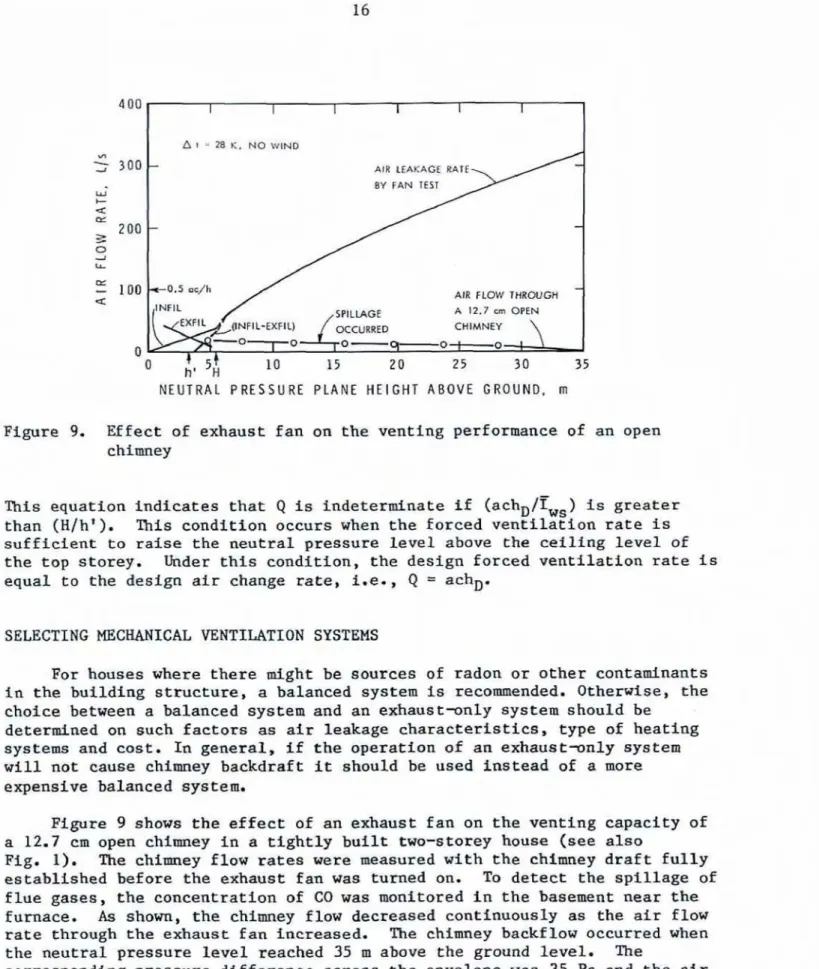
Figure 9. Effect of exhaust: fan on the venting performance of an open chimey
lrais equation indicates that Q is indaterminate if (achD/fwe) is greater than (Hlh'). lhis condition occurs when the forced ventilation rate is sufficient to raise the neutral pressure l e v e l above the ceiling l e v e l of
the top storey. Under t h i s condition, the design forced ventilation rate is equal t o the d e s i g n air change rate, i.e., Q = achD.
SELECTING MECHANICAL VENTIEATION SYSTEHS
For houses where there might be sources of radon or other contadnants
in the building structure, a balanced system is recommended. Otherwise, the
choice between a balanced system and an exhaustanly system should be determined on such factors as a i r leakage characteristics, type of heating systems and cost. In general, if the operation of an exhaust-only system will not cause chimney backdraft it should be used instead of a more expensive balanced system.
Figure 9 shows the effect of an exhaust fan on the venting capacity of a 12.7 cm open chimuey in a tightly built two-storey house (see also
F i g . 1). The chimney f l o w rates w e r e measured with the chimney draft f u l l y established before the exhaust fan w a s turned on. To detect the s p i l l a g e of flue gases, the concentration of CO was monitored in the basement near the furnace+ As shown, the chimney flow decreased continuously as the air flow rate through the exhaust fan increased. The chimney backflow occurred when
the neutral pressure level reached 35 m above the ground l e v e l . The
corresponding pressure difference across the envelope was 35 Pa and the a i r exhaust rate was 310 Lfs. The presence of CU w a s detected when the chimney f l o w had been reduced to a b w t 14 L / s . Tbis suggests that s p i l l a g e of the flue gas occurs well before the chirrmey flow is zero.
It should he pointed out that the cxhaus t fan was turned oa after the chimney d r a f t was fully e s t a b l i s h e d . If it was operating before the furnace
w a s on, the chimney would fill with the c o l d outdoor air and lose i t s draft. Under this condition, the chimney would continue t o back flow even though the exhaust fan flow drops to a value w e l l below what t a needed to initiate the back flow.
For housee w i t h chfnmeys, the stack effect reinforced by the a i r f l o w
through the chimey is usually lmch stronger than the wind effect during the winter months [31. The backflow w i l l not likely occur as long as the
neutral pressure level is below the ceiling l e v e l of the top storey. The c e i l i n g l e v e l , therefore, would be a reasonable choice as the limit for
sstisfactary chimuey startup.
With the limit for satisfactory chimep startup established, the interaction between an exhaust-only system and a chimep can be determined
using an air f l o w vs neutral pressure level graph similar t o Fig. 1. Such a graph can be constructed for any housee If
,
:
I
h t , n and 3 are known. Notethat :1 and h t are the a i r infiltration rate and the neutral pressure l e v e l of the house without chimneys or exhaust fans. For existing houses, these
parameters can be measured. For houses under construction, the values of
h' and n are normally assumzd to be H i 2 and 0.65 respectively. The value of 1: can be obtained from Fig. 3. To construct such a graph a reference point A representing I$ is plotted on a graph with a i r f l o w rate as the
ordinate and neutral pressure level as the abscissa. The air infiltration
l i n e is p l o t t e d next by drawing a straight line through A and the origLn, and extending it t o EI. Since at h r a i r infiltration rate is equal t o a t r e d i l t r a t i o n rate, the emrfiltration line should a l s o go through Point A. To
f i n d another point on the exfiltration line, a value for h between h' and H is selected and the air exhaust rate correspondgng to b 5s calculated f r o m the equation b a l m . Tfiis equation w a s obtained from Eq, (A8) by replacing
qs
with Igt for no wind conditions:The e d i l t r a t i o n rate corresponding t o h (Point 8) is then obtained by subtracting Q from the air infiltration rate. The exfiltration line is obtained by connecting a stralght line through A and B. And a liae
representing 'infiltration
-
exfiltration' can also he determined. If thehouse has a chfmuey the neutral pressure level correspcmdfng t o the chimney can be calculated' from Eq. (16). Finally, a horizontal line representing achD is p l o t t e d
on
the graph. Howif
the achDline
intercepts theinfiltration line below H, the chimney will start to vent when the furnace starts. On .the other hand, if t h e achD l i n e intercepts the infiltration line above H, chimney backdraft w i l l occur,
Two such graphs are shown on F i g . 10, one for a tight house and the other an average house. The values of
LE
w e r e 0.15 and 0.3 aclhrespectfvely. The values of h m and n are a s s m d t o be 2.7 m and 0.65
respectively. The results indicate that an exhaust-only system works
satisfactorily in an 'averaget house with an open chimney but it w f l l cause
chimney backdraft in a tight house unless an outdoor air supply is provided
L a the envelope. On the other hand, the operation of an exhaust fan will significantly reduce the amount of inside a i r leaving the house through the walls and ceiling. If a house has no chimney (egg., an electrically heated house) an e h u s t - o n l y system w f l l , also be satisfactory and will reduce the
-
f \ OPatATlNG U 0 . 1 - UNE 8F-
CHIMNEY H I I I L 1 5= 0. 6 I I I 1 n AVEWLAGE HOUSE1
0 . 6-
I I I I 1 I ' I-
J Y :1 = 0.3 w l h , n = 0.65 0 . 5-
4 EXf LLTMTION THROUGH 0. 3 INF 3lTRATION 0 . 1-
0 . 5 ENVELOPE = X OPERATING 1lNE OF d o EXHAUST F A N5
*
1 EXHAUST FANI
NEUTRAL P R E S S U R E PLANE H E l G H T A B O V E GROUND, m
Figure 10. Air flow versus neutral pressure l e v e l diagram f o r selecting ventflation systems
Equation 9 gives the air infzltration rate due to the combined action of stack effect and wind,
It
has been checked using the measured air i n f i l t r a t i o n rates of two bungalows with oil furnaces (T1 and TZ) 181. Figure 11 compares the estimated and oeasured air infiltration rates. The results indicate that except for three points, a l l the data lie within f25Z of the line of agreement, To determine statistically i f there is any0. 8 I I 1 I LINE O F AGREEMENT 0 . 7 - 0 . 6 - 0 . 5 - 0 . 4
-
0 . 3-
-
d-
0 0.1 0 . 2 0 - 3 0 - 4 0.5 0 . 6 0.7 0 . 8 ( I ~ ~ ) M E A S U R E D ' a c l hFigure 11. Gmparison of calculated and measured air infiltration r a t e s for houses T1 and T2
1. 0 O
m- . o o MEAN --
-0.4 a S T D . DEV. = 0.1535
Figure 12. Relative error versus measured a i r infiltration rates for houses T1 and T2
systematic difference between the c a l c u l a t e d and measured a i r tnfiltration rates, the data have been transformedto the form,
RE = (calculated value
-
measured value)/
measured valueFigure 12 shows the relative error, EtE, as a function af the measured a i r infiltration rate. The mean value of RE i s 0.037 and the standard deviation is 0.153. A student 't' test (t value is 0.24) indicates that the difference berween the mean and the ideal man of 0 is nut statistically significant, In other words, there is no systematic difference hetween the calculated values given by Eq. 9 and the measured air infiltration rates for the two houses.
S i d i a r comparisons have been made in Figs. 13 and 14 for the two
balanced systems and the two exhaustwnly system. Figure 13 shows that the agreement' between the calculated and measured air change rates is withtn f20% of the line of agreement for the balanced system. The agreement for the exhaust only -system Xs 215% {Fig, 14). Again there is no systematic difference between the calculat.ed and the measured air change rates.
A s i m p l e calculation procedure has been proposed f o r estimating the air change rate of a house u i t h or without mechantcal ventilation. This
procedure can be s ~ r i e e d as follows.
I) Prepare input data, C, a, A, V, h a , h, Tt, To, W and Q where C and n
can be measured directly or estimated from Table I ; A and V can be measured d i r e c t l y or estimated from the blue prints, hl,
h
and Q canalso be measured or estimated using the merhad given in Appendices A and B. To, Ti and W can be o b t a i n e d from meteorological records for the
area.
(ii) Calculate the
air
i n f i l t r a t i o n rate due t o stack effect alone from the equations:Wfth Chimney
0 . 7 - S Y S T E M I o S Y S T E M
JI
,=
0.6 - 1 U m - 0 . 5 - n W C u A 0 . 4 - 3 - U J 4: u 0.3 --
- m c u m 0 . 2 --
LINE O F AGREEMENT - - 0 0 . 1 0 . 2 0 . 3 0 . 4 0.5 0.6 0 . 7 0 . 8 ( a c h ~ ' a c l h ~ ~ ~ ~ ~ ~ ~ ~ 'Figure 13. Comparison of calculated and measured a i r change rates for systems I and I1
S Y S T E M III
o S Y S T E M
IP
Figure 14. Comparison of calculated and measured a i r change rates for systems I11 and IV
(iii) Calculate the a i r inffltration rate due to wind alone from the equations: Exposed Shielded Exposed S h i e l d e d
<iv) Calculate the air infiltration rate due t o t h e combined action of
stack effect and wind from the equation:
where:
(v) Calculate the a i r change rate due to the combined action of a i r infiltration and mechanical ventilation from the equations:
and Exhaus t-Only Systems:
+ ) Far h C 1
achE = F (
ISp
=
Q
h > BThe proposed method has been checked against measured afr change
rates. The agreement, ia general, was within 25% of t h e measured values. In addition, the foll&ng,two equations are proposed for sizing mechanical ventilation systems for houses.
Balaneed Systems: Q
=
(acbAh-
Exhaust-hly Systems :Q =
Ls
({
[ ( H h r )-I] ( a ~ h ~ / r = ) } ~ - ' - I ( u h ' )-
( a c h D / k )1")
where:G,
= 4.5 C {A/V)REFERENCES
I. S a w , C.Y. and Tamura, G.T., "Mark XI Energy Besearch Project:
Airtightness and Air l n f l l t r a t i o n Measurements", Dfvision of Building Research, HRCC, BR Note 162, 1980.
2. Shaw, C.Y., "A Correlation Between Air I n f i l t r a t i o n and Urtightness for Houses in a Developed Residential Area", ASH= Transactions,
V o l . 87, Part 2, 1981.
3. Shaw, C.Y. and Brown,
W.C.,
"Effect of a Gas Furnace Chimney on the Air k a k a g e Characteristic of a Two-Storey Detached House", Proceedings,3rd AIC Cwference, bndon, U.K., 1982.
4. Shaw, C.P., "The Effect of Mechanical Ventilatfan on t h e Air Leakage Characteristic of a Two-Storey Detached Houee", Dtvfsion of Building Research, WRCC, BR Mote 204, 1983.
5, ASILRdE Handbook, " F u n d ~ n t a l s " , 1981,
6. Beach, R.K., "Relative Tightness of New Housing in the Ottawa Area", Division of Building Research, WBCC, BR Note 169, 1979.
7. Dumont, R.S,, Orr, H.W. and Ffgley, D.A., "Airtightness ~asuremeuts of Detached b u s e s in the Saskaroon Area", M v i s i a d of Building Research,
NICCC, BE Note 178, 1981.
8. Tamura, G.T., "The Calculation of House Infiltration Rates", ASHRAE Transactions, Vol. 85, Part '1, 1979.
9, b n l e y , P.J., Helmeste,
R.H.
and Tamara, G.T., "6antaminants Buildup in Houses", Proceedings, 5th AIC Codereme, Weno, Nevada, USA, 1984-10, S i d e n , F. W,
,
" W i d , Temperature and Hatural, Ventilation: Theoretical Coasiderations", Energy . a d Buildings, V a l , 1, Nu, 3, 1978.11. Sherman,
M.H.
and Grfmrud,D.T.,
"Heasarement of Infiltration Using Fan Pressurization and Weather Data", Proceedfngs, 1st A I C Conference, Berkahire, UK, 1980.12. ASHIRAE Standard 62 1981, "Ventilation for Acceptable Indoor Air Quality", 1981.
13. Shaw, C.Y. and Kim, A., "Performance of Passive Ventilation Systems in a Two-Storey House", Proceedings, 5th AIC Conference, Reno, Nevada, USA, 1984,
APPENDIX A
ESTIMATION OF NEUTRAL PRXSSURE LEVEL FOR HOUSES WITH CHIMNEYS OR EXHAUST DEVICES
a p;
-
NmTRAL PRESWRE LEVEL WITH CfllMHEY OR FAN
2 n d FLOOR NEUTRAL fXESSURE LEVEL
WITHOUT C H I W E Y OR FAN I r t FLOOR -- - - - I I///// - 6 - 4 - 2 0 2 4 6 A P . P R E S S U R E D l # F E R E H C E , Pa K b t K , ' C ' A
-
Figure A l . Distribution of leakage openings and pressure difference profile caused by temperature difference
If a house has a chimney or an exhaustanly ventilation system, the neutral pressure l e v e l , as shown in Fig. A l , w i l l s h i f t from h t t o h
.
The vertical distribution of pressure difference across the exterior wall due to stack effect alone will change accordingly. Assuming that for a house with neither ch3mney nor exhaust fan (i) the air leakage charactertstic can be represented by two openings, one located at the grade level and the other at the ceiling level of the top storey, and (ii) the v e r t i c a l distribution af pressure difference isknown,
h can be estimated from the conservation ofmS8 [1.3]:
%
( ~ ~ = ~Ka ( A ~ ~ ) ~ ) ~ p i p + ~Ebi
(All
Substituting the following relationships (from Fig. A l ) into Eq. ( A l l : APb = (h / h t ) APL
,
AP, = [ ( B
-
h)/(H -h')] AP; = [(H/ht)-
(h/hW)]APbh
Q
F i g u r e A2,
-
versus-
hl
t,
In the above equation, the terms Ka and
K,,
define t h e a i r leakagecharacteristic of the house without either chimney or exhaust device. They
can be estfmated f r o m the mass balance equations [ 1 3 ] :
and
C*A = Kb
+
K, (A41where C is the f l o w coefficient without chimneys ox exhaust f a n . Since:
AP; = [ ( H
-
h')/hl]AP{ therefore,a.
(A31 can be rewritten as:Kb = K,[(H
-
h')/hfI " ( P ~ / P , )
Substituting Eq. (A5) i n t o Eq, (AZ), w e have:Eguation (A6) can be solved for h/h' and H/h' as follows. (i) Existing Houses
The values of C, APL, h f and n can be measured and K, can be estimated
from E q s . (Ah) and (AS). The only unknown on the left hand s i d e of E q . ( A 6 1
Appendix 8). The value of M for a chlmney can be estimated using the method
given in the ASHRAE Handbook 114.J.
With all the variables on the left hand side of Eq. (A6) known, the value of (h/hl) can be obtained by graphical methods. Figure A2 shows a t y p i c a l plot of ( h f h t ) vs M / [ K ~ ( A ~ ) ] " for n = 0.65 and various values of H/hB. Similar p l o t s can be constructed f a r other values of
n.
(ii) b u s e s Dnder Design
For houses under design, the values of n and h' are usually assumed t o
be 0.65 and E l 2 respectively. The fbllowing approxinsitirrns would also
a p p l y
and
Replacing M with Q (i.e., converting the unit of M from L / s t o ac/h), Eq. (A6) becomes:
APPENDIX B
FORCED VENTILATION
RATE
OF AM EXHAUST-ONLY SYSTEM FOR WINTER MONTHSThe design exhaust a i r flow rate for winter operation can be estimated from Eq. (A6):
To s o l v e for M, one has to know (h/hl) and K.(AP~)". These two terms can be estimated as follows,
Consider a house with an average air i n f i l t r a t i o n rate of
,
,
i
for t h e winter months. The neutral pressure level is h'. If an exhaust-only s y s t e m is i n s t a l l e d , the neutral pressure level will rise to h. If the v e n t i l a t i o n system is properly sized, the amount of outdoor air entering into the house should be equal to achD, the design ventilation rate. As shown in F i g . ba, the outdoor a i r supply rate is approximately proportional to the neutral pressure level. Thus:noting that
Substftuting Eqs. ( B l ) and ( A 9 ) into Eq. ( A 6 ) and replacing M with Q ( i . e . , converting the unit of M f r o m L/s to ac/h), we have


![Figure 3 shows : I a s a function of C at At*=20 K for houses with and without chimneys [ 2 , 3 , 9 ]](https://thumb-eu.123doks.com/thumbv2/123doknet/14296430.493358/11.918.97.844.119.1182/figure-shows-i-function-c-k-houses-chimneys.webp)
![Figure 4 shows the measured air infiltration rates as a function of wind speed for both exposed and shielded conditions [ Z ]](https://thumb-eu.123doks.com/thumbv2/123doknet/14296430.493358/12.936.63.882.154.1170/figure-shows-measured-infiltration-function-exposed-shielded-conditions.webp)


![Figure 6. Tatal air change rate and pressure difference profile of balanced systems [ 4 ]](https://thumb-eu.123doks.com/thumbv2/123doknet/14296430.493358/16.930.48.913.66.1138/figure-tatal-change-pressure-difference-profile-balanced-systems.webp)