HAL Id: hal-02127309
https://hal.archives-ouvertes.fr/hal-02127309
Submitted on 15 May 2019
HAL is a multi-disciplinary open access archive for the deposit and dissemination of sci-entific research documents, whether they are pub-lished or not. The documents may come from teaching and research institutions in France or abroad, or from public or private research centers.
L’archive ouverte pluridisciplinaire HAL, est destinée au dépôt et à la diffusion de documents scientifiques de niveau recherche, publiés ou non, émanant des établissements d’enseignement et de recherche français ou étrangers, des laboratoires publics ou privés.
Aluminium Alloy and Coatings: Historical and
Materials Science Approach
Magali Brunet, Audrey Cochard, Christophe Deshayes, Chantal
Brouca-Cabarrecq, Luc Robbiola, Jean-Marc Olivier, Philippe Sciau
To cite this version:
Magali Brunet, Audrey Cochard, Christophe Deshayes, Chantal Brouca-Cabarrecq, Luc Robbiola, et al.. Study of Post-World War II French Aeronautical Aluminium Alloy and Coatings: Histor-ical and Materials Science Approach. Studies in Conservation, Maney Publishing, 2019, pp.1-15. �10.1080/00393630.2019.1610846�. �hal-02127309�
Study of post-World War II French aeronautical aluminium alloy
and coatings: historical and materials science approach.
Magali Bruneta*, Audrey Cocharda, Christophe Deshayesa, Chantal Brouca-Cabarrecqa, Luc Robbiolab, Jean-Marc Olivierc, Philippe Sciaua
a CEMES CNRS, Université de Toulouse, 29 rue Jeanne Marvig, 31055 Toulouse-France b TRACES UT2J CNRS, Université de Toulouse, Maison de la Recherche, 31058
Toulouse-France
3 FRAMESPA UT2J CNRS, Université de Toulouse, Maison de la Recherche, 31058
Toulouse-France
Abstract
In many countries, collections of ancient aircraft, conserved in Air and Space museums or local associations, reflect the importance of a national or local history. Mostly parked outdoor, aircraft suffer from important corrosion requiring
conservation operations. During renovation, metallic parts are often replaced by association members. This can lead to a major loss of information since industrial archives dealing with materials and processes were not necessarily conserved. However, if these elements can be considered, they could be a fundamental source of information on the materials originally used and of the technical history of aeronautics. This work reports a thorough study of aluminium-based alloys parts collected on a Breguet aeroplane dating from the 1950s, during its recent
renovation. Thanks to an approach coupling multi-scale material characterisation and researches in archives, information on the industrial know-hows are revealed. Several historic grades of aluminium-based alloys were found, namely U4G, A-U4G1 and A-U3G, depending on the role of the part. Similarly, different protective coatings were identified (anodic oxidation, primers and paintings), depending on the role of the metallic part and its location in the plane. The knowledge of the materials from bulk to the coated surface is necessary for a good conservation practice of the aeronautics heritage artefacts. Related documents and archives also help fundamentally the understanding of such complex cultural heritage systems. Keywords: aluminium alloys, aeronautical heritage, aeroplanes, coatings, conservation.
Introduction
Amongst markers of the industrialisation process, which started at the end of the 19th century and carried out throughout the 20th century, aeroplanes are one of the most emblematic. Motorized aeroplanes at the very beginning of the 20th century were the symbol of human adventure as for instance in the United States, the flight of the Wright brothers in 1903 (Orville Wright and Wilbur Wright September
1908, n°5) and in Western Europe, the flight over the Channel by Louis Blériot in 1909 (Fontaine 1909). But soon, aeronautics revolutionised transport of human and goods, armies, international trades and exchanges of all sorts (Chadeau 1987; Olivier 2014; Pattillo 1998). Preserving this history covers the preservation of aeronautical artefacts (aeroplanes, helicopters, flying machines …etc) and also intangible dimensions such as
memories, social aspects and industrial manufacturing know-hows (TICCIH 2011). On both aspects, tangible and intangible, the conservation of aeronautical heritage presents many challenges. Although Air and Space museums exist in most countries around the world, with dedicated covered sheds and with specific aircraft restoration procedures (Mikesh 2009), there is a large part of collections managed by local associations. And in most cases, aircraft are conserved outdoors, because of their size and their numbers. Some old aircraft consequently undergo severe corrosion. For ensuring security, major intervention on the aircraft can be required such as the replacement of corroded or mechanically damaged structural parts. Repainting the overall aircraft is most of the time, carried out at the end of the structural restoration. This is performed firstly, in order to protect the parts newly replaced and the original parts whose coating lost probably efficiency and secondly, because the association members want to exhibit a like-new appearance. During the parts removal and the repainting step, we assist in the major loss of historical information concerning materials and indirectly to industrial know-hows. Archives related to the manufacturing of the aircraft, where such information could be found, are most of the time difficult to find and fragmentary. Technical documents could be spread on different sites and thrown away when considered out of date or during the merging between two companies.
Considering all these factors, this highly specific cultural heritage is in danger. Information on raw materials used and processes has to be retrieved and contextualised in the same way it is done for works of art. The interests are manifold: for conservation purposes, the materials parts of old aircraft should be studied or at least identified well in advance to propose appropriate restoration protocols (Adams and Hallam 1991; Gayle and Goodway 1994; Guilminot and Tissier 2015; Rocca et al. 2010); for historical purposes then, historic materials reveal the technicity of a
country and indirectly the historical context in which they were produced. Specifically for aeroplanes, the technology is relatively recent and it experienced a tremendous development throughout the 20th century leading to fast evolution in terms of materials and processes. In particular, aluminium alloys enabled the development of lighter-than-air vehicles: Zeppelins and aeroplanes (Hardouin Duparc 2005; Starke Jr and Staley 1996). Correlating the evolution of materials with the historical context should highlight the synergy which existed in this field.
To do so, the restoration of an aircraft is a good opportunity to study thoroughly a representative industrial artefact, to understand its materiality and the manufacturing processes involved in its fabrication. It is the time when the structure of the aircraft is apparent and when materials are exposed, which allows to document an important part of the materials constitutive of the primary and secondary structures. On parts that are being removed (for replacement), scientific analysis can be carried out. A thorough research in all related documents such as industrial archives, when accessible, completes the understanding and the knowledge on the object.
In this article, through an
interdisciplinary approach coupling material investigation and archives analysis, we will show and discuss the extent of information which can be revealed from parts collected on an old aeroplane, information useful for the conservation of a specific industrial heritage and for history of techniques. We will illustrate our approach with the case of a French aeroplane built in the 1950s: the double-decker Breguet 765 Sahara n°504 65-PH. This aeroplane is nowadays being renovated at the association Les
Ailes Anciennes Toulouse. The case of the
Breguet 765 Sahara is a good example of the incomplete and dispersed archives due to politics and economics. Breguet enterprise was one of the most important aeronautical companies which developed, during the first
middle of the 20th century, numerous aeroplane models in Western Europe. After the merging of Breguet Company with Dassault Aviation group in 1971, some documents disappeared: either lost or destroyed (Audrey Cochard 2016). In this context, the analysis of the materials collected directly on the aeroplane allows to complete the understanding of the construction techniques as well as the context enlightening a part of the history of Breguet company. This study follows previous studies made on this aircraft: one focused on rivets (A. Cochard et al. 2013) and one comparing two aluminium alloys (A. Cochard et al.; 2017). Here, the methodology is extended to different parts collected on strategic areas of the aircraft: on the primary and secondary structures, exposed either inside or outside, on which a precise investigation is carried out covering the analysis of aluminium alloys but also the protective coatings, which haven’t been reported before. The purpose is to extend and define the common knowledge on French aeronautical alloys and protective coatings of the 1950s. Moreover, since standardisation in aeronautics industries started during and after World War II, first in each country and then internationally, the results obtained in this specific case are believed to be useful for a more global view on historic aeronautical materials.
Sampling strategy and experimental methods
Sampling strategy
Since several years, we are following the renovation of a big carrier airliner Breguet 765 Sahara n°504 64-PH, which is part of the aircraft collection exposed and conserved by the association Les Ailes Anciennes de Toulouse (France). The principal goal of this association
1 A long part with a constant section other than bars, rod, strip or sheet.
is to conserve and to highlight the aeronautical memory of the region: visitors are allowed to enter and admire the aircraft interior during the cockpit days organised several times a year. This collection reflects the aeronautic adventure and the local industrial history. The Breguet 765, a double-decker built in 1958 by the local industrial Louis Breguet for military usage (Audrey Cochard 2016), is one of the most valuable aeroplane of the collection. Due to budget drastic reduction, the purchase orders were reduced down to four aircraft by the French state in 1959 (Archive 1957). This aeroplane is thus a rare specimen.
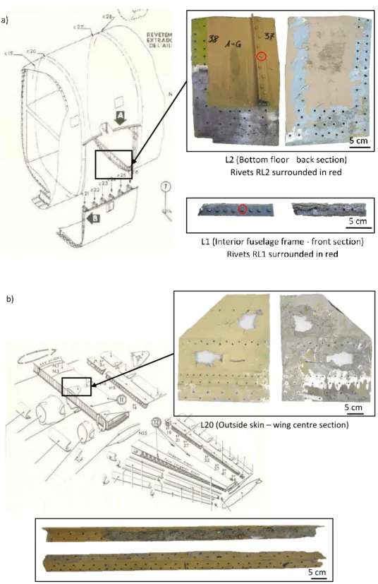
During the renovation of the Breguet 765, some partly corroded parts are removed by members of the association for replacement. For this study, representative parts were collected inside or outside the aircraft as shown in Figure 1 (Breguet n.d.):
Three plates (L2, L8, L20) with different roles and locations: L2 is from the primary structure, a reinforcement plate underneath the bottom floor inside; L8 is a cladding plate near the engine used as a flame shield and L20 is a plate from the upper surface of the wing centre section also called skin (thus an outside part);
Two structural parts: L9 is a lock bracket from inside the landing gear and L15 is a profile1 from the trailing edge of the wing centre section. Both these parts are very much stressed during the aircraft lifetime; Rivets previously studied (A. Cochard et
al. 2013) are included in the corpus for
comparison purposes between the different selected metallic parts. RL1, from a stringer (called L1) has a diameter of 4 mm and RL2 from the plate L2 has a diameter of 5 mm.
Figure 1. Photographs of collected parts (front and back side) from Breguet 765 airplane with localization on original plans (Breguet n.d.); a) Plate L2 (2 mm thick) with RL2 rivets (5 mm diameter) and profile L1 with RL1 rivets (4 mm diameter), b) Plate L20 (3 mm thick) and profile L15 (4 mm thick); c) Plate L8 (1.6 mm thick) and bracket L9 (5 mm thick).
L15 (Trailing edge – wing centre section)
L20 (Outside skin – wing centre section) 5 cm
5 cm b)
(Figure 1. Continued)
Material analysis
After this collection step, multi-scale characterisation were conducted to determine the nature of the original alloys together with their coatings taking into account their alterations. Practically for each collected part, this was carried out to cover all aspects: the composition and the microstructure of the bulk material (aluminium alloy), and the nature and stratigraphy of the surface (protection coating). The observation by optical microscopy (OM) of cross sections allowed a more in-depth study of the bulk alloy as well as the coating stratigraphy on both sides of each metallic selected part. Scanning Electron Microscopy (SEM) on a FEI Helios Nanolab 600i operating at 20 kV coupled with Energy Dispersive X-Ray Spectroscopy (EDS), an Oxford X-MaxN 150 spectrometer, was used for alloy elemental composition, intermetallic precipitates composition and coatings composition at the microscale.
Compared with our previous results in articles (A. Cochard et al. 2013; A. Cochard et al.; 2017) where inductively coupled plasma optical emission spectroscopy (OES) and wavelength dispersive X-ray spectroscopy (WDS) were used to determine alloys elemental composition, we favoured here SEM-EDS which is accurate enough for differentiating alloys grades. For each alloy, EDS acquisition was performed on four areas of 500x500 µm² with a minimum of 100 000 counts on each spectrum. Before each measurement, the optimisation of the beam intensity was carried out on pure Co standard. Quantitative analysis was performed with internal standards (pure K-line Al, Si and Fe standards). Results were normalised to 100 wt.%.
Both observation techniques (OM and SEM) required a sample preparation which consists in cutting the parts according to the three principal orientations, giving rise to three principle planes: expected rolling plane, transverse plane and normal plane; then in embedding the
L8 (Flame shield – engine nacelle)
L9 (Lock bracket - landing gear) 5 cm
5 cm c)
specimen in an epoxy resin and mechanically polishing it on water-lubricated abrasive papers (silicon carbide) of decreasing granulometry: from 600 to 1200 paper grades. Samples were eventually polished on cloths with diamond abrasive pastes with 3 µm particle size and 1 µm particle size, to obtain a mirror aspect. A Keller's solution (HF 1 ml, HNO3 2.5 ml, HCl 1.5 ml in demineralized H2O 95 ml) was used to reveal the microstructure of the alloys.
As aluminium alloys are structural hardening alloys here, transmission electronic microscopy observations with elemental analysis (TEM-EDS) were carried out to study the microstructure at the nanoscale, i.e. identify dispersoïds and hardening precipitates. In this case, specimen preparation was the following: after mechanical polishing up to 2400 SiC paper grade, in order to obtain a thickness of 25 µm, the specimens were then electrochemically thinned using a Tenupol-5 Struers apparatus operating at 60V in a solution of methanol and nitric acid (3:1) at -15°C. The nanostructure was observed using a Transmission Electron Microscopy (TEM) JEOL 2010 operating at 200kV.
As regards the identification of protective coating constituents, XRD was performed with a Bruker D8 Discover equipped with a micro-source Co and a 2D detector.
Archives research and analysis
In parallel, research was performed in the archives of Breguet enterprise which were dispersed in the 1970s and are now partly conserved in different sites: at the Institute for History of Aluminium (IHA, Paris), at the archives centre of the Historical Service for Defence (SHD, Châtellerault), at the documentation centre of the Air and Space museum Paris-Le Bourget and at the association
Les Ailes Anciennes Toulouse. Other sources
2
André Sunez, a member of Les Ailes Anciennes, former trainer at the Air Army school in Rochefort, provided us with documents on coatings and protection against
were employed such as metallurgical journals of that time: la Revue de l’Aluminium or
l’Aluminium Français, as well as private
archives2. Even though archives may be lacunar, it allows to collect some information on the materials, the manufacturing processes and on the aircraft itself and to relate them to the measured data on materials.
Two documents belonging to Breguet company provided very useful information on aeronautical materials: the standard from the factory of Vélizy (Breguet 1946-1954), containing forms edited from 1946 up to December 1954, and the standard from the factory of Anglet (Breguet 1951-1959) with forms edited from 1951 up to 1959. This latter document concerns exclusively the Breguet 761 to 765, Breguet 960 and 1050. It is important to mention that not all the pages of the standards were recovered.
Aluminium alloys
Results of material analysis
The alloy composition of the different collected parts, measured by SEM-EDS, is given Table 1. All alloys are Al-Cu-Mg belonging to the Duralumin family. Duralumin, discovered by Alfred Wilm in 1906 (Hardouin Duparc 2005) and produced industrially in Germany from 1910, is an aluminium alloy containing originally copper, manganese, to which magnesium was added. Thanks to alloying with copper, magnesium and thanks to appropriate thermomechanical and ageing treatments inducing nanoprecipitation of specific Al-phases, high strength materials were obtained (Hornbogen 2001). Different alloy grades were quickly developed by nations for aircraft and zeppelins construction at the beginning of the 20th century and produced under specific
corrosion from Aérospatial, SNCAN and Dassault Aviations just after merging with Breguet company in 1971.
classification. In France, they were named A-U4G, A-U4G1, A-G3… etc according to the alphanumeric classification 3 adopted at the beginning of the 1940s (Lebouteux 1956) and followed by the AIR 3350/C aeronautical standard of 1957 (AIR3350/C 1957):
From Table 1, two alloys are identified: A-U4G1 for L2, L9, L15 and L20 parts, A-U4G for L8 and RL2. The main difference between A-U4G and A-U4G1 concerns the magnesium and silicon concentrations: a higher concentration of magnesium for A-U4G1 (Mg around 1.5 wt.%) than for A-U4G (Mg less than 1 wt.%) and silicon (about 0.6 wt.%) intentionally added in A-U4G.
One of the rivet alloy (RL1) was found with a different composition: less Cu (around 3 wt.% compared with the 4 wt.% for U4G and A-U4G1) and less magnesium and manganese. It was identified as an A-U3G. The precise elemental composition of this ancient alloy was found in an article from Tournaire and Renouard4 published in 1956 (Tournaire and Renouard 1956).
Micro-alloying and thermomechanical
treatments control the mechanical properties of aluminium alloys (Polmear 2005a). Observing the microstructural features, i.e. grain size and shape, intermetallic precipitations at all scales, can reveal important information on the alloys mechanical and chemical behaviour. In particular, according to the Hall-Petch law (Hall 1951), the grain size contributes partly to the hardening of the alloy: the smaller the grain size is, the higher the yield strength of the alloy. Figure 2 shows metallographic structure of the studied parts, from optical microscopy performed after a Keller metallographic attack. Grains of the different alloys are this way revealed. Full report of metallographic structures for L2 (Figure 2a) and L8 (Figure 2b) can be found in previous publication (A.
3 A for aluminium, U for copper and G for magnesium followed by the nominal content in wt.%.
Cochard et al. 2017). Here, only one orientation (normal plane) is shown and commented. L2, L8 and L20 plates (Figures 2.a.b.c) show grains with a preferential orientation (anisotropy in shape). The size and the shape of the grain depends mainly on the manufacturing process, in particular the thermomechanical treatments applied. For the plates, the preferential orientation is the signature of a rolling process followed by recrystallization steps. L20 (Figure 2.c) exhibits longer grains (average length equal to 117 ± 19 µm) than L2 (69 ± 35 µm) and L8 (46 ± 15 µm). As the three plates don’t have the same thickness (3 mm, 2 mm and 1.6 mm respectively), they probably received different number of rolling passes and/or different recrystallization treatments leading to different grain size and shape.
Bracket L9 (Figure 2.d) and profile L15 (Figure 2.e) have also a microstructure with preferential orientation but grains are very long, thin and crushed. This specific microstructure is produced during extrusion generating severe plastic deformation (Hérenguel and Lelong 1958). For rivets RL1 (Figure 2.f) and RL2 (Figure 2.g), grains are equiaxed. Rivets were also fabricated by extrusion but a heat treatment for recrystallization generally was done before the formation of the head (Penel 1950) which transformed the grains shape. Furthermore, it is observed that A-U3G rivets have larger grains (average diameter equal to 47 ± 25 µm) than A-U4G rivets (average diameter equal to 29 ± 15 µm) (A. Cochard et al. 2013). This particular point will be discussed below after a deeper look at the precipitation at the nanoscale. Overall, the microstructures of the two rivets are comparable with those reported in 1955 for similar rivets (Tournaire and Renouard 1956).
4 Respectively head of Researches and Laboratories and head of Researches of the factory Issoire, General Company of Duralumin and Copper.
Al Cu Mg Mn Si Fe Ti Corresponding alloy L2 92.85 ±0.26 4.83 ±0.16 1.30 ±0.06 0.52±0.02 0.21±0.07 0.27±0.10 0.03±0.06 A-U4G1 L8 93.06±0.03 4.33±0.05 0.80±0.01 0.58±0.00 0.67±0.03 0.46±0.03 0.10±0.03 A-U4G L9 92.41±0.09 4.89±0.07 1.52±0.02 0.82±0.07 0.12±0.00 0.18±0.03 0.05±0.04 A-U4G1 L15 92.00±0.012 5.20±0.13 1.50±0.02 0.86±0.03 0.17±0.03 0.21±0.02 0.05±0.04 A-U4G1 L20 92.57±0.10 4.72±0.02 1.50±0.02 0.76±0.04 0.07±0.02 0.27±0.05 0.76±0.02 A-U4G1 Rivet RL1 95.08±0.11 3.65±0.08 0.30±0.07 ≤0.10±0.04 0.57±0.02 0.34±0.04 0.07±0.03 A-U3G Rivet RL2 93.79±0.18 4.23±0.07 0.51±0.06 0.64±0.04 0.51±0.05 0.24±0.03 0.08±0.03 A-U4G
Table 1. Elemental composition (wt%) of the collected parts measured by SEM-EDS. Last column is the alloy identification according to AIR 3350/C (AIR3350/C 1957)
In all the collected parts (plates, bracket, profile and rivets), particles in the micron range are observed (See Figure 2). These coarse particles (> 1µm) are intermetallic phases generally encountered in this type of Al-alloys (Hughes et al. 2013) (Mondolfo 1976). Analysed with EDS, particles in U4G and A-U4G1 alloys are composed of Al-Cu-Mn-Fe-Si, Al-Cu, Al-Cu-Mg and/or Al-Mg-Si. For the A-U3G alloy, only Al-Cu-Fe particles were found. Such coarse intermetallic particles are normally deleterious for mechanical properties: they can cause cracks as well as corrosion. It is thus, important to document them in terms of size and density for understanding the possible alteration of historic alloys.
At a higher scale, Figure 3 shows TEM images (Bright field) of the concerned alloys. One can see dispersoids, particles of about ten
nanometres to a few hundred nanometres and homogeneously distributed. Formed during the homogenisation heat treatment and always containing manganese in Duralumin, the dispersoids are partly responsible for the hardness of the material by limiting the size of the grains in the alloy. In A-U4G1, the dispersoids are rod-shaped (Figure 3.a L2 plate) and their composition is AlCuMn, whereas in A-U4G, their forms are ovoid (Figure 3.b L8 plate and 3.d RL2 rivet) with AlMnSi composition. In A-U3G, there is hardly any dispersoids (Figure 3.c RL1 rivet) due to the absence of manganese in the alloy composition. This explains the larger grain size in this rivet observed in Figure 2.f.
Figure 2. Optical microscopy images after Keller etching of collected parts in the plane normal to the rolling direction. a) L2 (A-U4G1), b) L8 (A-U4G), c) L20 (A-U4G1), d) L9 (A-U4G1), e) L15 (A-U4G1), f) RL1 (A-U3G), g) RL2 (A-U4G). For the rivets, the images were acquired in the shank. ND: normal direction / RD: rolling direction.
Figure 3. Observations by TEM of dispersoids in top row (bright field observation): a) plate L2 (A-U4G1), b) plate L8 (A-U4G), c) rivet RL1 (A-U3G) and d) rivet RL2 (A-U4G).
Above all, the particularity of these aluminium alloys is to induce nanoprecipitation during the ageing step after solution heat treatment and quenching, which markedly enhance their strength by preventing the movement of the dislocations (Starink et al. 2004) (Silcock et al. 1954). As demonstrated in our previous work (A. Cochard et al. 2017) for two alloys, A-U4G and A-U4G1, the microstructures revealed by TEM in conventional mode are typical of an ageing at room temperature corresponding to a treatment T4 (Polmear 2005b).
5 "Fiche Standard Br. 201, feuille 1, 1956 – from Standard Forms, Anglet Factory (Breguet. 1951-1959).
Results of archives analysis
Information on materials is scattered in several documents of the Breguet Company. In the Anglet standard (Breguet 1951-1959)5, amongst other alloys, are listed all the aluminium alloys employed for the fabrication of plates, profiles, rivets together with some information on thermomechanical treatments and minimum required mechanical properties. For plates in A-U4G and A-A-U4G1, a heat treatment at 495°C was applied on the metallic element and was followed by ageing at room temperature for 4 days, corresponding to a treatment T4. In terms of mechanical properties, A-U4G1 shows an
1 µm 1 µm
1 µm 1 µm
a) b)
ultimate strength of 50.5 kg/mm² (495 MPa), a yield strength of 32 kg/mm² (314 MPa)) and a hardness of 110 HB significantly higher than the values for A-U4G (respectively 45 kg/mm² (441 MPa), 27 kg/mm² (265 MPa) and 100 HB).
In another document, the technical clauses for Breguet 765 aircraft (Breguet 1956), the typical usage of each of these two alloys in the aircraft is specified: A-U4G constitutes the fuselage with its reinforcement frame, stringers and all non-structural parts whereas A-U4G1 is employed for high resistance profiles. Particularly for the Breguet 765, as the aircraft was dedicated to the transport of heavy loads, an adaptation was made: the skin and stringers of the wings originally in A-U4G were changed to A-U4G1.
About rivets, in the standard of Vélizy (Breguet 1946-1954) 6, a hand-written note mentions the fact that all rivets A-U4G should be replaced by rivets A-U3G. In the more recent standard of Anglet (Breguet 1951-1959) a new recommendation was done by the constructor7: A-U3G was to be used only for rivets with diameters ≤ 5 mm until stocks were exhausted and only if cutting resistance was at least 25 kgf/mm² (245 MPa).
Discussion : Laboratory analysis and archives
Cross-referencing Breguet’s archives, scientific knowledge in the 1950s and laboratory analysis was necessary to understand and verify the choices of the constructor on this specific aircraft. The choice of the aluminium alloy to be employed for the fuselage, the stringers or the rivets was driven by the required mechanical properties but, as seen in the Breguet standards, evolution in the decision of using such or such alloy could intervene.
6 Adjonctions et modifications au standard Breguet, Br 411 « Rivets en AU4G et 35NC6f », Décembre 1954 – from Standard Forms, Vélizy Factory (Breguet. 1946-1954).
At the time of the Breguet Sahara construction, the role of magnesium in hardening had been evaluated empirically (Chevigny 1954). It was known that addition of Mg up to 1.5 wt% was beneficial for the mechanical properties. That is why A-U4G1 was introduced in the aeronautical industries for high resistance parts. Analysis of the collected parts confirms the usage of A-U4G1 for the airfoil (L20) as well as parts requiring a high resistance (bracket L9 and profile L15). On the other hand, A-U4G was used in cladding parts (such as L8). However, analysis showed that L2, a vertical reinforcement plate placed underneath the floor is actually made out of A-U4G1 which contradicts the clauses specifying that the frame of the fuselage and the floor should be in A-U4G. Although not mentioned in the technical clauses, the plates reinforcing the floor may have been changed to A-U4G1 because of heavy loads to be carried on this aircraft, similarly to the wings case.
For the rivets of the Breguet 765, two types of alloys were identified by the scientific analysis: A-U4G and A-U3G. The diameters of these rivets were measured to be 4 mm for RL1 (A-U3G) and 5 mm for RL2 (A-U4G) in accordance to the recommendation made by Breguet Company. Now, to understand why this specific alloy composition had been applied here, it is necessary to explore the historical context. To start with, rivets play a strategic role in aircraft construction, as they constitute the basis of the aircraft assembly and insure its good mounting. Highly demanding properties are thus required for rivets and aluminium alloys were specifically developed to meet the requirements. In their article from 1956 (Tournaire and Renouard 1956), Tournaire and Renouard talked about the necessity of simplifying riveting. A-U4G traditionally used
7 Form « Rivets AU3G et 35 NC6f », Br 411/416, Juin 1957 – from Standard Forms, Anglet Factory (Breguet. 1951-1959).
for rivets, because of its good cutting resistance (26 kgf/mm² minimum), had a limited period (about 8 hours) after quenching for being placed, after which it became too hard. When rivets became too hard, they had to be heat treated again (solution treatment followed by quenching into water). To avoid this problem, A-U2G alloy, containing only 2 wt.% of copper and less than 1wt.% of Mg was developed. Although this new alloy didn’t suffer from premature ageing, the cutting resistance was reduced down to 22-24 kgf/mm². Eventually, A-U3G with 3 wt.% of copper and less than 1 wt.% of magnesium was developed in 1943. This alloy, only studied in 1954 consists in a compromise between A-U4G and A-U2G: it didn’t have a limited period for riveting and it exhibited a guaranteed cutting resistance of 24 kgf/mm², with the possibility to reach 26 kgf/mm² after 3 months at 25°C. Hopes for a better cutting resistance were strong in the industry and this new alloy was authorized by the French Aeronautics Industry. Breguet Company followed the development of this new alloy and decided to implement it in December 1954 in the Breguet 765 as the standard from Vélizy testifies. However, due to the limit in cutting resistance of this new alloy, the constructor decided eventually to limit its use to rivets with a diameter less than 5 mm in diameter. Laboratory analysis prove here that the standard of 1957 (Anglet) is the one which was applied to this particular aircraft.
Protective coatings
From the early stages of the development of aluminium alloys, corrosion of aeronautical parts has been an issue (Pubellier 1931). Protective coatings of all sorts were developed throughout the 20th century up to now. Generally constituted of several layers with different chemical nature (mineral or organic), the choice of the protective coating applied on a
8 Aluminum Company of America
part depends on its role, its location (inside or outside, accessible or not for future maintenance operations) and the type of environment the aeroplane would experience (marine or land). Cost issues intervene as well in the choices. Previous work identifying coatings thanks to analysis on WWII aeroplanes (American, German and Japanese) and thanks to a thorough research of historical documents was carried out by Adams and Hallam (Adams and Hallam 1991). This work as well as technico-scientific documents produced in the 1950s in France (Meynis de Paulin Novembre 1947; Octobre 1947; Rousset-Bert 1958) helped understanding the several options that constructors had in hand for the protection of structures in light metals in aeronautical construction. These main protective treatments were :
Cladding with a more electronegative metal to prevent electrolyte from reaching the bulk alloy and to insure cathodic protection. Alclad where high purity aluminium is cladded on the alloy, was developed by AlCoA8 in 1927 in the USA (Dix August 1927). The product was known in France under the name Vedal (Bailly 1936).
Anodic oxidation where alumina between 5 and 25 µm thick is formed electrochemically. As reported by (Adams and Hallam 1991), different processes were developed worldwide as soon as 1927 based on: chromic acid baths (in Great Britain, the well-known “Bengough-Stuart” process, in the USA), sulphuric acid baths (GB, USA) and oxalic acid baths (mainly in Japan and Germany). In France, the most employed electrolytic baths in the 1950s were the ones with chromic acid, sulfuric acid or BF4 process (Rousset-Bert 1958). The BF4 process was a mixture of chromic, oxalic and boric acids.
Chemical oxidation where an oxide layer is grown in boiling water or in an alkaline bath containing chromates and/or phosphates. The first process was developed by Bauer-Vogel in Germany in 1916 and modified in 1923 (Modified Bauer-Vogel process): it is based on boiling bath of potassium carbonate, sodium bicarbonate and potassium bichromate. Many other processes were developed between the 1930 and 1945.
Chemical conversion coatings in acid baths. In this category, a particular process developed in 1945 in the USA called Alocrom (Spruance 1945) was soon employed in France under the name Alodine (Hess 1951). It consists in a mixture of mineral acids, phosphoric acid mainly, with metallic salts containing chromium cations and fluoride anions. The resulting coating is essentially composed of amorphous metallic phosphates.
Primers: a layer usually in contact with the naked metal, whose role is to be anodic thanks to the use of pigments inhibitors of corrosion (Raison 1979) and to provide adhesion properties for the paint layers. Different types of primers were developed in most countries: primers using zinc chromates and later phosphate primers. In France, widely used in the 1940s was a complex zinc-chromate and potassium zinc-chromate written under the formula (K2O, 4ZnO, 4 CrO3, 3 H2O) (Meynis de Paulin Novembre 1947). Based on this knowledge, the objective here was to understand the applied protective coatings on the Breguet Sahara and to confront the material analysis to the recommendations defined by the constructor’s standards.
Results of materials analysis
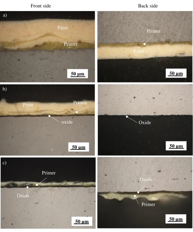
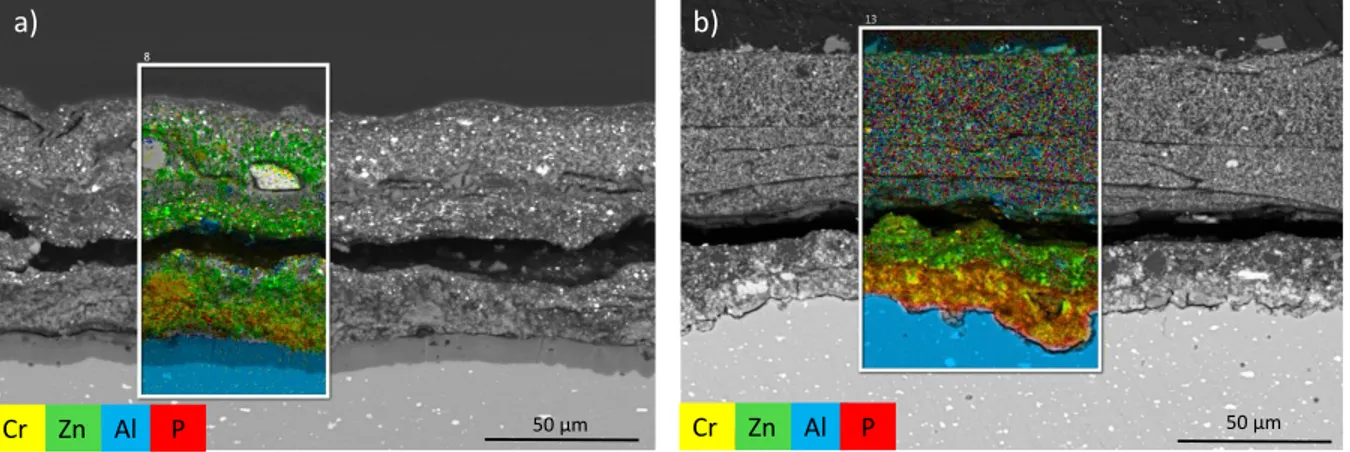
For each selected metallic part, the two surface sides were observed and analysed: the front side and the back side. The front side is defined here as the accessible or visible side when the part is still assembled on the aircraft, while the back side is in contact with another part when assembled, therefore non-accessible. Representative sections for all the coatings are reported in Figure 4 with possible identification. The nature of each layer was determined thanks to SEM-EDS analysis and XRD. On the bracket L9, the front side is too much altered by corrosion to detect any protective coating left. As seen in Figure 4, the protective coatings are quite different between the collected parts and between sometimes the front side and the back side for a same part. Nevertheless, some similarities exist. The transparent layer directly on the surface of the aluminium, detected on both sides of L8, L20 and on the backside of L9 and L15, is identified as an aluminium oxide with traces of sulphur. This oxidation layer is between 6 and 9 µm thick depending on the investigated part. On the plate L2 and on the rivets RL1 and RL2, no oxide layer is detected. Then, the light green layer on top of the oxide, seen on L9, L2, L8, L20, RL1, RL2 and on the backside of L15 is an organic layer containing chromium, zinc and phosphorous. XRD pattern collected on the light green layer (on L2 and L8 samples) allowed us to identify a zinc chromium oxide hydrate of formulae Zn2CrO5, H2O (PDF 11-0277) mixed with ZnO (PDF 89-0510) and TiO2 rutile (PDF 89-0554). On the profile L15, the front side appears very different from the back side and to the other parts (see Figure 4.e). On the front side indeed, no oxide is found (as opposed to the back side) and the primer is composed of two layers of different colours: a darker green layer at the surface of the aluminium and a light green layer on top as revealed from the EDS maps in Figure 5.
Figure 4. Optical microscope images (dark field mode) of protective coatings for both sides: a) L2, b) L8, c) L20, d): L9, e) L15, f) RL1, g) RL2. For L9, the front side was completely corroded and the coating no longer existed
Back side Front side Primer Paint 50 µm 50 µm Paint Primer oxide Oxide 50 µm 50 µm 50 µm Oxide Oxide Primer Paint Primer a) b) c) 50 µm Primer
(Figure 4. continued)
This double-layer, thicker and more resistant than the primer found on the other collected parts seems to have a similar nature but with a different composition. As shown in Table 2, it has a much higher phosphorus content (about 9 wt.% in the dark green) compared with 1 to 2
wt.% for the other primer L9 and it also contains some potassium (about 2.5 wt.%). XRD patterns on the dark green layer of L15 indicated clearly the presence of an aluminium phosphate AlPO4 (PDF 03-0446) and in the light green a potassium zinc chromium oxide hydrate of
d) 50 µm Oxide Primer 50 µm 50 µm Primer Oxide Paint Paint Primer 50 µm 50 µm Paint Primer Primer Paint e) f) Back side Front side g) Paint
formulae 4ZnCrO4, K2O, 3H2O (PDF 08-0202 XRD reference). This is in good agreement with the formulae reported in (Meynis de Paulin Novembre 1947). This chemical compound had proved to be an excellent inhibitor as well as resistant to humidity. Applied in a polybutyral vinyl solution mixed with an alcoholic solution containing phosphoric acid, a microcrystalline layer very adherent containing metallic phosphates was formed at the surface of the aluminium covered with a polybutyral vinyl (Raison 1979).
Eventually, on top of the primers, one or several paint layers (beige) containing carbon, oxygen, barium, titanium, zinc and sulphur were applied. The nature of some pigments was revealed by XRD: ZnO, TiO2 (rutile) were found as well as
BaSO4 and ZnS corresponding to the white pigment lithopone, a mixture of barium sulphate and zinc sulphide (O'Brien 1914).
C O Zn P Cr K Ti Traces L9 – Primer 59.5 ±1.0 23.5 ±0.6 8.6 ±0.9 1.9 ±0.3 1.8 ±0.2 0.2 ±0.1 2.0
0.6 Na, Mg, Al, Si, S
L15 – Primer 1 (Dark green) 30.0 ±4.6 32.3 ±2.3 10.1 ±2.5 9.2 ±2.5 7.4 ±2.6 2.5 ±0.7 0.3
±0.0 Na, Mg, Al, Si, Fe
L15 – Primer 2 (Light green) 53.1 ±3.2 23.8 ±1.3 3.2 ±0.5 0.1 ±0.0 2.5 ±0.5 1.0 ±0.3 11.6 ±1.0
Na, Mg, Al, Si, Fe
Table 2. Elemental composition (wt%) of the primers on L9 (back side) and L15 (front side), analysis by SEM-EDS: average on 3 areas.
Figure 1. Coating detected in L9 (back side) and L15 (front side) with SEM: backscattering image and EDS maps. Only Zn, P, Cr and Al are shown. In blue: Al-alloy, green: zinc, yellow:
chrome and red: phosphorus.
50 µm 50 µm
a) b)
Protective coating recommended by Breguet Company
The standard of Anglet (Breguet 1951-1959), exclusively reserved to aeroplanes 761 to 765, 960 and 1050 and gliders, details9 for each type of alloy and for each part, taking into account their role and location (inside or outside), the protective coating recommended (based on the AIR 7251 standard) and this, both for land and marine planes. The chemical nature of the protective coatings is however not detailed in the Company’s standards. Only acronyms and brand names are used: O.A.F.I.C. for anodic oxidation with chromic finishing, O.C.H.C. for chemical oxidation with chromium, and P50.I and P50.F for Impression and Finishing respectively of the P.50 set. To understand what stands behind these appellations, literature published in the 1950s was of great help.
For anodic oxidation first, workshops for aeronautical constructions in France and for Air Force maintenance possessed industrial installations for anodic oxidation using the sulfuric acid process (Rousset-Bert 1958). In particular, the installation in Louis Breguet factories of Anglet and Toulouse (France) allowed treating very large parts with tanks of 10 m long and 1 to 2 m deep. It is expected thus that the anodic oxidation applied by the company for the Breguet 765 was produced in such installation.
Chemical oxidation on the other hand was considered as a rapid process obtained at low temperature and without electrical current. It was thus quickly adopted in the aeronautical industry since 1945, in particular the Alodine 1200 process (Hess 1951) because of its high efficiency. The introduction of this new protection techniques called chemical oxidation based on chromium salts (O.C.H.C.) is
9 Fiche standard Br. 038, F.1. à 8, Novembre 1956– from Standard Forms, Anglet Factory (Breguet. 1951-1959).
mentioned in the standard of Breguet. It is also mentioned that the only chemical oxidation employed so far is the “Alodine 1200” provided by the C.F.P.I10.
At last, the full normalised P.50 painting set, specifically mentioned in the Breguet standard of 1956 should contain, according to the literature (Rousset-Bert 1958), several stages: degreasing, alkaline cleaning, a phosphate primer, a levelling and a nitro-synthetic finish. This painting set was chosen after a competition decided by the Service
technique de l’Aéronautique and thus
authorised in aeronautical applications. It replaced the P.42 set, selected from a competition which took place in 1942, which contained a primer based on alkyd resins but without chromates (Meynis de Paulin Novembre 1947). In the new painting set P.50, a phosphate primer was introduced.
Discussion: Laboratory analysis and archives study
Although the types of protective coatings that were employed by Breguet in his factories could be listed, and some information could be found in the literature on the characteristics and nature of these coatings, investigation performed on the collected parts allowed a more precise knowledge of the chemistry of the protective coatings. Confronting the identified protective coatings with the information collected on the Breguet standards was then attempted to highlight the true manufacturing and industrial use. This is summarised in Table 3 for each collected part and in parallel for recommended coatings as defined in the Breguet standard of Anglet from 1956 (Breguet 1951-1959) for marine and land planes. Thus, from Table 3, it can be distinguished similarities but also some
10 Compagnie Française des Produits Industriels, 177 quai du docteur Dervaux, Asnières (Seine) – from article C. Hess, RA 1951, n°174.
differences between real cases and recommended standards. For plates, L2 has only a primer protection, which is consistent with the case of inside plates for land aeroplanes, such as the Breguet 765. Conversely for plates L8 and L20 and for bracket L9 and profile L15, an anodic oxidation was applied prior the primer, which is the protection recommended only for marine aeroplanes. This is not coherent with the case of Breguet 765, a land aeroplane. At the moment, there is no logical explanation on why a protective coating specific to marine environment was applied to this aeroplane. Furthermore, plate L20 (outside skin – wing) which is an external part, should have received a chemical oxidation based on chromium salts (O.C.H.C.) corresponding to the Alodine 1200 product. However, in the materials analysis carried out on L20 and all other collected parts, no trace of Alodine 1200 was found. One explanation could be the following: the introduction of this new protection technique was mentioned in the standards of the Breguet Company, however, anodic oxidation was still used because it was considered by Breguet as the most efficient protection, even though more expensive.
The case of brackets in landing gear trap (L9) is not specifically mentioned in the standard. But the landing gear is a particularly severe environment as it is exposed to impacts of all sorts (in air and during take-off and landing), which could explain why an anodic oxidation was applied.
For rivets on land aeroplanes, anodic oxidation (O.A.F.I.C.) should have been applied. However, a note is given later in the document rectifying this recommendation, saying that rivets A-U3G are less sensitive to corrosion compared to A-U4G ones and they don’t react well to anodic oxidation. Breguet decided thus, to abandon this protection. Rivets, whether in A-U3G or in A-U4G were only covered, after assembling, by the primer and the finition coating (i.e. a painting) in good accordance with the descriptions in the Breguet standard of Anglet (Breguet 1951-1959).
Considering now the primers, as mentioned earlier, two types of primers were identified in the collected parts: one type, for most of the parts and another type, for the front side of part L15. In the first case, zinc chromate is the active pigment and it is mixed with titanium white (TiO2). A widespread technique was indeed to mix zinc chromate with other pigments (Meynis de Paulin Novembre 1947) to decrease the price and increase the coating power. Final content was usually 40 parts of zinc chromate for 100 parts of other pigments. On the other hand, the primer detected in L15 contains another pigment: a potassium zinc chromium oxide hydrate which produces, when mixed with a phosphorus acid contained in a polybutyral vinyl resin, a very adherent metallic phosphate layer at the surface of the aluminium. At this stage, it is difficult to determine which primer corresponds to the protection “P50.I. (impression)” depicted in the standard of Anglet and recommended (Table 3). However, the primer detected on the front side of L15 is maybe not representative and could correspond to a local repairing operation. One reason to think this is that the back side of L15 exhibits the same type of primer as the other parts with the presence of an oxide as well. An hypothesis can be formulated: on the accessible side, due to alteration during usage (such as corrosion for instance), L15 was probably de-oxidized in-situ, maybe by mechanical polishing, as the surface of this part seems rougher than for the rest of the other parts. Then the surface may have been treated with a new formulation of primer.
All these differences lead to the conclusion that for the Breguet Sahara 765, although built in 1958, the standard of Anglet from 1956 (Breguet 1951-1959) which concerns the protective coatings was not fully applied and adaptation was performed. Confronting materials analysis to archives is important as differences can exist between the real materials
used and the technical expected
construction is not linear. It is to be remembered that there were only 4 Breguet 765 built: this aeroplane is close to a prototype. Modifications may have been decided during manufacturing. Furthermore, repairing of some parts most probably occurred during the lifetime of the aeroplane and solutions for protection were changing in this period (new paint set P.50 for instance). All these factors are possible explanations for the differences found in primers.
Materials laboratory analysis Archives : Breguet standard N° Location
/ Alloy Side Nature (Thickness)
Location /
Alloy Land aircraft
Marine aircraft Plates Plates L2 Interior/ A-U4G1 Front & Back Primer (5-25 µm) + Paint (40-80 µm) Interior / U4G and A-U4G1 whether cladded or not Front (accessible) : P50.I O.A.F.I.C + P50.I Back (no access) : P50.I + F L8 Interior/ A-U4G Front Oxide (5-6 µm) + Primer (9-20 µm) + Paint Back Oxide L20 Exterior (wing) / A-U4G1 Front & Back Oxide (5-6 µm) + Primer (4-10µm) + Paint Exterior / U4G and A-U4G1 whether cladded or not O.C.H.C. + P50.I + F for plates ≤ 1 m/m O.A.F.I.C + P50.I + F Profiles Profiles L9 Exterior/ A-U4G1 Front Absent U4G and A-U4G1 P50.I before mounting O.A.F.I.C + P50.I + F Back Oxide (8-9 µm) +Primer + Paint L15 Interior/ A-U4G1 Front Phosphate (8-20 µm) + Primer (10-15 µm) + Paint Back Oxide (5µm) + Primer + Paint Rivets Rivets
RL1 A-U3G Primer + Paint A-U3G O.A. or
O.A.F.I.C O.A.F.I.C
Table 3. Protective coatings detected on the collected parts and information extracted from Anglet standard. For comparison, underline is used for oxides and corresponding industrial names (OAFIC and OCHC), italic for primers and corresponding industrial name (P50), bold
Conclusion
This work carried out on different parts collected on an aeroplane from the 1950s revealed a number of information on aluminium alloys and protective coatings employed in the French aeronautical industry. Different alloys, namely A-U4G, A-U4G1 and A-U3G, were identified depending on their role in the aeroplane, in coherence with the Breguet standard: A-U4G1, with a higher concentration
of magnesium and high mechanical
characteristics, was used for structural parts, whereas A-U4G for cladding parts. Rivets were made out of A-U3G and A-U4G depending on their diameter. The microstructure of the different studied parts revealed some differences mainly due to the manufacturing process (rolling or extrusion) and/or post-manufacturing treatments. In terms of protective coatings, we could highlight the use of anodization and primers and identify the nature of the anticorrosive pigments within the primers by cross-checking analysis from different techniques: optical microscopy, SEM-EDS and XRD. Raman and Infra-Red spectroscopies, Gas-Chromatography-Mass Spectrometry are complementary techniques which would help identifying the organic binders.
As regards to the usefulness of all the information retrieved, several points can be made. Firstly, even if historical research is a basic fundamental approach, archives are sometimes difficult to localise and not complete. On the other hand, changes for particular aircraft could be decided by the constructors, as it was demonstrated here for the alloys and for the protection coatings. Therefore, archives alone are not sufficient for full reconstitution of reality on a specific aircraft. Furthermore, in technical archives, materials are most of the time mentioned under commercial names that sometimes no longer exist, which make the identifying task difficult: for instance, the exact nature of the protective coating P.50 employed by Breguet in 1958 yet remains to be found. The investigation of
ancient aeroplane materials by direct characterisation helps, thus, correlating the historical archives with the effectively applied industrial process, for an improvement of the history of techniques and science. It also helps preserving and transmitting aeronautic testimony. In fact, documenting thoroughly materials should be considered whenever possible as aircraft conserved outdoor are threatened of destruction: corrosion attacks push people in charge of the conservation to replace parts.
Secondly, there is no doubt that the information on aeronautical materials will help improving conservation practices. For defining the conservation state of aircraft metallic elements, the full characterisation of both the metallic bulk material (especially its microstructure at different scales) and the applied protection remains fundamental, as often for cultural metallic artefacts. Understanding alterations (in this case corrosion) will consist in looking for influencing factors: nature of the alloy, alteration of the coating, and for industrial cultural heritage, such here for aeronautics, it is also mandatory to take into consideration their location and role on the aircraft as well as possible environmental conditions, during and after usage, to establish an appropriate diagnosis of the conservation state. This particular point will constitute the heart of our future work.
Eventually, this study can help the understanding of the materials involved in other aircraft’s construction in the same period. A mid-term perspective will be to implement a database specific for these cultural heritage filing all these information. This would allow complete and crossed researches on aluminium aeronautic alloys from an historical and materials point of view, also providing an aid to curators willing to confront their own observations to references.
Acknowledgements
The authors would like to thank the volunteers of the association Les Ailes Anciennes Toulouse, especially the team ‘Breguet-2 ponts’: Patrick Goutoule, Michel Frostin, Laurent Malric, Albert-Franz Van Dew Bussche, Daniel Hartmann, Yves Martin as well as André Sunez, André Suzon, Jacques Leborgne for their availability, their help in sampling, archives research and histories around the aircraft.
This study has been partially supported through the grant NanoX n° ANR-17-EURE-0009 in the framework of the « Programme des Investissements d’Avenir”.
References
Adams, C. and D. Hallam. 1991. "Finishes on Aluminium - a Conservation Perspective". Paper presented at the Symposium '91: Saving the Twentieth Century, in Ottawa, Canada.
AIR 3350/C. 1957. "Tableaux des alliages d'aluminium et des alliages de magnésium", 5: Ministère de la Défense Nationale et des Forces Armées, Secrétariat d'Etat aux Forces Armées (AIR), Direction Technique et Industrielle, edition n°4, 15th of june 1957. Archive. 1957. Letter from the "Directeur Général of
Breguet" to the "Directeur du Service des Marchés et de la Production Aéronautique", lettre n°29308, 27th of August 1957. MINDEF- Service Historique de la Défense, Châtellerault, AA 633 094 464.
Bailly, J. 1936. "Construction en Vedal pour hydraviation". In Revue de l'Aluminium et de ses
Applications n° 78, 55-60.
Breguet. 1946-1954. Standard Forms, Vélizy Factory.
Archives Data, Ailes Anciennes Toulouse.
Breguet. 1951-1959. Standard Forms, Anglet factory. In
MINDEF - Service Historique de la Défense, Châtellerault, AA 416 2C5 199.
Breguet. 1956. Technical Clauses for Breguet 765: Service Technique de l'Aéronautique - Section Avions, Centre de Documentation du Musée de l'Air et de l'Espace du Bourget.
Breguet. n.d. Descriptive Record for the Aircraft Operation, Breguet 765, Sets Part. Direction Centrale du Matériel de l'Armée de l'Air: Archives Data, Ailes
Anciennes Toulouse.
Chadeau, E. 1987. De Blériot à Dassault. L'industrie
aéronautique en France (1900 -1950). Fayard, Paris,
552 p.
Chevigny, R. 1954. "L'aluminium et ses alliages". Revue
de l'Aluminium, no 211: 175.
Cochard, A. 2016. "Microstructure et propriétés mécaniques des alliages de type Duralumin du Breguet 765 n°504 64-ph, PhD Thesis, Doctorat of the
Université de Toulouse.
Cochard, A., J. Douin, B. Warot-Fonrose, J. Huez, L. Robbiola, J.-M. Olivier and P. Sciau. 2013. "Benefits of the Complementary Use of Archaeometry Investigations and Historical Research in the Study of Ancient Airplanes: The Breguet Sahara's Rivets". Paper presented at the MRS Fall Meeting, in Boston. Cochard, A., K. Zhu, S. Joulie, J. Douin, J. Huez, L.
Robbiola, P. Sciau and M. Brunet, 2017. "Natural Aging on Al-Cu-Mg Structural Hardening Alloys – Investigation of Two Historical Duralumins for Aeronautics". Materials Science and Engineering: A 690: 259-269.
Dix, E.H.J. August 1927. "Alclad": A New Corrosion Resistant Aluminum Product. In Technical Notes -
National advisory comittee for aeronautics: Research
Bureau, Aluminum Company of America.
Fontaine, C. 1909. "Un grand français, Blériot, franchit la Manche en aéroplane". In Le Matin. consulted on https://www.retronews.fr/
Gayle, F.W. and M. Goodway. 1994. "Precipitation Hardening in the First Aerospace Aluminum Alloy: The Wright Flyer Crankcase". Science 266, no 5187: 1015.
Guilminot, E. and Y. Tissier. 2015. "Etude des alliages aluminium pour la mise au point des traitements de conservation des avions", Journal of the History of
Aluminium 54: 82-93.
Hall, E.O. 1951. "The Deformation and Ageing of Mild Steel: Discussion of Results". Proceedings of the
Physical Society. Section B 64, no 9: 747.
Hardouin Duparc, O. 2005. "Alfred Wilm et les débuts du Duralumin". In Cahiers d'histoire de l'Aluminium, 63-77. Paris: Institut pour l'Histoire de l'Aluminium. Hess, C. 1951. "Le procédé Alodine, protection
galvanique de l'aluminium". In Revue de l'Aluminium, no. 174: 44-50.
Hornbogen, E. 2001. "Hundred Years of Precipitation Hardening". Journal of Light Metals 1, no 2: 127-132. Hughes, A.E., A.M. Glenn, N. Wilson, A. Moffatt, A.J. Morton and R.G. Buchheit. 2013. "A Consistent Description of Intermetallic Particle Composition: An Analysis of Ten Batches of AA2024-T3". Surface and
Interface Analysis 45, no 10: 1558-1563.
Hérenguel, J. and P. Lelong. 1958. "Un mécanisme métallurgique particulier à l'extrusion : L’hypercorroyage". Rev. Met. Paris 55, no 11: 1057-1064.
Lebouteux, H. 1956. "La symbolisation de l'aluminium et de ses alliages en France et dans quelques pays étrangers". In Encyclopédie du travail de l'aluminium,
Meynis De Paulin, J.-J. Novembre 1947. "La peinture de l'aluminium - Part 2". In Revue de l'Aluminium n°138, 325-331.
Meynis De Paulin, J.-J. Octobre 1947. "La peinture de l'aluminium - Part 1". In Revue de l'Aluminium n°137, 309-15.
Mikesh, R.C. 2009. Restoring Museum Aircraft. Atglen, PA, USA: Schiffer Publishing Ltd.
Mondolfo, L.F. 1976. Aluminum Alloys, Structure and
Properties. London-Boston: Butterworths.
O'Brien, W.J. 1914. "A Study of Lithopone". The Journal
of Physical Chemistry 19, no 2: 113-144.
Olivier, J.-M. 2014. Histoire de l'armée de l'air et des
forces aériennes françaises du XVIIIème siècle à nos jours. Editions Privat, Evreux, 547 p.
Orville Wright and Wilbur Wright. September 1908, n°5. "The Wright Brother's Aeroplane". In The Century
Magazine.
Pattillo, D.M. 1998. Pushing the Envelope : The
American Aircraft Industry. Ann Arbor: University of
Michigan Press.
Penel, P. 1950. "Fiche H - Octobre 1950: Le traitement thermique des alliages légers. Première partie: trempe et revenu". In Encyclopédie du travail de l'aluminium,
extrait de la Revue de l'Aluminium n°170, 173 et 175, Paris.
Polmear, I.J. 2005a. 2 - "Physical Metallurgy of Aluminium Alloys". In Light alloys (fourth edition), ed. Polmear, Ij, 29-96. Oxford: Butterworth-Heinemann.
Polmear, I.J. 2005b. 3 - "Wrought Aluminium Alloys". In
Light alloys (fourth edition), ed. Polmear, Ij, 97-204.
Oxford: Butterworth-Heinemann.
Pubellier, M. 1931. "La protection des alliages légers contre la corrosion". In Revue de l'Aluminium, no 46: 1596-1600.
Raison, M. 1979. "Revêtements des métaux par peinture".
Techniques de l'Ingénieur M 1 505.
Rocca, E., F. Mirambet and C. Tilatti. 2010. "Long Term Corrosion of Aluminium Materials of Heritage: Analysis and Diagnosis of Aeronautic Collection".
Corrosion Engineering Science and Technology 45,
no 5: 345-349.
Rousset-Bert, P. 1958. "La protection des structures en métal léger dans la construction aéronautique".
Corrosion et Anticorrosion 6, no 9: 74-89.
Silcock, J.M., T.J. Heal and H.K. Hardy. 1954. "Structural Ageing Characteristics of Binary Aluminium-Copper Alloys". Journal of the Institute of Metals: 82: 239-248.
Spruance, F.P. 1945. "Composition for and Method of Coating Aluminum". In US Patent 2,438,877. Starink, M.J., N. Gao and J.L. Yan. 2004. "The Origins of
Room Temperature Hardening of Al–Cu–Mg Alloys".
Materials Science and Engineering: A 387-389:
222-226.
Starke Jr, E.A. and J.T. Staley. 1996. "Application of Modern Aluminum Alloys to Aircraft". Progress in
Aerospace Sciences 32, no 2–3: 131-172.
TICCIH. 2011. "Principles for the Conservation of Industrial Heritage Sites, Structures, Areas and Landscapes". In Dublin principles - Adopted by the
17th ICOMOS General Assembly on 28 November 2011. http://ticcih.org/about/about-ticcih/dublin-principles/.
Tournaire, M. and M. Renouard. 1956. "Alliages pour rivets de la famille du Duralumin". Revue de