HAL Id: tel-03126748
https://pastel.archives-ouvertes.fr/tel-03126748
Submitted on 1 Feb 2021HAL is a multi-disciplinary open access
archive for the deposit and dissemination of sci-entific research documents, whether they are pub-lished or not. The documents may come from teaching and research institutions in France or abroad, or from public or private research centers.
L’archive ouverte pluridisciplinaire HAL, est destinée au dépôt et à la diffusion de documents scientifiques de niveau recherche, publiés ou non, émanant des établissements d’enseignement et de recherche français ou étrangers, des laboratoires publics ou privés.
Application to autonomous vehicles
Imane Mahtout
To cite this version:
Imane Mahtout. Youla-Kucera based multi-objective controllers : Application to autonomous vehi-cles. Automatic Control Engineering. Université Paris sciences et lettres, 2020. English. �NNT : 2020UPSLM044�. �tel-03126748�
definition example Rem
Préparée à MINES ParisTech
Youla-Kucera based multi-objective controllers:
Application to autonomous vehicles
Contrôleurs multi-objectifs basés sur Youla-Kucera:
Application aux véhicules autonomes
Soutenue par
Imane MAHTOUT
Le 21 décembre 2020
École doctorale no621
Ingénierie des Systèmes,
Matériaux, Mécanique,
En-ergétique
SpécialitéINFORMATIQUE
TEMPS
REEL,
ROBOTIQUE
ET
AUTOMATIQUE
Composition du jury : Philippe MARTINETINRIA Sophia Antipolis Président/Rapporteur
Concepción MONJE
Universidad Carlos III Rapporteur
Lydie NOUVELIERE
Univ d’Evry Examinateur
Joshué PÉREZ RASTELLI
Tecnalia Examinateur
Vicente MILANES
Renault Examinateur
Fawzi NASHASHIBI
To Lila, this accomplishment is also yours. Thank you for all the courage and strength you gave me. To Abderrezak, I hope that will make you proud. Thank you for the perseverance that you taught me.
Acknowledgments
This thesis is the result of three years of hard and challenging work, but also passion and completion. Many people accompanied me to accomplish this work. I hope these few lines would express my gratitude and acknowl-edgment to to those how made it possible.
First of all, I thank Almighty God for giving me the courage, strength and patience to complete this modest work.
Great gratitude to my parents for their encouragement, aid and educa-tion. Thanks to Nawel for all the coffees, Nesrine for the awakenings, and Adam for the good evening atmosphere.
I would like to thank my supervisors Vicente and Fawzi for giving me the chance to integrate their teams and benefit from their research expertise, I learned a lot from their knowledge, within the multiple technical discussions. Without their supervision, patience and kindness this work could not be achieved .
For all my friends and colleagues, the people who shared this work, a big and sincere acknowledgment for all. Especially Riadh, Madjda, Asma, Lucille, Nievsabel, Hussam, Kathia, Raoul, Luis, Jean Marc for their help and all rewarding discussions.
A special and great gratitude to my colleagues and friends David and Francisco, for having welcomed me into the ”dream team” and having shared their knowledge and experience, without their efforts and their help my work would not have been successful. I have learned a lot from them during these three years.
Contents
1 Introduction 3 1.1 Motivation . . . 3 1.2 Objectives . . . 4 1.3 Manuscript organization . . . 5 1.4 Contribution . . . 6 1.5 Publication . . . 7 1.5.1 Journals . . . 7 1.5.2 Conferences . . . 8 1.5.3 Patents . . . 82 Youla-Kucera state-of-the-art review and applications 11 2.1 Origins of YK parametrization . . . 12
2.1.1 Coprime factorization . . . 13
2.1.2 Q-parametrization . . . 14
2.1.3 S-parametrization . . . 14
2.1.4 (Q,S)-parametrization . . . 14
2.2 Q-based controller reconfiguration . . . 15
2.2.1 Control implementation . . . 16
2.2.2 Applications . . . 18
2.3 Q-based noise rejection and vibration control . . . 19
2.3.1 Control implementation . . . 19
2.3.2 Applications . . . 22
2.4 S-based closed-loop identification . . . 23
2.4.1 Identification scheme . . . 24
2.4.2 Applications . . . 25
2.5 (Q,S)-based adaptive control . . . 26
2.5.1 Control implementation . . . 26
2.5.2 Applications . . . 28
2.6 (Q,S)-based fault tolerant control . . . 28
2.6.1 Control implementation . . . 29
2.6.2 Applications . . . 30
2.7 (Q,S)-P&P and Multi Model Adaptive Control . . . 31
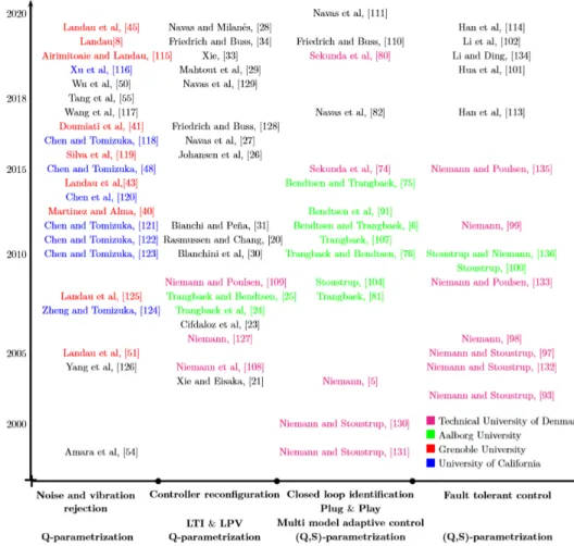
2.8 YK and Dual-YK Time Evolution . . . 32 V
2.9 Discussion . . . 34
3 Youla-Kucera parametrization: Theory and principles 39 3.1 Introduction . . . 39
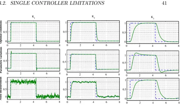
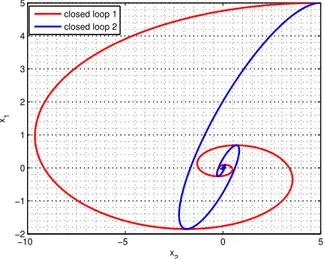
3.2 Single controller limitations . . . 40
3.2.1 Single multi-criteria controller . . . 42
3.2.2 Linear controller switching . . . 43
3.3 YK: definition and stability . . . 46
3.3.1 Doubly Coprime Factorization . . . 47
3.3.2 The class of all stabilizing controllers . . . 49
3.3.3 Controller transition . . . 51
3.3.4 Youla-Kucera controller stability analysis . . . 53
3.4 Numerical example . . . 61
3.5 Conclusion . . . 65
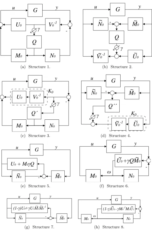
4 Transient behavior analysis for YK control structures 67 4.1 YK control structure implementations . . . 68
4.2 Transient behavior . . . 70
4.2.1 γ placement . . . . 70
4.2.2 Initial and final controllers dynamics . . . 72
4.2.3 Switching frequency . . . 74
4.3 Conclusion . . . 76
5 Lateral Control 79 5.1 Experimental platform description . . . 80
5.2 Problem description . . . 82
5.3 Lateral control review . . . 84
5.4 Motivation on using Youla Kucera . . . 87
5.5 Control design . . . 89 5.5.1 Vehicle model . . . 90 5.5.2 Steering actuator . . . 93 5.5.3 Lateral controller . . . 97 5.5.4 Stability Analysis . . . 101 5.6 Simulation results . . . 103 5.7 Experimental results . . . 105 5.8 Conclusion . . . 106 6 Longitudinal Control 109 6.1 Problem description . . . 110
6.2 Longitudinal control review . . . 113
6.3 Motivation on using Youla Kucera . . . 116
6.4 Control design . . . 117
6.4.1 Performant controller criteria . . . 117
CONTENTS VII
6.4.3 Nominal controllers design . . . 118
6.4.4 Parametrized controller K(Q) . . . 120
6.5 H∞ controller . . . 122
6.6 Comparison results . . . 124
6.6.1 Frequency domain comparison . . . 124
6.6.2 Temporal domain comparison . . . 126
6.7 Experimental results . . . 129
6.8 Conclusion . . . 133
7 Discussion 135 7.1 Conclusion . . . 135
1
Chapitre 1
Introduction
Below is a French summary of chapter 1.
Le véhicule autonome peut percevoir et comprendre son environnement grâce à des systèmes de prise de décision basés sur l’intelligence artificielle (IA). Ces systèmes sont de plus en plus populaires en raison des avan-tages qu’ils peuvent apporter pour améliorer les performances des véhicules. Cependant, ces systèmes sont basés sur un apprentissage de l’environnement, exigeant une évolution continue également du point de vue du contrôle du véhicule. Ainsi, la reconfiguration automatique des contrôleurs peut être une solution pour garantir des hautes performances de conduite, l’objectif étant que le système de contrôle s’assure que la réponse du véhicule soit adaptée aux besoins de la partie décisionnelle dans chaque situation de manière sûre, fiable et robuste.
Le problème principal se pose lorsque la transition entre de tels algo-rithmes de contrôle se produit, conduisant à des instabilités indésirables. Cette thèse se concentre sur une étude plus approfondie des environnements dynamiques complexes qui conduira à des structures de contrôle avancées, permettant des transitions multi-contrôleurs tout en prenant en compte les dysfonctionnements de capteurs ou les circonstances de la circulation.
Cette thèse est développée dans le cadre du doctorat CIFRE. Les travaux de recherche ont été réalisés entre l’équipe Robotique et Systèmes de Trans-port Intelligents (RITS) de l’Institut National de Recherche en Informatique et en Automatique (INRIA) , en collaboration avec le constructeur auto-mobile Renault (Technocentre). La motivation de la thèse, les objectifs, l’organisation du manuscrit et ses principales contributions sont présentés ce chapitre.
Chapter 1
Introduction
Autonomous vehicle can perceive and understand their environment thanks to Artificial-Intelligence (AI) based decision-making systems. Such systems are getting more and more popular because of the benefits they can bring to improve vehicle performance. However, these systems are based on a con-stant learning of the environment, demanding a continuous evolution also from the system control point of view. Thus automated controller reconfig-uration can be a solution for guaranteeing the desired vehicle performance. The aim is that the control system ensures that the vehicle response is suitable for the needs of the decision-making part in each traffic situation, being able to manage them in a safe, reliable and robust manner. The main problem arises when the transition between such control algorithms occurs, leading to undesirable instability responses. This PhD is focused on further investigate complex dynamic environment that will lead to advanced control structures, enabling multi-controller transitions while taking into account sensors failures or traffic circumstances.
This thesis is developed within the framework of the PhD CIFRE (from french: Convention Industrielle de Formation par la Recherche), research work has been accomplished between the Robotics and Intelligent Trans-portation Systems team (RITS) at the French national institute INRIA for research in computer science and automatics (from french: Institut National de Recherche en Informatique et en Automatique), in collaboration with Re-nault research centre (from french: Technocentre). The motivation of the thesis, the objectives, manuscript organization and its main contributions are presented below.
1.1 Motivation
Interest in intelligent vehicles research has been growing in the last two decades, with the aim of improving transportation security and comfort. Autonomous vehicle refers to technology that has the capability to drive
a vehicle without active physical control or monitoring by a human op-erator [1]. According to the Society of Automotive Engineers (SAE), five automation levels are defined: Levels 0–2 are those where the human driver needs to monitor the driving environment, and levels 3–5 are those where an automated driving system monitors the driving environment. The term ”Autonomous driving” should refer only to the case where all the dynamic driving tasks, at all driving environment perception, can be performed by the vehicle’s automated system [2]. This corresponds to SAE level 4 when it happens in a pre-defined Operational Design Domain (ODD) or SAE level 5 if the vehicle is able to deal with all circumstance no matter the ODD.
Driving requires a variety of functions, including localization, perception, planning and control [3]. Information acquisition is specific to localization and perception functions. Communications with other vehicles vehicle-to-vehicle (V2V), or with the infrastructure vehicle-to-vehicle-to-infrastructure (V2I), can also be additional source of information to help the vehicle when negotiating intersection maneuvers [1]. However, the accuracy of these information may be degraded because of the on-board sensors’ limitations, or the complexity of the algorithm processing the perceived data. Furthermore, the driving situations change depending on the road layout and potential interactions with other traffic agents. The aforementioned factors can lead to inappropri-ate vehicle motion. This work focuses on developing control structures and algorithms, ensuring the desired system performance regardless to the oper-ating conditions, able to drastically change vehicle dynamics while keeping its stability.
The concept of controller reconfiguration by interpolating multiple con-trollers is tackled in the literature using different techniques. In this thesis, Youla-Kucera (YK) parametrization is explored as a controller reconfigura-tion framework, guaranteeing stable transireconfigura-tion under arbitrary switching.
1.2
Objectives
The main objective of this PhD work is to further explore complex scenarios where autonomous vehicles can drive. Situations where different expecta-tions can interact as keeping the vehicle in the lane but at the same time having a potential obstacle to avoid.
• Review of the state-of-the-art on YK and dual YK parametrizations field, and its use on different control applications.
• Understand different YK structures in the field of controller reconfigu-ration and switching, and analyze their respective responses according to the different benefits and drawbacks.
• Study the transient behavior when doing controller reconfiguration using YK parametrization.
1.3. MANUSCRIPT ORGANIZATION 5 • Application to lateral control of autonomous vehicles. Focusing on handling different driving situations involving lateral motion with a high performance level and keeping a comfortable feeling in the vehicle. • Application to longitudinal control of autonomous vehicle. When deal-ing with the problem of inaccurate measurement caused by the limita-tions of the perception system. Longitudinal controller should be able to provide the best possible response in all circumstances, while main-taining longitudinal control stability, string stability and measurement noise rejection.
• Automatic control reconfiguration to achieve optimal performance in both lateral and longitudinal control is the principal challenge of this work. The final goal is to find the optimal control law to achieve the best performance possible when structural changes have been intro-duced.
• Focus is in obtaining control algorithms running in a real experimental research platform validating the efficiency of the proposed solutions in a real traffic conditions.
1.3 Manuscript organization
This PhD thesis has been organized in seven chapters. A brief overview of each of the remaining chapters is given below:
Chapter 2, Youla-Kucera state-of-the-art review and applications:
This chapter presents a review of the YK and dual YK parametrizations re-lated to different control fields. Especially, controller reconfiguration, iden-tification, Plug&Play control, disturbance rejection, adaptive control, and fault tolerant control. Important groups worldwide are reviewed, classifying the recent work according to the use of YK or dual YK parametrizations or both, providing the latest advances with main successful applications developed in the last two decades in different control fields.
Chapter 3, Youla-Kucera parametrization: Theory and principles:
The basis on building a multi-objective controller based on YK parametriza-tion are presented in this chapter. It also introduces the mathematical framework of doubly coprime factors. A deep stability analysis of YK based controller is provided using stability notions of system with impulse effects. Numerical examples are given, showing the steps to build a YK based con-troller, and proving how it stabilizes a transition between two controllers where direct linear change results unstable, having a state dependent switch-ing signal.
Chapter 4, Transient behavior analysis for YK control structures:
This chapter studies the transient behavior of the different YK implemen-tations according to different design parameter: switching signal placement,
closed-loop bandwidth capabilities of each controller; and switching signal frequency. The evaluation is carried out from the time-to-convergence point of view using a numerical example.
Chapter 5, Lateral Control: YK parametrization is explored to deal with
lateral control problem of automated vehicles. The controller reconfiguration is based on a decision taking into account the lateral error corresponding to the driving situation, which allow the steering system to perform different maneuvers, while maintaining stability, control performance and passengers comfort.
Chapter 6, Longitudinal Control: This chapter presents a YK based
ACC system for automated vehicles. The proposed control structure ex-tends the classical ACC system capabilities by providing the best possible response when facing variable noise measurement, meaning that the con-troller is able to change in real time according to the noise level in the perception system, while maintaining longitudinal control stability, string stability and measurement noise rejection.
Chapter 7, Discussion: It includes conclusions and most important
re-marks, with respect to the problems addressed in the present thesis. As well as research perspective that could be derived from the results of this PhD work.
1.4
Contribution
The main contributions in the present dissertation are as follows:
1. YK parametrization allows stable controller reconfiguration within the set of the stabilizing controller for a given plant. Eight different im-plementations are derived in the literature with different benefits and drawbacks. A first comparative study concluded that one structure presents the best transient behavior without oscillations. However, the transient behavior could be enhanced from time to convergence point of view. In this thesis, the eight structures are compared with respect to three design parameters: 1) The position of the switching signal γ with respect to the YK parameter Q; 2) The nominal con-troller dynamic; 3) The frequency of the switching signal γ. This study results on implementation guidelines for each YK structure, in order to enhance the control performance during the transient behavior. 2. YK based lateral controller for autonomous vehicle is proposed to deal
with the trade-off between precision in trajectory tracking and comfort when the driving situation changes in lateral motion. The proposed control strategy switches gradually between different controllers based on a look-ahead distance designed separately for each driving situa-tion (i.e. lane change, lane tracking). It ensures smooth and stable
1.5. PUBLICATION 7 transitions between controllers and provides a smooth vehicle response regardless of the driving situation. The controller reconfiguration is based on a decision taking into account the lateral error corresponding to the driving situation.
3. A novel multi-objective YK based controller is designed to solve the trade-off between robustness and performance when noise measure-ment appears in Adaptive Cruise Control (ACC) systems. The YK based controller adapt the longitudinal vehicle motion to the percep-tion system status. This solupercep-tion extends the ACC system capabilities by providing the best possible response in all circumstances, meaning that the controller is able to change in real time according to the noise level in the perception system, while maintaining longitudinal control stability, string stability and measurement noise rejection.
4. YK based multi-objective controllers are proposed in this thesis, en-hancing the performance of both longitudinal and lateral motion of autonomous vehicles. Proving the efficiency of the YK parameter-ization as a control framework when dealing with conflicting control objectives. For an initial validation the designed controllers was tested in simulation. Also experimental results demonstrate real implemen-tation of stable controller reconfiguration using an electric automated Renault ZOE.
1.5 Publication
The scientific contributions derived as a result of the developed research work are listed below:
1.5.1 Journals
Title: Advances in Youla-Kucera parametrization: A Review Authors: I. Mahtout, F. Navas, V. Milanés, F. Nashashibi Journal: Annual Reviews in Control
Status: Published by Elsevier. Volume: 49, 2020. Pages: 81-94.
Title: On the Passenger Acceptance of Driverless Shuttles Authors: V. Milanés, F. Navas, D. Gonzalez, I. Mahtout. Journal IEEE Intelligent Transportation Systems Magazine Status: Published by IEEE. Date: April 2020
Title: Youla-Kucera based Multi-objective Car Following Controller Authors: I. Mahtout, F. Navas, D. Gonzalez, V. Milanés, F. Nashashibi Journal Control Engineering Practice
Status: 1st revision.
1.5.2 Conferences
Title: Youla-Kucera based lateral controller for autonomous vehicle Authors: I. Mahtout, F. Navas, D. Gonzalez, V. Milanés, F. Nashashibi Conference: 2018 21st International IEEE Conference on Intelligent
Trans-portation Systems (ITSC)
Place: Maui, Hawaii, USA Date: November 4-7
Title: Youla-Kucera control structures for switching Authors: F. Navas, I. Mahtout, V. Milanés, F. Nashashibi
Conference: 2018 IEEE Conference on Control Technology and
Applica-tions (CCTA)
Place: Copenhagen, Denmark Date: August 21-24, 2018
Title: A first approach for a passenger-centered behavior on driverless
ve-hicles
Authors: D. Gonzalez, F. Navas, I. Mahtout, V. Milanés
Conference: 2020 28th Mediterranean Conference on Control and
Automa-tion (MED)
Place: Saint-Raphael, FRANCE Date: September 16-18, 2020
1.5.3 Patents
Because of the CIFRE opportunity at Renault, I had the opportunity to col-laborate on several projects, leading to different patents submissions. Below includes a list of my cooperation within my working time at Renault.
Title: Safety positioning device for autonomous vehicle with apparatus for
taking the vehicle to a safe state
Authors: V. Milanés, I. Mahtout, D. Gonzalez, F. Navas
1.5. PUBLICATION 9
Title: A vehicle dynamic model corrector with side slip estimation for
adding safety capabilities in autonomous vehicle
Authors: I. Mahtout, V. Milanés, D. Gonzalez, F. Navas
Status: Accepted in RENAULT SAS Date: September 23, 2019
Title: Safety starting vehicle alignment apparatus for automated vehicle
applications in autonomous mode engagement, docking/undocking and tele-operation maneuvers
Authors: V. Milanés, I. Mahtout, D. Gonzalez, F. Navas Status: Accepted in RENAULT SAS Date: August 28, 2019
Title: Safety collision-free and string stable automated car following device Authors: V. Milanés,I. Mahtout, D. Gonzalez, F. Navas
Status: Accepted in RENAULT SAS Date: August 29, 2019
Title: Apparatus and method for automatically model brand
multi-vehicle steering systems for auto-tuned autonomous lateral guidance device
Authors: V. Milanés, I. Mahtout, D. Gonzalez, F. Navas Status: Accepted in RENAULT SAS Date: April 04, 2020
Title: Perception-adapted controller device for autonomous vehicles Authors: I. Mahtout, V. Milanés, D. Gonzalez, F. Navas
Chapitre 2
Etat de l’art de la parametrisation
de Youla-Kucera et ses applications.
Below is a French summary of chapter 2.
Ce chapitre correspond à un état de l’art réalisé du point de vue des applications utilisant la parametrisation de Youla-Kucera et son duel. Ces paramétrisations ont été utilisées dans différents systèmes de contrôle pra-tiques, couvrant la reconfiguration des contrôleurs, l’identification, le con-trôle Plug&Play (P&P), le rejet des perturbations, le concon-trôle adaptatif et la commande tolérantes aux défauts.
L’origine de la paramétrisation de YK se situe dans les années 70, Youla [4, 5] et Kucera [6] ont développé la base scientifique. Ils ont proposé une paramétrisation qui fournit tous les régulateurs stabilisant un systeme linéaire dans une boucle de régulation à retour de sortie. Tous les régula-teurs de stabilisant sont paramétrés en utilisant une fonction de transfert appelée paramètre de YK Q, conduisant à une forme de contrôlleurs K(Q). Le paramètre Q(s) garantit la stabilité de la structure de contrôle resultante. De même, sa théorie duelle (également connue sous le nom de paramétri-sation duel de YK) fournit tous les systèmes linéaires stabilisées par un contrôleur donné. La classe de tous les systèmes stabilisés par un contrôleur dépend de la fonction de transfert appelée paramètre duel de YK S, donc
G(S). Ce paramètre peut représenter n’importe quelle variation du système.
Ainsi, cette façon utile de paramétrer soit les systèmes, soit les contrôleurs, soit les deux, est utilisée pour résoudre de nombreux problèmes de contrôle. Ce chapitre rassemble les travaux récents et les classifie selon l’utilisation de la paramétrisation YK ou de la duelle paramétrisation de YK ou des deux, en fournissant les dernières avancées avec les principales applications réussies développées au cours des deux dernières décennies dans différents domaines de contrôle. Une discussion finale donne un aperçu des tendances futures dans ce domaine.
Chapter 2
Youla-Kucera state-of-the-art
review and applications
This chapter corresponds to a state-of-the-art review that was carried out from the applications of YK and dual YK parametrizations point of view. These parametrizations have been used in different practical control sys-tems, covering controller reconfiguration, identification, Plug&Play (P&P) control, disturbance rejection, adaptive control, and fault tolerant control.
YK parametrization was formulated in the late 70s for obtaining the set of controllers stabilizing a linear plant. This fundamental result of control theory has been used to develop theoretical tools solving many practical control problems. This chapter collects the recent work and classifies them according to the use of YK parametrization or dual YK parametrization or both, providing the latest advances with main successful applications developed in the last two decades in different control fields. A final discussion gives some insights on the future trends in the field.
The rest of the chapter is organized as follows: Section 2.1 presents fundamentals and mathematical basis of YK and dual YK parametriza-tions. Section 2.2 presents the use of the YK parameter Q as a technique of controller reconfiguration for both Linear Time-Invariant (LTI) and Linear Parameter-Variant (LPV) systems. Disturbance and noise rejection con-trol structure based on the YK parameter Q is explained in section 2.3. In section 2.4, the use of dual YK parameter in closed-loop identification is presented. The combination of both YK parameter and dual YK parameter in adaptive control field is detailed in section 2.5. The fault tolerant control scheme based on YK framework is detailed in section 2.6. In section 2.7, the use of YK parametrizations in Plug & Play control and Multi Model Adaptive Control is briefly reviewed. Finally, some challenging issues about the use of YK parametrization are discussed in the last section.
2.1
Origins of YK parametrization
The origin of the YK parameterization is in the 70s, Youla [4,5] and Kucera [6] developed the scientific basis. They proposed a parameterization that provides all linear stabilizing controllers for a given LTI plant in a feedback control loop (see Fig. 2.1). All stabilizing controllers are parametrized based on the transfer function called YK parameter Q, leading to a control form
K(Q). The parameter Q(s) is the one guaranteeing the stability. Similarly,
its dual theory (also known as the dual YK parametrization) provides all the linear plants stabilized by a given controller. The class of all the plants stabilized by a controller depends on the transfer function called dual YK parameter S, so G(S). This parameter could represent any plant variations. Hence, this useful way of parametrizing either plants, controllers or both is employed to solve many control issues.
Figure 2.1: Feedback control loop block diagram.
According to the control objectives, three main configurations can be targeted:
• Controller parametrization allows stable controller reconfiguration when some change occurs. It is also widely used in disturbance and noise rejection control. A number of successful applications can be found in the last two decades, being the most used approach in different control fields [7].
• Plant parametrization is employed to solve the problem of closed-loop identification. Some successful implementation can be found in Plug & Play control where the dynamics of new sensors or actuators are identified on real-time without system disconnection [8].
• Simultaneous control and plant parametrization provides a new control structure that changes according to new identified dynamics on the plant. This principle is mainly used in fault tolerant control and adaptive control [9].
Let’s consider a Single-Input-Single-Output (SISO) stable plant G(s) connected to a given controller K(s) in a stable feedback loop depicted in
2.1. ORIGINS OF YK PARAMETRIZATION 13 fig. 2.1. Closed-loop transfer function CL(s) from reference r to output y is in the following equation:
CL(s) = K(s)G(s)
1 + K(s)G(s) (2.1)
The transfer function from the reference r(s) to the controller output
u(s) yields:
Q(s) = K(s)
1 + K(s)G(s) (2.2)
if Q(s) and G(s) are known, the controller K(s) can be expressed as:
K(s) = Q(s)
1− G(s)Q(s) (2.3)
If K(s) is stabilizing G(s), Q(s) is stable and proper. Reciprocally, if
Q(s) is stable and proper, it is easy to demonstrate that K(s) stabilizes G(s)
using Eq. 2.3.
Thus, stabilizing controllers can be parametrized in terms of the set of all stable proper functions Q(s) for a given plant G(s).
Furthermore, the closed-loop transfer function CL(s) in Eq. 2.1 becomes linear in terms of Q(s) and G(s) which is not the case with K(s).
CL(s) = G(s)Q(s) (2.4)
From those two results (2.3,2.4), the concept of controllers parametriza-tion appeared in [10] applied to scalar only known and stable plants.
Youla et al. [4,5] and Kucera [6] explained simultaneously how the initial idea of controller parametrization can be extended to cover Multi-Inputs-Multi-Outputs (MIMO) plants and that are not necessarily stable. A set of all stabilizing controllers for a given plant is characterized using the so called YK parameter Q(s).
Conversely, a dual concept is proposed by leading the same reasoning in equations (2.2) and (2.3) and use the fact that K(s) and G(s) are com-mutative. The set of all plants stabilized by a given stabilizing controller is characterized using the so called dual YK parameter S(s) [8].
2.1.1 Coprime factorization
Both YK and dual YK parametrization are based on the doubly coprime factorization [11, 12] to reduce algebraic complexity in computing Q(s) and
S(s).
The plant model and controller matrix transfer functions are factorized as a product of a stable transfer function matrix and a transfer function matrix with a stable inverse with no common unstable zeros as follows:
K = U V−1 = ˜V−1U˜ (2.6) These coprime factors are calculated using pole placement technique (see section 3.3.1 for details) to satisfy the following double Bezout identity [13]:
" ˜ V − ˜U − ˜N M˜ # " M U N V # = " M U N V # " ˜ V − ˜U − ˜N M˜ # = " I 0 0 I # (2.7) 2.1.2 Q-parametrization
The YK parametrization Q describes how the set of all stabilizing controllers for a given plant G(s) can be characterized from knowing a controller K(s) stabilizing the given plant G(s).
Lemma 1. Let a plant G = M N−1, with N and M coprime and stable, be stabilised by a controller K = U V−1, with U and V coprime and stable. Then the set of all stabilizing controllers for G is given as a function of a stable filter YK parameter Q with appropriate dimensions (see [7]):
K = n K(Q) = (U + M Q)(V + N Q)−1 o =nK(Q) = ( ˜V + Q ˜N )−1( ˜U + Q ˜M )o 2.1.3 S-parametrization
The dual-YK parametrization S describes how the set of all the plants sta-bilized by a given controller K(s) can be characterized from knowing a plant
G(s) stabilized by the given controller K(s).
Lemma 2. Let a plant G = N M−1, with N and M coprime and stable, be stabilized by a controller (in positive feedback loop) K = U V−1, with U an V are coprime and stable. Then the set of all the plant stabilized by K is given as: G = n G(S) = (N + SV )(M + SU )−1 o =nG(S) = ( ˜M + ˜U S)−1( ˜N + ˜V S)o (2.8) 2.1.4 (Q,S)-parametrization
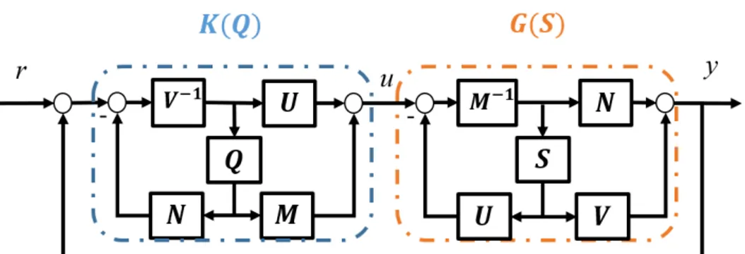
Finally, let’s consider the connection between both parametrizations. The parametrized controller K(Q) described in Eq. 2.3 is connected to the parametrized plant G(S) described in Eq. 2.8. The resulting closed loop is in Fig. 2.2.
Lemma 3. The stability of [G(S), K(Q)] is equivalent to the stability of the positive closed-loop [Q, S] [9].
Hence, this useful linear way of parametrizing either controllers, plants or both is employed to solve many control issues. The rest of the chapter
2.2. Q-BASED CONTROLLER RECONFIGURATION 15
Figure 2.2: K(Q) is the set of all controllers stabilizing the plant G =
M N−1. G(S) is the set of all the plants stabilized by the controller K =
U V−1.
reviews the control applications developed in the last two decades by using
Q, S or both in one system.
2.2 Q-based controller reconfiguration
The main motivation behind controller reconfiguration is performance en-hancement while controlling complex systems with multiple control objec-tives in dynamical environments. Achieving different performance specifi-cations (i.e desired bandwidth, time response, robustness against modeling errors) can be hard while using a single controller. The design process in-evitably requires compromises or trade-offs between various conflicting per-formance objectives. A common solution is designing a controller for each objective, and appropriately switching/interpolating among them in order to accommodate the changing operating conditions, reaching a satisfactory performance level and guarantying overall system stability.
The concept of controller reconfiguration by switching/interpolation dif-ferent controllers is tackled in the literature [14] using difdif-ferent techniques as self-scheduled approach [15], ad-hoc technique [16] or bumpless transfer [17]. Controller reconfiguration using YK parametrization is done by mapping a set of linear stabilizing controllers onto a Q-based controller. Main ad-vantages of using YK parametrization in controllers switching/interpolation are: 1) It allows stable switching between open-loop unstable controllers [18]; 2) Switched/interpolated controllers can be designed and tuned separately using different techniques (H∞, LQR, P ID) [7]; 3) The closed-loop stabil-ity is guaranteed under arbitrary interpolation/switching between different stabilizing controllers [19].
The first application of YK parametrization in controller reconfiguration was in the 80s. Two controllers K1 and K2 were designed to ensure reference tracking and disturbance minimization respectively [20]. Both controllers
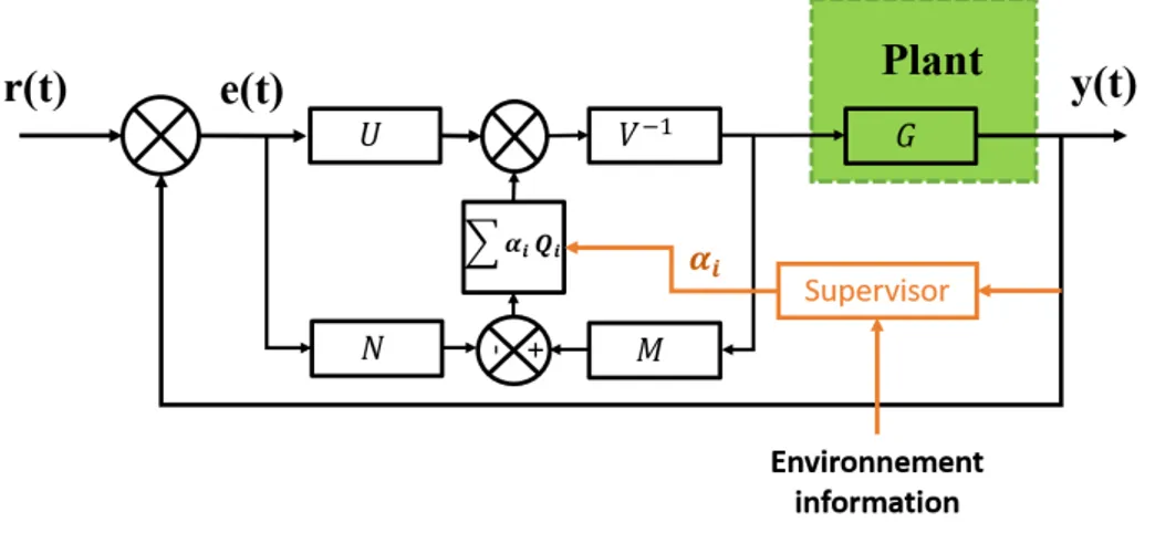
Figure 2.3: Q-based multi-controller scheme.
were mapped in a single controller structure using two YK parameters Q1 and Q2.
After that, the use of YK parameter Q in controller reconfiguration evolved from interpolating two controllers mapping many controllers and switching arbitrary between them. Covering both LTI and LPV frameworks. In this section, YK Q-based controller reconfiguration in both LTI and LPV frameworks are reviewed. Different applications are highlighted show-ing the transfer from theory to practice in real time experimentation.
2.2.1 Control implementation
In LTI control framework, a fixed LTI plant is considered G = N M−1. Several LTI controllers Ki are designed separately, all of them stabilizing the plant G and each controller fulfilling a specific control objective. The set of controllers Ki are mapped in a multi-controller architecture shown in
Fig. 2.3 using YK parameter Q as follow :
K(αiQi) = (U + M i=nX i=1 αiQi)(V + N i=n X i=1 αiQi)−1 (2.9)
Each parameter Qi is computed to connect the controller Kito the nominal controller K = U V−1:
Qi= ( ˜UiV − ˜ViU ) (2.10)
The interpolation signal αi ∈ [0, 1] represents the fraction of the controller Ki that is activated at each instant. αi is computed online by a supervisor that
orchestrates the switching between the pre-designed controllers with respect to a performance metric. It is computed using the system output and the current operating conditions described by the environment information.
2.2. Q-BASED CONTROLLER RECONFIGURATION 17 The goal of the Q-based multi-controller is not only keeping closed-loop stability while switching/interpolation between controllers, but also satisfy-ing a desired level of performance at each instance.
In LPV framework, a LPV plant is assumed G(θ), where θ is a scheduling parameter within a predefined range θ ∈ [θmin, θmax], with a set of critical
design points θi, i = 1, .., n.
In many cases, a LPV plant model is a result of a linearisation technique applied to a non linear system, and θ is tied to the system physics (i.e. speed-dependent on lateral vehicle dynamics using the bicycle model, where the parameter θ is the vehicle speed and its inverse). In each critical design point θ = θi, a controller Ki stabilizing G(θi) is designed to satisfy specific
performance criteria, the controller Ki is thus named local controller. Using YK Q parameter, local controllers can be interpolated in a control scheme that satisfies: 1) stability of the closed-loop including the nonlinear plant (linearized into LPV system) under fast changes of the system param-eter θ; 2) recovering the local controllers Ki in the critical design points;
3) covering a broad class of local controllers as in LTI framework, includ-ing those with multiple inputs/outputs, open-loop unstable dynamics, and controllers with different orders and designed by different techniques (H∞, PID, LQR).
Q-based multi-controller structure for LPV plant is designed following the steps: first, a nominal controller K0(θ) is designed to stabilize the LPV
plant over the range [θmin, θmax] without any performance specification (not
necessarily LPV controller). Then, local controllers Ki(θi) can be designed
to achieve high performance in critical operating points. Once controllers are designed, they need to be decomposed to LPV coprime factors satisfying a LPV double Bezout identity as the one in [21]:
G(θ) = N (θ)M (θ)−1= ˜M (θ)−1N (θ)˜ (2.11)
K0(θ) = U0(θ)V0(θ)−1= ˜V0(θ)−1U˜0(θ) (2.12) Ki = UiVi−1 = ˜Vi−1U˜i (2.13)
The set of all controllers Ki assumed stabilizing the LTI plants G(θi); are mapped in a Q-based controller K(θ) = Fl(JK(θ), Q(θ)), where Fl is
a lower fractional transformation of the interconnection system JK(θ) and
Q(θ) (see [7] for details).
The interconnection system JK(θ) includes the nominal controller K0(θ)
stabilizing the LPV plant over the range of θ:
JK(θ) = " U0(θ)V0(θ)−1 V˜0(θ) V0(θ)−1 V0(θ)−1N (θ) # (2.14) and the YK parameter Q is computed to recover the local controllers Ki in
the design point θ = θi using a polytopic system Q(θ) formed by Qi and a selected weighting function α = f (θ) such as:
Qi = ( ˜UiV0(θi)− ˜ViU0(θi)) (2.15)
The stability of the Q-based LPV controller is proved using a common Lyaponov function all over the range of the parameter θ [22].
An important consequence of using the YK LPV framework is that LTI design techniques can be adopted for LPV plants too.
2.2.2 Applications
YK parametrization Q in LTI controllers switching/interpolations has been used in different applications requiring multiple control objectives.
Related to LTI, the intrinsic conflict between performance and robust-ness in standard feedback loop is tackeled in in [19], a Q-based YK controller is used to control the roll angle of an aircraft. Based on a supervisor [23], the YK controller switches between a high performance controller when the measured angle is not noisy, to a robust controller when there are model uncertainties and external disturbances.
In [24] Q-based controller is used to control two classes of complex sys-tems: Irrigation systems and Hypersonic vehicles with flexible dynamics. Both classes are generally described by hyperbolic partial differential equa-tions. The Q-based controller switches between different LTI controllers to accommodate time-domaine specifications (i.e. peak value of control sig-nal, overshoot). In [25, 26] a method for introducing new components in the control loop in a stable way is presented using the Q-based controller. The controller reconfiguration is illustrated on a livestock stable climate system, where a new temperature measurement becomes available during system operation and a new controller is added to the existent control loop. In [27] a sequential stepwise commissioning controller for a steam boiler is developed, the Q-based controller switches gradually between two stabilizing controllers with different objectives, the primary one is to keep the water level within max and min bounds, and the second control objective is to keep the feed water flow steady. In [28, 29] the Q-parametrization is used in the field of Intelligent Transportation Systems (ITS), the proposed con-trol structure ensure stable switching between Cooperative Adaptive Cruise Control system (CACC) and ACC when the communication between vehi-cles fails. Another application in ITS is provided in [30], a lateral control structure is proposed to deal with different initial lateral error by switching between two controllers with different objectives.
The use of YK parametrization Q in LPV plants is illustrated in different LPV systems. In [22] a parameter varying mass-spring-damper system with varying stifnessis is controlled using Q-based controller. In [21] a nonlinear MIMO plant modeling a quadruple tank system controlling the water height in four tanks using two valves; the plant changes from minimum phase to a non minimum-phase with respect to the operating points (valves values).
2.3. Q-BASED NOISE REJECTION AND VIBRATION CONTROL 19 The Q-based LPV controller switches between a MIMO PID controller de-signed in the minimum phase operating point to an H∞ controller in the non-minimum phase operating point. The Q-based controller shows opti-mal performance in both operating conditions. In [31] the LPV Q-based controller is used in fixed pole assignment application, the Q-based con-troller switches among different concon-trollers to locate the closed-loop poles always at the same place independently of the varying parameter. Thus, the LPV closed-loop achieves the same performance in the range of the varying parameter without loosing stability. In [32] a Q-based LPV controller is de-signed to control a simulated missile autopilot, the system is modeled using a LPV plant with four design points. The LPV Q-based controller achieves higher performance compared to a classical gain scheduling LPV controller.
2.3 Q-based noise rejection and vibration control
The problem of noise rejection and vibration control is widely studied in control systems. Such imperfections in control structures are often due to hardware problems (i.e. signal acquisition in sensors, delays in actuators) or environmental disturbances (i.e. external vibrations).Disturbance and noise rejection have been tackled using different tech-niques: Pole placement [33], output sensitivity shaping [34], H∞ [35] and linear matrix inequality (LMI) approach [36].
YK parametrization is used in noise rejection and vibration control through Q-based controller adaptation. Since the plant is assumed known and constant with eventual small variations, disturbance and noise can be handled just by Q modification.
The first application of YK parametrization in disturbance rejection was in 1992 where a feedback controller that can achieve: closed-loop stability; a unit step response and a known sinusoidal disturbance rejection [37] was designed. Authors used the relation between the sensitivity function of the closed-loop and YK parameter Q to design the required parametrized con-troller. After that, the design of YK parameter Q evolved from offline to online and adaptive design, covering feedback and feedforward implementa-tions.
This section presents the advantages of using YK parametrization both in adaptive feedback configuration as well as in adaptive feed-forward com-pensation schemes. Recent developments and applications are gathered in a non exhaustive list.
2.3.1 Control implementation
During the last two decades, the use of YK parameter Q in noise and dis-turbance rejection evolved from rejecting a known noise signal with a given
frequency to variable known and unknown spectral characteristics. Differ-ent implemDiffer-entations of the YK parameter Q are proposed according to the disturbance type [38].
When a non-correlated measurement with the disturbance signal is avail-able, adaptive feedback controller (see Fig. 2.4) is used. If the disturbance structure is a priori known (i.e. single frequency signal) the adaptation is direct, otherwise it is indirect.
In direct feedback adaptation, the objective is to directly estimate YK parameter Q which minimizes the disturbance effect without affecting closed-loop stability. This is possible since the disturbance structure is known, thus allowing to define the order of Q. According to [39] two coefficients in the polynomial Q are enough to characterize the frequency of an unknown sinu-soidal disturbance. Parameters of the Q filter are adjusted online by min-imizing an adaptation error describing the mismatch between the response of the theoretical system model and the disturbed measured response. Error minimisation requires using Parametric Adaptation Algorithm (PAA) [40].
In indirect feedback adaptation, the objective of noise attenuation is reached in two steps: 1) identify the disturbance structure by building a disturbance observer (DO); and 2) design a feedback controller achieving different attenuation levels in the frequency domain (not necessarily total rejection as in direct adaptation), by shaping in real time the output sensi-tivity function to a desired one, assigning an amount of attenuation for each narrow-band disturbance. The updated controller is computed by solving the Bezout equation, the use of YK parametrization allows to reduce the computation load since it simplifies the optimized error equation [41].
Successful application on rejecting unknown and time varying multi-ple narrow band disturbances on active suspension test bench is published in [42]. The proposed benchmark validates comparatively seven various ap-proaches to adaptive rejection of multiple narrow-band disturbances in ac-tive vibration control. Interestingly, all the approaches can be interpreted as YK parametrization of a special kind. The seven approaches has sev-eral differences from a methodological point of view: 1) Plant factorization method; 2) The disturbance observer based signal (i.e. input error, output error, equation error); 3) Type of Q filter (i.e. FIR, IIR, combination of both FIR and IIR and others); 4) Nominal controller design (i.e. H2, LQR, pole placement); 5) Disturbance rejection technique (i.e. Output sensitivity shaping, inverse model principal); 6) Type of adaptation (i.e. direct, indi-rect); 7) Error signal for adaptation. The seven approaches are tested in simulation and in practice using a test bed based in an inertial actuator and equipped with a shaker and a measurement of the residual force. Results are evaluated according to following criteria: 1) Control performance in both steady state and transient responses; 2) Robustness is evaluated with re-spect to plant uncertainties (low damped complex zeros non identified in the test-bed), this criteria is assessed by defining a normalized performance
2.3. Q-BASED NOISE REJECTION AND VIBRATION CONTROL 21
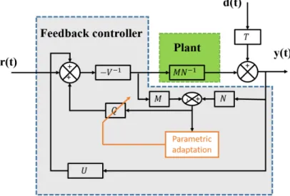
Figure 2.4: YK feedback controller scheme: the disturbance propagates through the plant T (so called primary path) and the compensation is done through the plant (M N−1) driven by a feedback compensator. [39]
loss between simulation and practical results; 3) The complexity of each method is evaluated using the measurement of the Task Execution Time (TET) is used. This benchmark provides useful insights for choosing the best approach according to given constrains.
When a correlation exists between the disturbance signal and measure-ment, adaptive feedforward controller is used to compensate broad-band disturbances [44].
The main problem in adaptive feedforward control is the internal pos-itive feedback between the compensation system and the reference source that can cause instabilities (see Fig. 2.5) while adapting the controller pa-rameters. The use of the YK parametrization allows the separation between the stabilization of the internal positive feedback problem and the opti-mization of the feedforward controller parameters minimising the residual noise [45]. The feedforward controller can be designed either using direct adaptive configuration or indirect one; In indirect configuration, the con-troller is estimated over a certain time horizon. Then, the YK parameter Q is deduced to switch from the nominal controller to the updated one (see Section 2.2). In direct configuration, a tuning algorithm is developed to define design adaptive Finite Impulse Response (FIR) or Infinite Impulse Response (IIR) compensators as a YK parameter Q and update directly the controller that minimizes the residual noise [38].
The main difference between the use of feedback and feedforward im-plementations relies on the availability of a measurable signal correlated with the noise or the vibration. Also, adaptive feedback implementation is
Figure 2.5: YK feedforward controller scheme: the disturbance d(t) prop-agates through T (so called primary path) and its effect is compensated through the plant (M N−1) driven by a feedforward compensator. The input to the feedforward compensator is the sum of the image of the disturbance and of the internal positive feedback. [43]
more dedicated to single and multiple narrow-band disturbances and vibra-tions rejection. While adaptive feedforward implementation is particularly dedicated to the attenuation of broad-band noise with unknown and time-varying characteristics [43].
2.3.2 Applications
The use of YK parametrization Q in adaptive noise and vibration rejec-tion context covered different applicarejec-tions requiring high control precision and low noise sensitivity as: wafer scanning in semiconductors [46], data storage systems (reading/writing) [39, 47, 48], mechatronics [49], active sus-pension systems [40,50] and biochemistry [51] where the regulation problem is to maximize the biomass productivity in the fed-batch fermentation of a specie of yeasts and the cell growth is an undesirable consequence and considered as an unstable disturbance. The specificity of this application is that the YK parameter Q represents an extra degree of freedom in the controller considering the disturbance model, and allowing the rejection of this unstable.
A YK based feedback controller rejecting bounded disturbances is ex-tended to cover LPV systems using LMI computation toolbox in [52].
Those encouraging experimental results showed how YK can be used to deal with different disturbance types rejection. Table 2.1 presents an overview with the different practical applications, including details on the disturbance type and YK controller design.
2.4. S-BASED CLOSED-LOOP IDENTIFICATION 23 Table 2.1: Applications on the use of YK in disturbance rejection.
Noise Controller Applications
No information is available on real time Feedback controller using a DO (Indirect adapation)
Data storage system [48]: - Multiple narrow band disturbance.
- Controller is computed online to filter the observed disturbance. - Q is deduced as a weighted notch filter to switch to the final controller.
Feedback controller with PAA (Direct adaptation) -YK parameter Q is computed by the
PAA to mininize the noise effect.
Acoustic duct [53]:
- Single varying sinusoidal disturbance. - Q parameter is a FIR with 2 parameters. Active suspension [50]:
- Single varying narrow band disturbance . Blu Ray Disc [39]:
- Repetitive narrow band disturbance . Road profiler [40]:
- The road profile is modeled as a disturbance with time varying charachteristics acting on the vehicle dynamics .
- The estimated Q polynome represents the road profile Correlated measurement
is available on real time
Feedforward controller using DO (Indirect adaptation)
Astronomical Telescope [54]:
- Low frequency large-magnitude narrow-band disturbances. - Different Q designed offline are compared experimentally . Feedforward controller with PAA
(Direct adaptation)
Duct active noise test-bench [43]: - Broad band disturbance.
- Comparaison between IIR and FIR YK parameter Q is provided. - FIR Q filter is more robust.
2.4 S-based closed-loop identification
System dynamics identification is an essential step for any control design. Initially, identification techniques were developed to carry out open-loop identification. However, in practice many plants cannot be easily operated in open loop for carrying an identification protocol for different reasons (i.e. open loop unstable, integrator behavior). Additionally, some controllers may be already in place without the option to be disconnected to the plant, being the close loop identification the only way to obtain a better model for either designing a new controller or re-tuning the exiting one in an adaptive way. Several theoretical tools for closed loop identification are proposed in the literature [55]. Dual YK parameterization S has been used to cope with some of the problems related to closed-loop identification of system dynamics [56].
In order to clarify the differences between both, and to see in which case is useful to use the YK-based closed-loop identification, this section compares a general open-loop identification setup with a general closed-loop identification setup, highlighting the advantages of using the second one. Origin and evolution of this dual YK-based identification scheme are also explained. Finally, some practical applications are provided in subsection 2.4.2.
2.4.1 Identification scheme
The identification procedure is the first step to achieve the linear models of the unknown systems. First let’s consider two kinds of identification setups: • Open-loop identification: This method used when the control input
u and measurement noise n are assumed to be non-correlated. Some
control input u can be applied to the system G, obtaining the corre-sponding output y with noise n:
y = Gu + n (2.16)
If measurements u and y are available, many open-loop identifica-tion schemes (Auto Regressive model with eXternal inputs ARX [57], PBSIDopt [58] ...) can be used to find cross-correlation with u, and estimate Gi
Φyu= GΦuu+ Φnu (2.17)
where Φnu= 0 as n and u are independent.
• Closed-identification: This method is used when the control loop is closed and the system is connected to a controller K, where reference signal r and output noise n are non-correlated. Equation 2.17 remains, but Φnuis not zero, as n is feedback through the controller K affecting the control signal u. Cross-correlation expression results:
Φyu= GΦuu− (1 + K∗G∗)−1Φnn (2.18)
where the superscript * denotes complex conjugation on the jω axis. The identification process becomes complex. Even if Φnn is really small, Eq. 2.18 denotes that G should be stable, which could not be the case. As a solution, one could seek to estimate the closed-loop transfer function from the reference signal r to y: P = KG(1+KG)−1. Once an estimation of the CL function is obtained ˆP , an estimation
of the real system ˆG would be:
ˆ
G = Pˆ
K(1− ˆP ) (2.19)
but problems could occur if K has some unstables poles/zeros; the estimation could result again unstable.
It is then logical to disconnect the plant in order to carry out an open-loop identification. But there will be cases in which this is not possible: The plant is unstable, disconnecting the plant supposes a great economic cost, the feedback controller is embedded in the system, or an online estimation of the system is needed for controller improvement.
2.4. S-BASED CLOSED-LOOP IDENTIFICATION 25 Between open-loop and closed-loop identification methods, it is well-known that for model-based control design, closed-loop identification gives better performance [59]. However, one needs to deal with its associated difficulties: Linear matrix inequality (LMI) feasibility [60], linear fractional dependence with respect to measured variables [61] or linear-deterministic subspace selection [62] are some examples picturing these difficulties.
The dual YK-parameterization S is used in closed-loop identification as a solution to suppress its difficulties [63,64] (called Hansen scheme). Specifi-cally, given a LTI initial model and a controller, the key idea was to identify the dual YK S instead of the plant model G. Interestingly, the identification of S was a standard open-loop identification problem, so a closed-loop prob-lem is transformed into an open-loop-like probprob-lem. Several analysis demon-strated how the obtained model with the Hansen scheme is superior than an open-loop identification solution for subsequent control design [65] [66].
The original LTI Hansen scheme has been modified and extended to deal with more complex systems:
• Related to LTI, [67] presented a modification able to tune the order of the resulting model given by the Hansen scheme. The idea is to have control over the possible order explosion when the model is employed in any adaptive control law; [7] extended the scheme when connected to a controller with the YK filter Q. Robust stabilization results con-necting K(Q) and G(S) are here useful for unbiased identification of
S when a YK parameter Q is applied; [68] modified the original
iden-tification scheme in order to avoid the use of indirect excitation signals in reference and feedforward inputs. It imposes any desired excitation signal for the identification of S without affecting those.
• The Hansen scheme has been also extended to LPV systems [69] [70]. Interesting results are obtained in terms of stability, and doubly co-prime factors based on these scheduling parameters of the LPV system. • Related to system with a changing number of inputs/outputs, [71] modified the Hansen scheme in order to deal with new measurements that become available during online operation. New dynamics related to new sensors are identified by the dual YK parameter S.
• A non-linear initial model G0 connected to a stabilizing controller K0 is considered in [72] [73].
2.4.2 Applications
Closed-loop identification of a piezoelectrically controlled gas bearing using the modified version of the original Hansen scheme in [68] was presented in [74]. It highlights the need of closed-loop identification since the system is unstable without feedback control.
Related to LPV, simulation results of coupled dynamics identification in heat distribution systems with different valve settings are in [70]. Cor-responding experimental results are in [75]. Specifically, strong coupling dynamics in the network are identified after a consumption increment. On the other hand, experimental results related to low-speed longitudinal vehi-cle dynamics are presented in [76].
Concerning the identification of new sensors added to a system, simula-tion results with a livestock stable ventilasimula-tion system were presented in [71]. A new temperature sensor is added in order to regulate better the tempera-ture of the stable. The proper identification of the sensor allows the correct adaptation of the corresponding temperature control system.
2.5 (Q,S)-based adaptive control
As already stated, the linearity of Q within the closed-loop function fa-cilitates optimization over the class of all stabilizing controllers. The YK parameter Q allows to achieve various control performance objectives. Every single controller could be augmented with Q and results in another controller having different control objectives. The assumption the implementation of YK-based multi controller as presented in section 2.2 is that the pant model is known and the controllers are predefined.
In this section, Q is seen as a stable filter that can be optimized/adapted offline or online in order to improve the system performance depending on the desired response. Also, this section reviews the methods that adapt the parameter Q using the parametrized plant G(S), where the augmentation
S contains the dynamics that are not modeled in the nominal plant G.
Notice that this differs from the solution in section 2.2, where controllers for different system responses are designed a-priori, switching between them depending on any intelligent algorithm that considers the system environ-ment.
2.5.1 Control implementation
There are many different ways of designing the corresponding Q to adapt the controller to the specific system situation. This section summarizes some of them highlighting in which situations each solution should be employed.
Q, S or both are employed depending if an identification process would be
needed to correctly modify the corresponding controller.
• Q-offline optimization: The most basic approach used to compute YK parameter Q in designing Q-based adaptive controllers is offline opti-mization. The idea is to design a controller in the class of all stabilizing controllers. Different control performance objectives can be set in or-der to optimize Q. These performance requirements can be described
2.5. (Q,S)-BASED ADAPTIVE CONTROL 27 in time or frequency domain. System norms in the frequency domain is directly related toH∞ and H2 concepts. For instance, penalization
of the energy of the tracking error and control energy are examples of
H2 control; while penalizing the maximum tracking error subject to
control limits is an example ofH∞ control. Specifically, in [77], loop recovery was achieved by augmenting the original H2 controller with the additional filter Q. They showed how full or partial loop recovery may be obtained depending if minimum or non-minimum phase plants are considered. Improvements over standard loop recovery techniques were obtained.
• Q-online optimization: Offline optimization evolved to an online modi-fication of Q without any identimodi-fication algorithm. This is the idea pre-sented in [78]. Q’s optimization process is based on root-mean-square signals measures. A state-space relationship between a nominal plant with disturbances and an observer-based feedback controller K(Q) is obtained. The order of Q should be fixed depending on the applica-tion. A steepest descent algorithm is used to obtain the parameter values of the predefined YK parameter Q, so the error is minimized from the disturbances on the system. However, the method is valid when the uncertainty is limited but unknown.
An identification algorithm is needed when there is a large model-plant mismatch. This identification algorithm is directly related to the dual YK parametrization in three different methods: Iterated, nested and indirect adaptive control designs.
For iterated and nested solutions [7], K(Q) is seen as a controller where
Q changes online, as well as G(S) is seen as a nominal plant with an
aug-mentation related to unmodeled dynamics. The process is as follows: First, a nominal controller K is designed for a nominal plant G. Plant-model mismatch is identified through the dual YK parameter S, and then the aug-mented controller Q is designed to optimally control S to some performance criteria.
• In iterative control design, unmodeled dynamics represented by S are identified by using the Hansen scheme with Q inclusion presented in section 2.4. It avoids bias problems in the identification process. S is used in an iterative manner for finding the Q that improves the per-formance criteria. Iteration is needed as the value of S is not initially reliable or due to new deficiencies in the model. In each iteration the order of the controller increases as S includes the applied Q, followed by a control update step.
• In nested control design, successive S are identified on the residual mismatch between model and plant. An external signal needs to be
injected in order to identify the new S. In each step the model of the system is updated. This new model is then taken into consideration for obtaining a new Q, until the performance criteria is fulfilled. This kind of structure is practical when a plant is described by different recursive fractional forms [79].
Although, iterated and nested solutions look sufficient for any system uncer-tainty, algorithms are conceived for a time-invariant Q property. In order to deal with a time-variant Q, an adaptive version of nested control was proposed in [80], called in literature indirect adaptive control.
• In indirect adaptive control design, a fixed structure of Q is created. Parameters in Q are the changing ones, depending on the model-plant mismatch identified by S. As Q varies with time, the unbiased identi-fication provided in the iterated solution is no longer available. Exter-nal excitation sigExter-nals are needed in order to identify S, and this could compromise the control performance. For solving so, two different so-lutions were targeted: two time scales in the adaptive algorithm was proposed in [81], a faster one for the identification of S, and a much slower for the adaptation of Q; and Q augmentation with a filter in the frequency of the excitation signals needed for the identification of
S in [7].
2.5.2 Applications
(Q,S)-based adaptive control solutions were used in solving different sys-tems control problems’: [82] used direct Q adaptive control in a hard disk servo system to minimize the maximum position error signal, which is the deviation of the read/write head from the center of the track.
Simulation results of the direct adaptive-Q controller were presented in [83] to illustrate their performance enhancement capabilities when dis-turbances appear on the system. Part of these results were previously val-idated in a 55th order aircraft model with a H2 controller design with Q
augmentations for achieving resonance suppression [7].
Experimental results are in [84] for laboratory-scale model of a district heating system. In the district heating system, as consumers are not happy with the variable supply rate, differential pressure sensors are added to ex-amine the problem. That revealed a performance problem, so control ca-pabilities are added to another pump, improving the initial H2 controller
through the corresponding augmented Q.
2.6 (Q,S)-based fault tolerant control
The key idea of using Fault Tolerant Control (FTC) strategy is to keep the closed-loop system stable while possibly accepting a reduced performance
2.6. (Q,S)-BASED FAULT TOLERANT CONTROL 29 when critical faults occur in the system (i.e. loss of sensors and/ or actua-tors). FTC architectures are mainly based on fault detection and controller reconfiguration techniques [85].
Both YK parameter Q and dual YK parameter S have been used in dif-ferent FTC schemes to handle controller reconfiguration and fault diagnosis respectively.
2.6.1 Control implementation
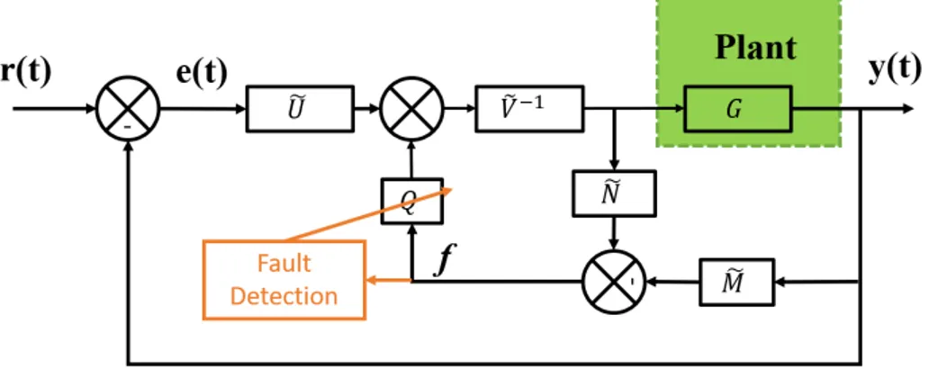
Different FTC schemes only based on YK parameter Q are proposed in the literature [86]; in that case, Q is applied to the controller reconfiguration, while the fault detection part is developed based on some coprime factors. In the FTC scheme depicted in Fig. 2.6, f is the fault diagnosis signal calculated as:
Figure 2.6: Q-based fault tolerant control scheme.
f = ˜N u− ˜M y (2.20)
When there is no fault, the plant has the same response as the nominal model, which yields to f = 0 and the system is controlled by the nomi-nal controller K = ˜v−1u providing adequate performance. Otherwise, the˜ residual signal f is analysed to detect the current fault [87, 88], and then design the suitable YK parameter Q that modifies the controller in the loop in order to manage the current fault.
Another scheme based on YK parameter Q is proposed in [89]. A FTC architecture is designed to tolerate three possible multiplicative faults. Three Q filters are designed offline according to each fault, when a fault occurs the controller switches smoothly from the nominal one to the fault tolerant one by activating the adequate parameter Q. The extension of this architecture where the number of faults can be changed is proposed in [90]. Q-based FTC architectures handle systems with additive faults, and the controller is directly changed with Q, without consideration of S, and

![Table 4.1 presents results of a study conducted about different YK structures [140]. It shows structures 1 to 8 (S1 to S8) with their bene-fits/drawbacks, specific Q calculation and main reference where the struc-ture could be found](https://thumb-eu.123doks.com/thumbv2/123doknet/2853821.70835/79.892.212.729.743.991/presents-conducted-different-structures-structures-drawbacks-calculation-reference.webp)