3 9080
TJ778 .M41 . G24
no. ;Q
ACTIVE
STABILIZATION OFROTATING
STALLAND SURGE IN A TRANSONIC SINGLE STAGE
AXIAL COMPRESSOR
by
Harald J. Weigl
GTL Report #226
July 1997
ACTIVE STABILIZATION OF
ROTATING
STALL AND SURGE IN A TRANSONIC SINGLE STAGEAXIAL COMPRESSOR
by
Harald J. Weigl
GTL Report #226
July 1997
This research was sponsored by NASA Lewis Research Center, Michelle Bright,
technical monitor.
Active Stabilization of Rotating Stall and Surge in a Transonic Single Stage Axial Compressor
by
Harald J. Weigl
Abstract
Rotating stall and surge have been stabilized in a transonic single-stage axial compressor using active feedback control. The control strategy is to sense upstream wall static pressure patterns and feed back the measured signal to an annular array of twelve separately modu-lated air injectors upstream of the rotor. At tip relative Mach numbers of 1.0 and 1.5, the control achieves a 11% and 3.5% reduction in stalling mass flow respectively. With control, the steady amount of injected air is equal to 3.6% of the design compressor mass flow.
At a tip Mach number of 1.0 the stall inception dynamics and effective active control schemes are similar to results for low-speed axial compressors. The range extension can be achieved by individually damping the first and second spatial harmonics of the pre-stall rotating stall perturbations using constant gain feedback.
The pre-stall dynamics are different at a tip Mach number of 1.5 than at the lower speed. Both one-dimensional (surge) and two-dimensional (rotating stall) perturbations must be stabilized to increase the compressor operating range. At design speed, the instability is initiated by approximately 10 rotor revolutions of rotating stall followed by classic surge cycles. In accord with the results from a compressible stall inception analysis which has been applied to the compressor with actuation and refined based on forced response mea-surements, the zeroth, first, and second pre-stall harmonics each include more than one lightly damped mode which can grow into the large amplitude instability. Forced response testing has identified several modes traveling up to 150% of rotor speed for the first three spatial harmonics. Simple constant gain control cannot damp all of these modes and thus cannot stabilize the compressor at this speed. Robust dynamic control is therefore used to stabilize the multiple modes which comprise thie first three harmonic perturbations in this transonic region of operation. Eigenvalue perturbations are incorporated into an Ho' control design to directly address uncertainty in the dominant eigenvalue stability.
ACKNOWLEDGMENTS
This research could not have been completed without the contributions of many people at MIT and the NASA Lewis Research Center (LeRC). The opportunity to work as part of a diverse team to tackle a complex technical problem has been very rewarding.
I am indebted to the following members of the MIT community:
* My thesis supervisor, Prof. Paduano, for the enthusiasm, insight, and encouragement he has shared throughout this research program.
* The thesis committee members for their guidance and support: Prof. Deyst, Prof. Newman, and Prof. Vander Velde.
" Prof. Epstein, for sharing his knowledge and experience developing high-speed
com-pressor experiments.
" Prof. Greitzer, for his tireless support and interest in this research program.
" The other students who have worked directly on this project: Roland Berndt who
designed the actuator prototype and John Chi who constructed the twelve actuators used during these experiments.
" Luc Frechette, who deserves a great deal of credit for the compressible stall inception
modeling effort. I am indebted to him for his dedication in applying the, theory to this project while patiently teaching me compressor fluid dynamics.
" All of the members of the smart-engines group for their willingness to share their knowledge and time.
" Bill Ames, Viktor Dubrowski, Mariano Hellwig, and James Letendre, for their
assis-tance in constructing the experimental hardware. I am especially indebted to Dr. Gerry Guenette for his help with the total pressure rakes.
* Amit Mehra and Maverick Wong whose assistance with the laboratory computers ensured that this thesis could be completed.
I also am grateful to the following people at NASA LeRC who helped to make this collab-oration a success:
" Michelle Bright, for her constant encouragement, willingness to assist in all aspects of
the research, and friendship.
* Dr. Tony Strazisar, for sharing his expertise in high-speed compressors and enthusiasm for making new ideas work.
" The test facility technical staff who worked patiently to ensure that all of the
exper-imental requirements were satisfied: David Williams, Mike Goin, Barry Piendl, and Rob Bruckner.
Thank you to the students in the Gas Turbine Lab who have helped to make the past few years at MIT rewarding and fun. I will miss the times we enjoyed together such as the not-so-serious discussions during lunch and all of the sports that we always played with enthusiasm if not skill. I am also grateful to Dale and Judy Van Zante for their friendship.
I am indebted to my family for the assistance they have given and sacrifices they have made which have helped me fulfill my goals. I wish to thank my parents and sister for their loving encouragement. This thesis is dedicated to my wife and best friend, Shirley.
This project was funded by NASA under grant NAG3-1457 whose support is gratefully acknowledged.
CONTENTS
List of Figures List of Tables Nomenclature 11 17 19 1 Introduction 231.1 Overview of Modal Compressor Control ... ... 24
1.1.1 Rotating Stall and Surge ... ... 24
1.1.2 Overview of Modal Control ... 26
1.2 Previous Modal Control Research . . . . 29
1.3 Research Objectives . . . . 31
1.4 Other Compressor Control Approaches and Issues . . . . 32
1.4.1 Nonlinear Modeling and Control . . . . 32
1.4.2 Short Length Scale Rotating Stall Inception . . . . 33
1.4.3 Compressor Control with Inlet Distortion . . . . 34
1.4.4 3-D Modeling and Control . . . . 35
1.5 Thesis Overview . . . . 35
2 Experimental Setup 2.1 Test Compressor . . . . 2.1.1 Test Facility . . . . 2.1.2 Compressor Geometry and Performance . . . . 2.1.3 Configuration of Actuators and Sensors . . . .. . . . . 2.2 Steady and Unsteady Sensing . . . . 2.2.1 Steady State Compressor Performance Measurements . . . 37 . . . . . 37 . . . . . 37 . . . . . 38 . . . . . 38 . . . . . 40 . . . . . 41
2.2.2 Unsteady Wall Static Pressure Mea
2.3 Air Injection Actuation . . . . 2.3.1 Initial Actuator Design and Testing
2.3.2 Actuator Assembly, Calibration, an
2.3.3 Models of Actuator Dynamics . . . 2.4 Effects of Steady Injection . . . .
2.5 Data Acquisition and Control . . . .
2.5.1 System Specifications . . . . 2.5.2 Hardware . . . . 2.5.3 Software . . . . 2.6 Experimental Procedure . . . . 2.6.1 Sensor Calibration . . . . 2.6.2 Control Experiments . . . .
2.6.3 System Identification Experiments
surements . . . . 43 . . . . 45 . . . . 45 dOperation . . . . 48 . . . . 49 . . . . 52 . . . . 57 . . . . ... . . . . 57 . . . . . 58 . . . . .. . . . . 58 . . . . . 58 . . . . . 59 .~. . . . . 59 . . . . . 59
3 Compressible Stall Inception Model 3.1 Model Overview . . . . 3.1.1 Low-Speed Moore-Greitzer Model . 3.1.2 Previous Development of the Compre 3.1.3 Conceptual Framework of Compressi 3.1.4 Compressible Model Derivation . . . 61 ssible Model ble Dynamics 3.2 Application of Model to Stage 35 . . . . 3.2.1 Experimental Steady Performance Data . . 3.2.2 Computation of Mean Line Flow Field . . . 3.2.3 Calculating Consistent Model Inputs . . . . 3.2.4 Changes to the Original State Space Model 3.2.5 Computation of Mode Shapes . . . . 3.3 Theoretical Stage 35 Pre-Stall Modes . . . . 3.3.1 First Harmonic Modes . . . . 3.3.2 Zeroth Harmonic Modes . . . . 3.4 Summary of Compressible Stall Inception Theory . . . . . 61 . . . . 62 -. -70 . . . . 71 . . . . 75 . . . . 89 . . . . 90 . . . . 91 . . . . 96 . . . . 98 . . . . 100 . . . . 101 . . . . 102 . . . . 111 . . . . 114
4 Experimental System Identification 115
4.1 Stage 35 System Identification . . . .
4.1.1 Discrete Spatial Fourier Decomposition . . . 4.1.2 Empirical Transfer Function Estimates . . . . 4.1.3 Estimation of Model Parameters . . . . 4.2 Experimental Results . . . . 4.3 Comparison of Theoretical and Measured Dynamics 4.4 Summary of System Identification Experiments . . .
5 Constant Gain Compressor Control
5.1 Overview of Constant Gain Control . . . .
5.2 Stage 35 Constant Gain Control at 70% Speed . . .
5.3 Stage 35 Constant Gain Control at 100% Speed . . . 5.4 Summary of Constant Gain Control Experiments . .
. . . . 115 . . . . 116 . . . . 117 . . . . 125 . . . . 126 . . . . 146 . . . . 154 155 . . . . 156 . . . . 160 . . . . 180 . . . . 184
6 Design of Robust Dynamic Compressor Control Laws 6.1 Compressor Control Design Problem . . . . 6.2 H, Control Law Design . . . . 6.2.1 Overview of H Control Design . . . . 6.2.2 Eigenvalue Perturbation H Design . . . . 6.2.3 Stage 35 100% Speed Spatial Harmonic Controllers . 6.3 Summary of H, Control Design . . . . 187 188 194 194 201 205 217 7 Dynamic Compressor Control Results 7.1 Nominal Operation ... 7.2 Robustness to Steady Operating Point Changes . . 7.3 Modified Actuation Schemes . . . . 7.4 Robustness to Large Amplitude Disturbances . 7.5 Summary of H. Control Experiments . . . . 8 Conclusions 8.1 Overview of Research Program . . . . 8.2 'Summary of Results and Conclusions . . . . 8.2.1 Summary of Active Control Performance . 8.2.2 General Conclusions . . . . 219 . . . . 2 19 . . . . 235 . . . . 238 . . . . 24 1 . . . . 245 247 247 248 249 252
8.3 Recommendations for Future Work . . . . 254 A Actuators: Servo Motor Dynamics and Valve Characteristics 257
B Sheet and 3-Hole Injectors: Injected Profiles, Speedlines, and Internal
Dynamic Model 271
B.1 Injector Design and Wind Tunnel Testing . . . . 271
B.2 Steady Injection Speedlines ... 273
B.3 Injector Dynamic Model ... ... 274
C Compressible Model Developments 281
C.1 Calculation of Steady Blade Row Flow Field . . . . 281 C.2 Actuation Model . . . .. . ... ... . 282
C.3 Mode Shape Calculation ... 285
D Nonlinear Rotating Stall and Surge Control 291
D.1 Overview of Nonlinear Control Law ... 291 D.2 Nonlinear Control Results ... 293
LIST OF FIGURES
Examples of rotating stall and surge . . . . Compressor operating maps with and without control . .
Schematic of compressor feedback control . . . . Flow field perturbation spatial harmonics . . . . Example of two first harmonic modes . . . ... . . . .
Schematic of NASA LeRC compressor test facility . . . .
Stage 35 casing configuration . . . ... . . . . Stage 35 test section . . . . Servo motor transfer function . . . . Injector Helmholtz resonator dynamics . . . . Phase lag due to convective time delay . . . . Total-to-total pressure ratio compressor characteristics Total-to-static pressure ratio compressor characteristics
Schematic of compression system . . . . Schematic of first harmonic incompressible mode shape. . Two-dimensional, compressible flow over a wavy wall . . .
Schematic of a first harmonic compressible' mode shape. Model of the blade rows in compressible model . . . . Schematic of compression system for compressible model . 1-1 1-2 1-3 1-4 1-5 2-1 2-2 2-3 2-4 2-5 2-6 2-7 2-8 3-1 3-2 3-3 3-4 3-5 3-6 3-7 3-8 3-9 3-10
Comparison of speedline measurements and mean line calculations Steady model inputs . . . . Theoretical first harmonic modes . . . . First harmonic static pressure mode shapes at 70% speed . . . . .
. . . . 25 . . . . 26 . . . . 27 . . . . 28 . . . . 29 . . . . 38 . . . . 40 . . . . 41 . . . . 51 . . . . 51 . . . . 52 . . . . 54 . . . . 56 . . . . 63 . . . . 67 . . . . 72 . . . . 73 . . . . 74 . . . . 76 94 98 105 106
3-11 First harmonic static pressure mode shapes at 100% speed . . . 3-12 First harmonic axial velocity mode shapes at 70% speed . . . . 3-13 First harmonic axial velocity mode shapes at 100% speed . . .
3-14 3-15 4-1 4-2 4-3 4-4 4-5 4-6 4-7 4-8 4-9 4-10 4-11 4-12 4-13 4-14 4-15 4-16 4-17 4-18 4-19 4-20 4-21 4-22 4-23 4-24 4-95 .107 .108 .109 .111 .. .. 113
Effect of inlet duct length on first harmonic modes . . . . Theoretical zeroth harmonic modes . . . . Block diagram of plant transfer function . . . . Diagram of open-loop system identification . . . . Diagram of closed-loop system identification . . . . Zeroth harmonic ETFE at 70% speed, 11.07 kg/s . . . . . Zeroth harmonic ETFE at 70% speed, 10.79 kg/s . . . . . Zeroth harmonic identified eigenvalues at 70% speed . . . First harmonic ETFE at 70% speed, 11.07 kg/s . . . . First harmonic ETFE at 70% speed, 10.79 kg/s . . . . First harmonic identified eigenvalues at 70% speed . . . . Zeroth harmonic ETFE at 100% speed, 19.40 kg/s . . . . Zeroth harmonic ETFE at 100% speed, 18.54 kg/s . . . . Zeroth harmonic ETFE at 100% speed, 18.09 kg/s . . . . Zeroth harmonic identified eigenvalues at 100% speed First harmonic ETFE at 100% speed, 19.36 kg/s . . . . . First harmonic ETFE at 100% speed, 18.56 kg/s . . . . . First harmonic ETFE at 100% speed, 18.09 kg/s . . . . . First harmonic identified eigenvalues at 100% speed . . . First harmonic closed-loop ETFE at 100% speed, 17.75 kg Second harmonic ETFE at 100% speed, 18.52 kg/s . . . . Second harmonic ETFE at 100% speed, 17.86 kg/s . . . . Second harmonic ETFE at 100% speed, 17.70 kg/s . . . . Second harmonic identified eigenvalues at 100% speed . . Power spectrum of first SFC at 100% speed . . . . First harmonic ETFE at 89% speed, near stall . . . . Power spectrum of firct SFC at 89% speed... 4-26 First harmonic ETFE at 100% speed, with whirling shaft 145 . ...118 . ...119 . ...122 . ...129 . ...130 . ...130 . ...131 . ...132 . ...132 . ...134 . ...135 . ...135 . . . .136 . . . . 137 . . . . 138 . . . . 138 . . . . 139 / . . . . 139 . . . . 140 . . . . 141 . . . . 141 . . . . 142 . . . . 143 . . . . 144 . . . . 145
4-27 Power spectrum of first SFC at 100% speed, with whirling shaft . . . . 146
4-28 Effect of rotor speed on first harmonic transfer functions . . . . 147
4-29 Comparison of theoretical and measured zeroth harmonic eigenvalues. . 150 4-30 Comparison of theoretical and measured first harmonic eigenvalues ... 151
4-31 Comparison of theoretical and measured zeroth harmonic transfer functions at 100% speed . . . . 153
4-32 Comparison of theoretical and measured first harmonic transfer functions at 100% speed . . . . 153
5-1 Block diagram of Stage 35 feedback control system . . . . 156
5-2 Block diagram of Stage 35 spatial harmonic control . . . . 157
5-3 Schematic of constant gain rotating stall control .... . . . . 159
5-4 70% speed constant gain control speedline (3.6% level of steady injection) . 161 5-5 70% speed throttle ramp without control (3.6% level of steady injection) . . 163
5-6 70% speed rotating stall without control (3.6% level of steady injection) . . 164
5-7 70% speed throttle ramp with n = 1 control (3.6% level of steady injection) 166 5-8 70% speed root locus with n = 1 control (3.6% level of steady injection) . . 167
5-9 70% speed throttle ramp with n=0, 1, and 2 control (3.6% level of steady injection) . . . . 169
5-10 70% speed fully developed rotating stall (3.6% level of steady injection) . 170 5-11 70% speed unsteady actuator position (3.6% level of steady injection) . . 171
5-12 70% speed constant gain control speedline (1.5% level of steady injection) 173 5-13 70% speed throttle ramp without control (1.5% level of steady injection) . 174 5-14 70% speed throttle ramp with n = 1 control (1.5% level of steady injection) 175 5-15 70% speed throttle ramp with n=0, 1, and 2 control (1.5% level of steady injection) . . . . .. ...176
5-16 70% speed fully developed rotating stall (1.5% level of steady injection) . . 178
5-17 70% speed unsteady actuator position (1.5% level of steady injection) . . . 179
5-18 100% speed throttle ramp without control (3.6% level of steady injection) . 182 5-19 100% speed throttle ramp with n = 1 control (3.6% level of steady injection) 183 5-20 100% speed root locus with n = 1 control (3.6% level of steady injection) . 184 6-1 Zeroth harmonic design model . . . . 191
. . . . 192 6-3 6-4 6-5 6-6 6-7 6-8 6-9 6-10 6-11 6-12 6-13 6-14 6-15
Second harmonic design model . . . . Robust control problem . . . .
Mixed sensitivity problem . . . . Mixed sensitivity with eigenvalue perturbations . . . .
Ko(s) H. control law . . . .
Ku(s) H, control law . . . .
K12(s) H. control law . . . . K2(s) HO control law . . . .
Ko continuous and discrete-time controller dynamics
K 1 continuous and discrete-time controller dynamics
K12 continuous and discrete-time controller dynamics
K2 continuous and discrete-time controller dynamics
Comparison of identified and desired K1 1 dynamics.
7-1 100% speed HO control speedline (3.6% level of steady injection) . . . . 7-2 100% speed throttle ramp without control (3.6% level of steady injection) . 7-3 100% speed throttle ramp with Ko(z) (3.6% level of steady injection) . . . 7-4 100% speed throttle ramp with K1 1(z) (3.6% level of steady injection) . . .
7-5 100% speed throttle ramp with Ko(z) and K1 1(z) (3.6% level of steady in-jection) . . . .
7-6 100% speed throttle ramp with Ko(z), K1 1(z), and K2(z) (3.6% level of
steady injection) . . . .
7-7 100% speed throttle ramp with Ko(z), K12(z), and K2(z) (3.6% level of
steady injection) . . . . 7-8 Extrapolated first harmonic poles at 17.72 kg/s . . . .
7-9 First set of fully developed classic surge data . . . .
7-10 Second set of fully developed classic surge data . . . . 7-11 Third set of fully developed classic surge data . . . . 7-12 100% speed unsteady actuator position . . . .
7-11 95% speed H control speedline (3.6% level f t n
j
)...7-14 100% speed throttle ramp with six actuators . . . .
. ...193 . ...195 . ...201 . ...203 . ...211 . ...212 . ...213 . ...214 . ...215 . ...215 . ...216 . ...216 . ...217 221 224 225 226 227 228 229 230 232 233 234 235 239
7-15 100% speed controlled speedline with 1-sided actuation 7-16 Recovery from fully developed classic surge...
7-17 Recovery from rotating stall and surge disturbances
A-1 Actuator #1 A-2 Actuator #2 A-3 Actuator #3 A-4 Actuator #4 A-5 Actuator #5 A-6 Actuator #6 A-7 Actuator #7 A-8 Actuator #8 A-9 Actuator #9 A-10 Actuator #10 A-11 Actuator #11 A-12 Actuator #12 . . . 243 . . . 244 . . . . 258 . . . . 259 . . . . 260 . . . . 26 1 . . . . 262 . . . . 263 . . . .. . . 264 . . . . 265 . . . . 266 . . . . 267 . . . . 268 . . . . 269
B-1 Schematic of 3-hole and sheet injectors . . . B-2 Injector steady momentum flux distribution B-3 Compressor characteristics with four injector B-4 Schematic of Helmholtz resonator model . . . . . . 272
. . . . 277
configurations . . . . 278
. . . . 279
D-1 Comparison of development of first harmonic perturbation . D-2 Averaged first harmonic perturbation amplitudes . . . . D-3 Actuator motion with nonlinear control . . . . 295 296 296 . . . . 240
LIST OF TABLES
2.1 2.2 2.3 2.4 2.5 2.6 2.7 4.1 4.2 4.3 5.1 5.2 5.3NASA Stage 35 geometry . . . . 39
NASA Stage 35 design parameters . . . . 39
NASA Stage 35 steady flow field measurements . . . . 42
Other steady performance measurements . . . . 43
NASA Stage 35 unsteady wall static pressure sensors . . . . 44
Total actuator mass flow rates . . . . 49
Data acquisition and control inputs and outputs . . . . 57
70% speed system identification . . . . 100% speed system identification . . . . Comparison of theoretical and measured Stage 35 eigenvalues . . . . 70% speed constant gain control experiments (3.6% level of steady injection) 70% speed constant gain control experiments (1.5% level of steady injection) 100% speed constant gain control experiments (3.6% level of steady injection) 128 133 148 160 172 180 6.1 H, Control Design Constraints . . . . 207
7.1 100% speed Ho, control experiments . . . . 220
7.2 100% speed H. control experiments with less steady injection . . . . 236
NOMENCLATURE
Symbols
a Speed of sound (v/yRT)
A Annulus area
B Nondimensional surge stability parameter
B Upstream potential wave coefficient C Downstream potential wave coefficient
D Vortical wave coefficient
E Entropic wave coefficient
M Mach number (V)
n Harmonic number
P Pressure
r Mean radius
R Gas constant for air
s Laplace transfrom variable
t Time
T Temperature
U Wheel speed
V Velocity
W Blade passage relative velocity
X Axial coordinate
Greek Symbols
an Upstream potential wave propagation coefficient
0
Relative flow angle#n
Downstream potential wave propagation coefficientXn Convecting wave coefficient
7 Ratio of specific heats
A Eigenvalue
0- Eigenvalue real part (growth rate) w Eigenvalue imaginary part (frequency)
W/, Relative total pressure loss coefficient
Q Rotor frequency
<$ Flow coefficient
(-)
p Density
Tp Total pressure loss lag time constant 7d Deviation lag time constant
0 Tangential coordinate
Blade row stagger angle
Operators, Superscripts, and Subscripts
6(-) Small perturbation
() Mean value
() Spatial Fourier coefficient (.) Derivative with respect to time
() Complex conjugate
F(s) Laplace transform of f(t)
(-)a Real part
(-)a Imaginary part
() Relative frame value
() Axial component
() Tangential component
()tip Blade tip
()k Blade row and inter-blade row gap number
(-n nth spatial harmonic value
() Stagnation (or total) quantity
()nd Non-dimensional value
Acronyms
ETFE Empirical transfer function estimate
MIMO Multi-input, multi-output
SFC Spatial Fourier coefficient
SISO Single-input, single-output
1-D One-dimensional (x direction)
2-D Two-dimensional (x and 0 directions)
3-D Three-dimensional (r, x, and 0 directions)
Matrices and Vectors
A Matrices denoted by bold uppercase characters
AT Transpose of A
ai ith column vector of A
aij (i, j) entry of A
I Identity matrix
CHAPTER
1
INTRODUCTION
The performance of gas turbine engines is limited by compressor instabilities that occur at low mass flow and high pressure rise. These instabilities, known as rotating stall and surge, have therefore been extensively studied by compressor aerodynamicists for many years. In 1989, Epstein et al. [15] proposed a new approach to the problem: stabilize rotat-ing stall and surge with feedback control. As discussed in the followrotat-ing sections, the field of compressor stabilization has since grown through the cooperative efforts of compressor aerodynamicists and control engineers. Researchers have demonstrated increased operating range on several compressors using a wide array of control analysis and design techniques
[16, 29, 48, 49]. Furthermore, forced response testing and system identification have
pro-vided a better understanding of compressor dynamics, leading to the development of more sophisticated and accurate surge and stall models.
Several issues must be considered as the technology evolves from laboratory test-beds to compressors with the higher rotation speeds and more advanced blade designs found in modern engines. For the.compressor design community, active control is a new approach that requires new modeling and instrumentation techniques. The equations which govern the complex dynamics must be cast into a form applicable to control analysis and design. High bandwidth sensors are required that are sensitive to small flow field perturbations, yet are rugged enough to survive in a high pressure ratio compressor. New actuation schemes are also heeded with the bandwidth and control power to effectively control instabilities. Surge and rotating stall control also poses a rich set of control engineering challenges. Even the most advanced theoretical models are approximations of the complex dynamics
involved. Furthermore, the compressor dynamics change as the operating condition of the compressor varies, and have significant nonlinearities. These complex dynamics must be identified and controlled based on noisy measurements with limited actuator bandwidth and control power.
This thesis extends the current knowledge base of compressor control to stabilizing rotating stall and surge in a transonic axial compressor stage. Also, a newly developed compressible stability model [18] has been verified and refined with forced response measurements. The rest of this chapter describes the research program and discusses its contributions to the current understanding of compressor control. An overview of the modal control approach pursued in this research is given in Section 1.1. Section 1.2 describes previous research efforts on which the high-speed compressor stabilization is based. The objectives of the experiments presented in this thesis are discussed in Section 1.3. For completeness, Section 1.4 discusses some techniques other than modal control that have been demonstrated, as well as some important issues which have not yet been studied and are beyond the scope of this project. Finally, Section 1.5 gives a chapter by chapter overview of this thesis.
1.1
Overview of Modal Compressor Control
This section is divided into two parts. The first gives a basic description of rotating stall and surge. The second part describes the modal control technique which has previously been applied to low-speed compressors and is extended to a high-speed machine in this thesis. This section is intended to give the reader a general introduction to the approach, to provide a backdrop for the research program description which follows.
1.1.1 Rotating Stall and Surge
Figure 1-1 is an illustration of rotating stall and surge. Rotating stall is a two-dimensional
(2-D) instability characterized by a region of reduced air flow in the compressor annulus;
this stalt cell rotates at a fraction of the rotor speed (typically between 20% and 60% of rotor frequency). As shown in Figure 1-1, surge is a lower frequency. one-dimensional (1-D) flow oscillation through the entire compression system. Both instabilities are described in
detail by Greitzer [26].
Rotating Stall Surge
Circumferentially Nonuniform Flow Axially Oscillating Flow
High Flow
Frequency - 50-100 Hz Frequency - 3-10 Hz
Figure 1-1: Examples of rotating stall and surge (from [26]). The spatial structure of rotating stall and surge is illustrated as well as the unsteady pressure transients for both types of instability.
Instability in high-speed axial compressors, such as the one studied as part of this effort, is typically initiated by rotating stall (see for example Tryfonidis et al. [59]). Depending on the compression system geometry and rotation speed, rotating stall may then lead to classic surge as described by Greitzer [25]. Classic surge is a combination of both surge and rotating stall. During the low compressor mass flow portion of the surge cycle, a rotating stall cell is superimposed on the 1-D surge oscillation. The rotating stall cell then clears during the second part of the cycle as the compressor mass flow increases.
A typical operating map of a compressor without control is illustrated in Figure 1-2a.
The compressor map (also referred to as a speedline or characteristic) is a plot of the steady state pressure rise across the compressor versus mass flow at'a fixed rotational speed. The line labeled with points A and D represents the range of stable compressor operating conditions. If the mass flow is reduced below point A, the flow becomes unstable (rotating stall or surge occurs). During rotating stall, the pressure rise drops significantly to point B. The compressor mass flow must then be increased to clear the instability. The hysteresis associated with this recovery is also shown in Figure 1-2a; the mass flow must be increased up to point C before the compressor returns to the nominal speedline.
This loss of compressor performance is a primary reason for avoiding rotating stall and surge. Furthermore, the instability results in large structural loads and potential engine failure. Aircraft engines therefore operate with a safety factor, known as stall margini
'The safety margin for both rotating stall and surge will referred to as stall margin in this thesis.
A D
/4
, B 0 CI Mass Flow A D B' B C Mass Flow(a) Uncontrolled compressor -(b) Stabilized compressor
Figure 1-2: Compressor operating maps with and without control.
(SM) which ensures that the compressor mass flow is well above the stalling mass flow.
However, by running at a high enough mass flow to provide an adequate stall margin, the compressor may operate with a lower pressure rise and less efficiently than desired.
The purpose of compressor stabilization through feedback control is illustrated in Figure
1-2b. With feedback control, the compressor mass flow can be decreased to point A' below
the original instability point, often without a significant loss in pressure rise. This increased operating range translates into increased stall margin.
1.1.2 Overview of Modal Control
This section describes the main components of compressor control. approach is also outlined for low-speed and high-speed compressors.
The modal control
Figure 1-3 shows the three main components for compressor feedback control. Sensors detect th'e perturbations which grow into rotating stall and surge. The control command to stabilize these perturbations is computed with a computer-implemented control law. This control command is fed to a set of actuators which damp the flow field perturbations to
M
0 9L,
prevent full scale rotating stall and surge. As discussed in detail in Chapter 2, wall static pressure sensors were used in this high-speed compressor. A set of injectors blowing high pressure air into the compressor face was used to actuate the system.
Data Acquistion & Actuators - Compressor Control Computer
Sensor Measurements
Figure 1-3: Schematic of compressor feedback control.
In general, it is difficult to apply control modeling and design techniques to fluidic systems due to the presence of both distributed spatial and temporal flow field variations. However, the complex spatial structure of compressor dynamics-can be simplified by decomposing the flow field perturbations into spatial harmonics as illustrated in Figure 1-4. The bottom trace shows an example small amplitude flow field perturbation, at one instant in time, plotted as a function of the circumferential angle. This flow field perturbation can be decomposed into the spatial harmonics shown in the top three traces. Chapter 3 details how the harmonics are computed with a Fourier transform with respect to the circumferential angle.
The top trace in Figure 1-4 shows the circumferentially uniform, zeroth harmonic pertur-bation. This is the perturbation which leads to a 1-D surge instability. The arrows indicate how the zeroth harmonic evolves in time; the magnitude of the pressure oscillates uniformly in the circumferential direction. The second trace is the first harmonic perturbation which is characterized by a sinusoid with a wavelength equal to the compressor circumference. As indicated by the arrows, this entire sinusoidal pattern rotates around the compressor annu-lus. Similarly, the second harmonic (the sinusoidal perturbation with a wavelength equal to half of the compressor circumference) also rotates. These n : 0 rotating harmonic per-turbations lead to rotating stall. Since surge perper-turbations are a subset of the general 2-D harmonics, 'stall' will refer to both rotating stall and surge in this thesis unless specifically noted.
Previous low-speed rotating stall modeling and control efforts (discussed in the following section) are based on this decomposition of small amplitude perturbations into long wave-length harmonics. These spatial harmonics are the eigenmodes of the linearized dynamics
Zeroth Harmonic .. . ... . . . .. . . . ....... . ... .. . .. . . .. .. . .. .. PO() 0--- -- -First Harmonic -11 Second Harmonic P2()
- - - -
- - -
- -
- -
- -
-
1--
2' 0 30 60 90 120 150 180 210 240 270 300 330 360Circumferential Angle (deg)
Figure 1-4: Flow field perturbation spatial harmonics.
for low-speed compressors with uniform inlet flow (no inlet distortion). Since modes are decoupled, each harmonic can be modeled and stabilized independently with linear feed-back control. This approach has been referred to as modal control. However, it is important to distinguish between spatial harmonics and modes. 'Harmonic' refers to a sinusoidal circumferential shape; 'mode' refers to an eigenmode of the linear dynamical system.
Spatial Fourier decomposition is also utilized for the high-speed modeling and control ef-forts described in this thesis (details can be found in Section 1.3 and subsequent chapters). Without inlet distortion, each spatial harmonic (n = 0,1,2...) evolves as a dynamically decoupled system as in the low-speed case. However, each spatial harmonic is not a single eigenmode. Instead, each harmonic is comprised of several lightly damped modes due to compressibility effects. This is illustrated in Figure 1-5, which shows two first harmonic modal perturbations (labeled plo(9) and pu (9)). Although the two waves have the same circumferential structure, they are distinguishable by their amplitudes, circumferential lo-catiUIo, rotational frequencies, and growth or decay rates. h1is MULi-moUal UeUIavior or
com-pressor modeling and control. 0.5 PIO(O) -0.5 -1 30 60 90 120 150 180 210 240
Circumferential Angle (deg)
270 300 330
Figure 1-5: Example of two first harmonic modes.
1.2
Previous Modal Control Research
An overview of previous low-speed modal control experiments is given in this section. The development of the air injectors used for the high-speed compressor research is also outlined.
Surge modeling and control has developed more rapidly than rotating stall control due to the simpler 1-D dynamics. The work of Emmons et al. [14] has led to the development of a surge model which includes the duct upstream of the compressor, the compressor, and the downstream volume (plenum). Greitzer [25] verified this model with a nonlinear simulation of instability in a 3-stage axial compressor. This work established the role of the nondimensional 'B' parameter in determining whether a compressor will surge or stall.
A linearized form of this surge inception model was the basis for several surge control
experiments. Ffowcs Williams and Huang [64] stabilized surge with plenum pressure mea-surements and a loudspeaker mounted in the compressor plenum. Plenum pressure was
- . ... -...
...
-... 1 0.5 Pii() 0 -0.5 1 C -. .. . . -. . ... 360 0also sensed by Pinsley et al. [49]; however, the actuation scheme to stabilize this centrifu-gal turbocharger rig was a valve in the plenum exit duct. Passive surge control has also been demonstrated by Gysling et al. [28]. Instead of using electro-mechanical feedback, a movable plenum wall was tuned (with a spring and a dashpot) to passively damp plenum pressure perturbations. Using the linearized surge model, Simon et al. [54] analyzed the effectiveness of various combinations of sensing, actuation, and linear control laws. At this writing, surge control is being attempted on helicopter gas turbine engines (see for example Borror [5]).
In the area of rotating stall control, an incompressible model, developed by Moore and Greitzer [44], has served as the foundation for several low-speed stabilization experiments. This is a 2-D model which accounts for axial and circumferential flow field perturbations (the flow is assumed to be uniform in the radial direction).2 The linearized formulation of the Moore-Greitzer (M-G) model captures the modal stall inception dynamics (which are localized near the compressor) as confirmed by the work of McDougall [43], Longley [42], and Garnier et al. [21]. Paduano et al. [48] extended the operating range of a low-speed, single-stage axial compressor with independent control of the first and second harmonic modes using constant gain control. Haynes et al. [31] demonstrated similar results on a low-speed, 3-stage compressor. Both of these low-speed compressors rigs (with tip Mach numbers of 0.25) exhibited only rotating stall (no surge). Paduano and Haynes sensed axial velocity perturbations upstream of the compressor and actuated the system with a set of twelve movable inlet guide vanes. Paduano and Haynes also used forced response tests to verify and refine the control theoretic formulation of the M-G model.
A theoretical study to determine the most effective sensing and actuation schemes for
low-speed stall control has been conducted by Hendricks and Gysling [33]. Sensing axial velocity and injecting high pressure air into the compressor-face were found to be the most effective schemes for stabilizing modal perturbations with constant gain feedback. Diaz [12] therefore designed an array of electro-mechanical air injectors for the low-speed compressor rig studied
by Haynes. The subsequent compressor stabilization experiments by Vo [62] confirmed that
injection-can effectively stabilize rotating stall (however, the range extension was not as large
2
The M-G model includes the previously described 1-D, zeroth harmonic dynamics as we" as rotating
harmonics. The model accounts for the nonlinear coupling between surge and rotating stall due to the shape of the compressor characteristic.
as predicted due to modeling limitations). Gysling and Greitzer [29] employed a passive injection system on the single-stage compressor; pre-stall pressure perturbations deflected a set of tuned reed valves to control the amount of injected air.
Hendricks and Gysling's results led to the choice of air injection as the actuation scheme for the transonic compressor experiments described in this thesis . However, modal control in a high-speed compressor imposes severe design constraints on any candidate actuation scheme. These issues have been addressed by Berndt [2, 3] who designed the set of electro-mechanical injectors used in this research (see Chapter 2 and Appendices A and B which give a complete overview of these constraints and Berndt's actuator design and wind tunnel testing). These injectors have the required mass flow rate and bandwidth for high-speed compressor control. As described in Chapter 2, the injectors were run with a mean blowing rate so that positive and negative unsteady actuation could be commanded. As will be shown, steady injection significantly increases the compressor operating range. This behavior has previously been reported by Koch and Smith [38, 39] who investigated the effects of upstream blowing on the stable operating range of a transonic compressor.
1.3
Research Objectives
The purpose of the research program presented in this thesis is to extend the low-speed compressor modal control experiments to a compressor rig with the pressure ratio, mass flow rate, and rotation speed found in modern engines. Recently, extensions to the original Moore-Greitzer model have been made to account for compressibility effects (see Bonnaure [4] and Feulner et al. [18]). This model predicts that there can be multiple lightly damped modes for each spatial harmonic which can grow 'into rotating stall and surge; it serves as the theoretical framework for applying feedback control. Experimental validation and refinement of this model is a key objective of this research. Furthermore, this research tests the utility of Berndt's recently developed air injectors for forced response measurements and feedback control.
To summarize, there are three main objectives of this research program which address the modeling, system identification, and control aspects of this problem:
" Measure the pre-stall dynamics to validate and refine the compressible rotating stall and surge inception model.
" Develop control laws to stabilize the compressor and demonstrate robustness to
changes in the steady compressor operating point and to large amplitude disturbances.
" Experimentally verify the effectiveness of air injection for forced response
measure-ments and control in a transonic compressor.
It should be emphasized that detailed modeling of the steady and unsteady interaction between injection and the compressor is beyond the scope of the research presented in this thesis. The overall impact of steady injection on the compressor performance has been measured and incorporated into the inputs of the theoretical model as outlined in Chapter 3. Similarly, the unsteady effects were measured through overall identification of the compressor dynamics.
The system identification and control experiments were conducted at 70% and 100% design speed (with tip Mach numbers of 1.0 and 1.5 respectively). The two compressor speeds were studied to assess the effect of rotor speed (compressibility) on stall inception in a high-speed compressor.
1.4
Other Compressor Control Approaches and Issues
This section briefly describes three modeling and control approaches which are not based upon decoupled harmonic perturbations. A short discussion of 3-D rotating stall control, which has not yet been demonstrated experimentally, is also presented.
1.4.1 Nonlinear Modeling and Control
The Moore-Greitzer model is a nonlinear model of stall and surge inception, accounting for the influence of the nonlinear compressor characteristic. Once the pre-stall perturbations have grown to a large amplitude, so that linear, small perturbation analysis is no longer
Vtali, t[1 at Evr etonics are no longer decou ped Severa ofathis, uincu g i emen
nonlinear control laws. Behnken used an array of pulsed jet injectors while Eveker utilized a 1-D plenum bleed valve as.actuation. The goal of these nonlinear control approaches was not to extend the compressor operating range. Instead, the hysteresis shown in Figure 1-2 was eliminated so that large amplitude disturbances could not drive the compressor into full-scale rotating stall and surge along the nominal speedline. The linear analysis and control approach presented in this thesis does not have such guaranteed robustness to arbitrarily large perturbations. However, the experimental disturbance rejection tests presented in Chapter 7 do demonstrate recovery from large perturbations using linear control. It is also difficult to separate the effects of the nonlinear compressor dynamics from the limitations of actuator saturation which must be considered for both nonlinear and linear control.
Feulner's 2-D, linear, compressible model has also been extended, by Hendricks et al. [34], to a nonlinear, numerical simulation of rotating stall and surge inception in high-speed compressors. The numerical simulation is based on the same modeling assumptions as the linearized model presented in Chapter 3. The compressible model validation presented in this thesis is therefore also applicable to this more general formulation.
1.4.2 Short Length Scale Rotating Stall Inception
The stall inception and control studies done by Day [9, 10, 11] indicate that growing har-monic perturbations are not the cause of rotating stall in some low and high-speed com-pressors. Day determined that short length scale rotating disturbances can be the source of instability (as opposed to long wave length harmonic perturbations). Short length scale disturbances, sometimes referred to as pips or spikes, are characterized by a region of low mass flow over only a few blade passages; these spike disturbances rotate faster than har-monic waves, at approximately 70% of rotor speed. Day used air injection and a heuristic control approach to cancel pre-stall spikes. Once a spike was detected, air was injected in a predetermined, rotating pattern until the spike was no longer present. There is currently no control theoretic model of spike dynamics; however, detailed computational studies of the local blade row flow (see Hoying [35]) have related the development of spikes to the location of the rotor tip vortex. Gong [23] is also developing a numerical simulation which captures the development of spatial harmonic and short length scale perturbations.
The model-based modal control approach pursued in this thesis is not applicable to such spike instability. However, high bandwidth measurements in this compressor rig have not indicated the presence of spikes at the stall inception point of the uncontrolled compres-sor. All of the stabilization results presented here are based on damping long wavelength sinusoidal perturbations.
1.4.3 Compressor Control with Inlet Distortion
All of the modeling and control efforts that have been described up to this point have
dealt with uniform inlet flow only. However, an important practical consideration is the loss of stall margin due to inlet distortion (for example, the flow into the engine nacelle may separate during high angle of attack maneuvers). Van Schalkwyk [61] has recently addressed this problem on the same low-speed compressor studied by Haynes and Vo.
Van Schalkwyk pursued a model-based approach using the incompressible distortion model of Hynes and Greitzer3 [36]. Van Schalkwyk verified the accuracy of this model through
O OtlL '-A.A % A" U A1 U1.LL. J.JiW,.L 1A41WGi.OLLL C% 11VJA.LJVGL %.L, A.1 i 1GLWo. VJ W 'Pr' C13V -01UJ~.L I, 'J .IrLMU. ULX
operating range with inlet distortion.
The primary difference between compressor dynamics with clean inlet flow and distortion is the coupling of the harmonic perturbations. Uniform flow compressor stabilization is simpler since each spatial harmonic can be modeled and controlled independently. On the other hand, Van Schalkwyk's results indicate that effective feedback control must account for the strong coupling of harmonics caused by distortion.
An interesting challenge that has not yet been pursued is the control of a high-speed com-pressor with distortion. This modeling and control problem includes multiple compressible modes (as described in this thesis) and coupled spatial harmonics.
3
The Hynes-Greitzer model is an extension of the previously described Moore-Greitzer model with distortion.
1.4.4
3-D Modeling and Control
All of the rotating stall research that has so far been described is applicable only to
compres-sors with high hub-to-tip radius ratios. A reasonable modeling approach for such machines is to assume that the flow is uniform radially; this simplifies the problem to a 2-D repre-sentation of the flow field.
Compressor control has not yet been demonstrated on a turbofan (which has a much lower hub-to-tip ratio than the core compressors that have so far been studied). Nevertheless, the study of radial pre-stall perturbations has been the focus of several recent modeling efforts. Gordon [24] has developed a 3-D, linear dynamic model which could be extended to include sensing and actuation. Gong [23] and Hoying [35] have performed numerical 3-D simulations. Also, Feulner's 2-D, compressible model which is the focus of this research, has been extended to include radial flow field variations by Sun [57].
Although the jet injection used in this study is highly nonuniform radially (see Chapter 2 and Appendix B), 3-D analysis and control are not considered in this thesis.
1.5
Thesis Overview
This section gives a chapter by chapter overview of the remainder of this thesis. Chap-ter 2 describes the experimental setup for this research. A description of the compressor test facility, steady and unsteady measurements, the injection actuation, and experimental procedure is provided. Chapter 3 describes the theoretical stall inception model including its previous development, its application to the high-speed compressor rig in this research program, and the predicted eigenmodes, mode shapes, and transfer functions. The theoret-ical model is compared to system identification regults in Chapter 4. Chapter 5 describes the experimental results using constant gain feedback control to stabilize stall at 70% and
100% speed. Chapter 6 outlines the design and implementation of H, control laws. The experimental results with H, control at 100% speed are presented in Chapter 7. Chapter
CHAPTER
2
EXPERIMENTAL SETUP
This chapter gives an overview of the experi-mental hardware, software, and procedures applied to this research effort. Sections 2.1 to 2.4 describe the main experimental hardware: the compressor test-rig, steady and unsteady measurements, and air injection actuation. Section 2.5 discusses the data acquisition and control computer hardware and software. A brief description of the experimental procedures for system identification and control runs can be found in Section 2.6.
2.1
Test Compressor
The compressor test facility, the transonic compressor, and the configuration of the sensors and actuators on the casing are described in this section.
2.1.1 Test Facility
This research was conducted in the NASA Lewis Research Center (LeRC) Single-Stage Axial Compressor Test Facility, an open circuit facility for testing advanced compressor stages; the facility is depicted in Figure 2-1. The compressor, in the test section, is driven
by a 2.2 Megawatt DC drive motor. Atmospheric air is drawn into the facility through an
orifice plate and a plenum chamber upstream of the test section. A straightening screen in the inlet plenum ensures that the flow into the test section is uniform. Downstream of the compressor, the flow is regulated with a sleeve-type throttle valve. The compressor mass
flow rate is controlled by adjusting the exit area of the throttle valve. After passing through the throttle valve, the air flow is eventually exhausted to the atmosphere.
Inlet throttle valves ,
r Flow Or if
ice--Collector throttle valve Gear box , - Collector
Drive motor Test stage r- Plenum
Vacuum exhauster piping
Atmospheric
exhauster piping Flw CD-1091&-H
Flow
Figure 2-1: Schematic of NASA LeRC compressor test facility (from [51]).
2.1.2 Compressor Geometry and Performance
The test compressor, designated as NASA Stage 35, was designed as an inlet stage of an eight-stage 20:1 pressure ratio core compressor. The compressor geometry is summarized below in Table 2.1. Table 2.2 lists some of the overall design parameters for Stage 35. The reader is referred to Reid and Moore [50, 51] for details of the compressor design and blade-element performance measurements. Although the compressor is almost 20 years old, it is representative of the rotation rate and pressure ratio found in current aircraft engines.
2.1.3 Configuration of Actuators and Sensors
A new casing for the test section was designed and built to accommodate the sensors and actuators required for modal stall control. Figure 2-2 shows a cross section of the new
Table 2.1: NASA Stage 35 geometry.
Compressor
Inlet guide vanes None
Number of stages 1
Rotor/stator gap 1.01 cm
Tip radius 25.25 cm
Hub radius 17.78 cm
Blade row
#
of blades Aspect ratio Chord (cm) Stagger (deg) SolidityRotor 36 1.19 5.57 50.2 1.47
Stator 46 1.26 4.05 19.4 1.37
Note: Chord length, stagger angle, and solidity reported at 50% span
Table 2.2: NASA Stage 35 design parameters.
Rotor
-Total pressure ratio 1.865
Total temperature ratio 1.225
Adiabatic efficiency 0.865
Stage
Total pressure ratio 1.820
Total temperature ratio 1.225
Adiabatic efficiency 0.828
Flow coefficient 0.451
Mass flow rate 20.19 kg/s
Rotor tip speed 454.5 m/s
Rotor rotational frequency 286.5 Hz
Stage 35 casing, collapsed to one circumferential location to show all of the key components.1
Circular arrays of 8 to 12 high bandwidth Kulite wall static pressure transducers, shown at several axial locations upstream and downstream of the compressor stage in Figure 2-2, measure pre-stall perturbations. As discussed in the following section, the array of sensors immediately upstream of the rotor is the primary set used for system identification and control. Steady flow field measurements, such as hub and casing static pressure, upstream plenum pressure and temperature, and downstream total pressure and temperature, are also
'Note that the mean radius is constant although the inner and outer radii vary along the test section. The stall inception model discussed in Chapter 3 is a 2-D representation of the compressor flow field along this mean line.
SHEET
INJECTOR
Side View
FLOW ii
View from
T
High Bandwidth Wall Static Pressure Sensors Downstream Servo MotorSleeve Valve Sheet Injector
Area Traverse for Steady/Unsteady Measurements
Figure 2-2: Stage 35 casing configuration.
made. These steady flow field sensors are not shown -in Figure 2-2; however, the following section provides a detailed description of all steady and unsteady measurements. The area traverse pictured in Figure 2-2 was not utilized for the experiments discussed in this thesis. This probe is currently being used to map out the steady and unsteady effect of injection on the compressor [7].
One of the twelve actuators is also shown in Figure 2-2. The injectors are located upstream of the rotor. The three main components of the actuator are labeled in Figure 2-2: the servo motor, sleeve-valve, and sheet injector. A complete overview of the actuators can be found in Section 2.3.
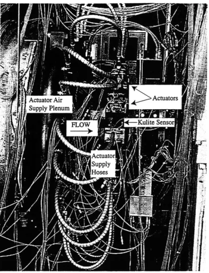
A photograph of the compressor test section is shown in Figure 2-3. One of the unsteady
Kulite pressure transducers is labeled as well as some of the air injection actuators.
2.2
Steady and Unsteady Sensing
Both steady and unsteady measurements were made during the course of this research. The following section discusses the steady measurements from which the compressor speedline and the inputs to the theoretical stall inception model (described in Chapter 3) were
de-termined. Section
useay pressre measuremets usedFigure 2-3: Stage 35 test section.
2.2.1
Steady State Compressor Performance Measurements
NASA Stage 35 is completely instrumented to give detailed, steady state compressor
perfor-mance measurements. The calibration of these steady measurements is regularly updated during compressor operation. All steady state measurements are continuously updated and displayed. Once the compressor pressure and temperature reaches equilibrium at a given operating point, the steady measurements are recorded. Bruckner et al. [6] give a detailed description of the NASA LeRC test facility steady instrumentation.
The sensors which measure the steady pressure and temperature throughout the test section are tabulated in Table 2.3. The standard NASA nomenclature is included to identify the
axial stations. The number and type of sensors are listed as well as the sensor axial2
2
and circumferential3 location. The reported measurement uncertainties are from Reid and
Moore [51].
Table 2.3: NASA Stage 35 steady flow field measurements.
Axial
#
of Sensor Axial Circumferential MeasurementStation Sensors Type Loc. (cm) Angles (deg) Uncertainty
B 4 Wall static pressure -22.48 60, 150, 240, 330 0.03 N/cm2
C 4 Wall static pressure -19.45 60, 150, 240, 330 0.03 N/cm2
CD 2 Hub static pressure -14.81 175, 310 0.03 N/cm2
D 12 Wall static pressure -10.12 15, 45, 75,... 0.03 N/cm2
285, 315, 345
F 4 Wall static pressure -2.16 45, 135, 225, 315 0.03 N/cm2
3 Hub static pressure 4.28 26, 120, 301 0.10 N/cm2
H 5 Casing static pres.1 4.29 79.0, 80.3, 81.6, 0.10 N/cm2
82.9, 84.2
2 Stator leading edge2 4.29 308, 352 0.10 N/cm2
I 4 Wall static pressure 12.23 60, 150, 240, 330 0.10 N/cm2
4 Hub static pressure 25.91 60, 150, 240, 330 0.10 N/cm2
K 4 Wall static pressure 25.91 60, 150, 240, 330 0.10 N/cm2
2 Total pres. rake3 25.91 45, 225 0.17 N/cm2
2 Total temp. rake4 25.91 135, 315 0.6 K
Notes: 1) Casing static pressure measured across 1 stator pitch.
2) Two stator blades instrumented with four total pressure probes at 15,
30, 50, and 85% span along leading edge.
3) 7-element total pressure rakes with probes at 8, 23, 38,
53, 67, 80, and 94% span.
4) 7-element total temperature rakes with probes at 8, 23, 38,
53, 67, 80, and 94% span.
The steady state static pressure at a given axial location is computed by averaging the inner and outer wall static pressure measurements, since the static pressure is fairly uniform radially. The measurements at Station C and CD are used in the upstream duct, Station H in the gap between the rotor and stator, and Station K in the downstream duct. The circumferential average of the steady wall static pressures at Stations B, C, D, F, I, and K are the reference pressures for calibrating the unsteady pressure transducers located at those same axial locations. The total pressure and temperature downstream of the compressor is computed by mass averaging the rake measurements at Station K.
3
The circumferential angles are referenced from the top center of the casing. By convention, an angle is positive in the direction of rotor rotation (the rotor angular velocity vector is directed downstream).


![Figure 3-5: Model of the blade rows in compressible model (modified from [20]).](https://thumb-eu.123doks.com/thumbv2/123doknet/13847143.444507/75.918.182.750.425.745/figure-model-blade-rows-compressible-model-modified.webp)


