HAL Id: cea-02339878
https://hal-cea.archives-ouvertes.fr/cea-02339878
Submitted on 20 Nov 2019HAL is a multi-disciplinary open access archive for the deposit and dissemination of sci-entific research documents, whether they are pub-lished or not. The documents may come from teaching and research institutions in France or abroad, or from public or private research centers.
L’archive ouverte pluridisciplinaire HAL, est destinée au dépôt et à la diffusion de documents scientifiques de niveau recherche, publiés ou non, émanant des établissements d’enseignement et de recherche français ou étrangers, des laboratoires publics ou privés.
Loss of off-site power transient analysis for a
sodium-cooled fast reactor equipped with a gas power
conversion system and preliminary optimisation of its
operation
A. Grange, A. Marrel, J.B. Droin, F. Bertrand, O. Boutin, J.-H. Ferrasse
To cite this version:
A. Grange, A. Marrel, J.B. Droin, F. Bertrand, O. Boutin, et al.. Loss of off-site power transient analysis for a sodium-cooled fast reactor equipped with a gas power conversion system and prelimi-nary optimisation of its operation. Nuclear Engineering and Design, Elsevier, 2018, 355, pp.110315. �10.1016/j.nucengdes.2019.110315�. �cea-02339878�
Loss Of Off-site Power transient analysis for a Sodium-cooled Fast
Reactor equipped with a gas Power Conversion System and
preliminary optimisation of its operation
A. Grange1*, F. Bertrand1,O. Boutin2, JB. Droin1, JH. Ferrasse2, A. Marrel1
1CEA, DEN, DER, SESI, F-13108 Saint-Paul-lez-Durance, France 2Aix-Marseille Université, CNRS, M2P2, F-13451 Marseille, France
* avent.grange@cea.fr
Keywords
Sodium-cooled Fast Reactor (SFR), gas Power Conversion System (PCS), Loss Of Off-site Power (LOOP), Multiobjective Optimisation Problem (MOP).
Abstract
The French Commission for Atomic Energy and Alternative Energy (CEA) in collaboration with its industrial partners develops Sodium-cooled Fast Reactors (SFR) as industrial-scale demonstrators mainly guided by safety and operability objectives. In this paper, a SFR reactor associated to a nitrogen closed Brayton cycle for the Power Conversion System (PCS) is considered. In incidental and accidental conditions, the operation of the reactor must be defined to keep it under control and to fulfil safety requirements. This paper is dedicated to an alternative procedure to control a Loss Of Off-site Power (LOOP). Usually, in case of LOOP, the SFR standard procedure relies on passive Decay Heat Removal (DHR) systems to cool down the primary circuit. In this paper, an alternative solution substitutes the latter by the gas Power Conversion System (PCS). This aims at reducing the delay to reach the cold shutdown state while fulfiling safety criteria dealing with thermal stress issues. The operating of the gas PCS required three regulations:
- The regulation of the Turbo-Machinery (TM) rotation speed to keep a gas flow in the PCS; - The sodium temperature regulation of the secondary circuit, once the cold shutdown state
is reached, to adapt the heat removed by the gas PCS to the decay heat;
- The regulation of the gas temperature at the inlet of the compressors, in the PCS, to keep an efficient heat sink.
The actuator of the sodium temperature regulation of the secondary circuit is chosen among three different actuators thanks to a global sensitivity analysis performed with a metamodel-based methodology. The setting of the controller associated to the TM rotation speed regulation is justified by the study of different proportional-integral-derivative (PID) controllers.
A comparison of this alternative sequence with the reference one, based on simulations with the system thermalhydraulic code CATHARE2, is presented in this paper. The study indicates that the passive DHR systems do not allow the reactor to reach the cold shutdown state after 24 hours, whereas the procedure with the gas PCS required few hours to lead the reactor in this safety state, without increasing thermal stresses on the main vessel. Based on this first result, a Multiobjective Optimisation Problem (MOP) is solved in order to minimize simultaneously the delay to reach the cold shutdown state and the thermal stresses on the main vessel during the alternative procedure. These two objectives are conflicting, thus optimal compromises between them are required to solve the MOP and define a Pareto front. The multiobjective optimization step is supported by the study of different TM rotation speed targets. A Latin hypercube design of experiments is performed with the CATHARE2 code and is used to build the Pareto front. In this way, the alternative procedure allows the reactor to reach the cold shutdown state between 30 minutes and 4 hours. A short delay to reach the safety state induces thermal gradients through
the main vessel about twice higher than the standard procedure, whereas a long delay to reach the safety state can divide the thermal gradients through the main vessel by four. To favour a specific objective of optimisation, this study highlights which TM rotation speed target must be chosen.
Thanks to the regulation of the TM rotation speed, the gas PCS is hence an adaptable system to optimize the thermalhydraulic behaviour of a SFR during a LOOP. Moreover, this alternative procedure strengthens the diversification of the systems to fulfil the DHR function.
1. Introduction
In 2006, the French government decided the commissioning of a new nuclear reactor to contribute to a sustainable management of radioactive material and wastes. This project have to respect the framework developed by the Generation IV International Forum (GIF) (Nuclear Energy Agency, 2016), and hence to participate to the development of the next nuclear energy system generation. In accordance with these decisions, the French Commission for Atomic Energy and Alternative Energy (CEA) in collaboration with its industrial partners investigates the Sodium-cooled Fast Reactor (SFR) technology. In this paper, an industrial-scale SFR with a nitrogen closed Brayton cycle for the Power Conversion System (PCS) is studied to investigate its operability.
For specific incidents and accidents, control procedures must be defined to keep the reactor under control and to fulfil safety requirements. A focus is made on an alternative procedure to deal with a Loss Of Off-site Power (LOOP). Usually, in case of LOOP, SFR rely on specific Decay Heat Removal (DHR) systems to cool down the core. Here, the alternative procedure substitutes specific DHR system by the Nitrogen PCS to remove the decay heat, to reach a cold shutdown state and to maintain this state. The gas PCS requires regulations to operate efficiently the cooling of the reactor. This paper implements efficient statistical methods to define the associated regulations to the alternative procedure and to optimize this one.
After a presentation of the SFR with the Nitrogen PCS option, the modelling of this system with the thermalhydraulic system code CATHARE2 is detailed. Then, the standard procedure with DHR systems and the alternative procedure in case of LOOP accident are described. In the next part, the regulations associated to the alternative procedure are defined using statistical methods. Finally, a comparison of the two procedures is proposed and an optimisation of the alternative procedure is performed to improve the capability of the PCS to cool down the reactor without inducing severe thermal stresses on the main vessel. This optimisation step is supported by an exploration of several turbomachinery (TM) rotation speed targets and a Pareto front is built to select the optimal procedures.
2. Sodium-cooled Fast Reactor design
The aim of this part is to describe the core and the systems of the studied SFR. A focus will be made on the systems used to cool down the reactor in case of LOOP transients.
2.1. Core, primary circuit and secondary circuit
An innovative CFV1 core design for SFR characterized by a low global sodium void worth effect (Chenaud et al., 2013) has been developed by CEA. This concept takes part of the main innovations tested on this kind of reactor. For the CFV core design, the sodium expansion and voiding reactivity feedback increases the margin up to sodium boiling in case of unprotected
1 CFV stands for « Cœur à Faible effet de Vidange » in French that means core with low sodium void worth
transients and reduces the severity of a primary power excursion in case of severe accidents (Bertrand et al., 2016a).
The CFV core thermal power is equal to 1500 MW and all the primary components are included in a main vessel (Figure 1).
A single conical “redan” (inner vessel) separates the primary sodium in two areas: the hot pool, filled with sodium at 550 °C from the cold pool, filled with sodium at 400 °C. Three mechanical Primary Pumps (PPs) are immerged in the primary sodium to ensure the sodium circulation from the cold pool to the hot pool by crossing the core. In steady-state operating conditions, the thermal power is extracted from the primary circuit to the secondary circuit through four Intermediate Heat Exchangers (IHX) (Figure 1).
Figure 1. Primary system arrangement
Control rods located above the core and maintained by electromagnets control the core reactivity. In case of incidental or accidental transient, once a protection threshold is reached, these rods fall by gravity into the core, inducing a reactor scram. After such a scram, the DHR systems remove decay heat to ensure the safety and stability of the reactor.
2.2. Decay Heat Removal systems
One of the main innovations investigated for the SFR is the enhancement of the reliability of the DHR systems, based on a diversification strategy (Hourcade et al., 2016). Three different systems are used to extract the decay heat (Figure 2):
- Two Direct Reactor Auxiliary Cooling Systems (DRACS) named RRB that use air as heat sink. These systems consist in a sodium/sodium heat exchanger located in the hot pool, a sodium circuit and a sodium/air heat exchanger out of the main vessel. The RRB remove the decay heat by natural convection (passive system).
Inner vessel
Core
Main vessel Hot pool
- Two other DRACS named RRA, also using air as heat sink. These systems are composed of a sodium/sodium heat exchanger located in the cold pool, a sodium circuit equipped with a mechanical pump and a sodium/air heat exchanger out of the main vessel.
- Two Reactor Vessel Auxiliary Cooling Systems (RVACS) named RRC, which remove the decay heat directly from the main vessel thanks to radiative heat transfer. These systems are located around the main vessel and are composed of: an oil circuit with a mechanical pump, an oil/water heat exchanger, a water circuit and a water/air heat exchanger with air as heat sink.
Figure 2. Decay Heat Removal systems location
2.3. Secondary circuits
These intermediate circuits remove the heat from the primary circuit and transfer it to the PCS through the IHX and the Sodium Gas Heat Exchangers (SGHE). The secondary side consists in four independent sodium loops, each one being equipped with a mechanical pump. They separate the primary circuit from the PCS in order to reduce the risk of gas inlet in the primary circuit and in the core.
2.4. Power conversion system
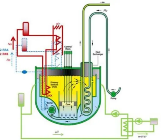
The PCS is a closed Brayton cycle, with two compression stages, in pure nitrogen at 180 bar in the high-pressure line (Figure 3). The plant is composed of two shaft lines with a thermal power of 750 MW each. A turbine, a low-pressure compressor, a high-pressure compressor and a generator are placed on the same shaft line and compose a turbine generator set. For normal operating, the gas temperature is decreased down to 27 °C through the two coolers before each
compressor inlet to limit the compression work. The pre-cooler is located upstream of the low-pressure compressor and the intercooler is located upstream of the high-low-pressure compressor. The heat sink is a water flow through the two coolers. A so-called recuperator Heat Exchanger (HX) allows gas temperature to raise up before its return to the SGHE. The recuperator HX enhances the net efficiency of the power plant that reaches 37.4% with the Gas-PCS.
For regulation and safety issues, by-pass lines equipped of valves are integrated in the Gas-PCS: - The by-pass 1 line (BP1) (red line on the Figure 3) connects the high-pressure compressor
outlet to the pre-cooler inlet. A valve located on this line enables to modify the mechanical balance on the shaft by reducing the gas flow rate through the high-pressure part of the cycle.
- The recuperator by-pass line (orange line on the Figure 3) bypasses the high-pressure side of the recuperator HX by connecting its upstream to its downstream; therefore, the gas which crosses this by-pass line is no more heated up. An opening of the valve located on this line induces a temperature decrease of the gas at the SGHX inlet.
- The SGHX by-pass line: for the gas side of the SGHX (green line on the Figure 3); it connects the upstream of the SGHX to its downstream. An opening of the associated valve decreases the gas flow rate through the SGHX and hence the exchanged power in this HX.
The so-called nitrogen inventory control system called Nitrogen Supply System (NSS) enables to control the nitrogen inventory and consequently to modify the pressure in the PCS. It is composed of a gas extraction line connected to the high-pressure compressor outlet (highest PCS pressure point, blue arrow on the Figure 3) and a gas injection line connected to the pre-cooler inlet (blue arrow on the Figure 3).
Figure 3. Sketch of the SFR with a focus on the Gas-PCS 3. CATHARE2 modelling of the reactor
To study the SFR behaviour in case of a LOOP transient, the whole reactor presented in section 2 is modelled with the thermalhydraulic system code CATHARE2 (Geffraye et al., 2011).
CATHARE2 is a thermalhydraulic system code developed for the last thirty years by the CEA, Electricity of France (EDF), Framatome and the Radioprotection and Nuclear Safety Institute (IRSN). This code, originally devoted to best-estimate transient calculations in pressurized water-cooled reactors, includes six equations (mass, momentum and energy balance for liquid and vapour phases).
The properties of sodium have been implemented, the friction and heat transfer correlations being the same as in the water standard version (Geffraye et al., 2011). In this version of the code, nitrogen gas is considered as an ideal gas.
To compute the neutron power evolution of the core, the following reactivity feedbacks are taken into account: Doppler effect, sodium density, cladding expansion, fuel expansion, hexagonal can expansion, diagrid expansion and finally the reactivity feedback resulting from the relative position of the control rods compared to the core and to the main vessel. All these reactivity coefficients are included in the point kinetics of neutron physics module of CATHARE2 including eight groups of delayed neutrons and four groups of fission products to model the decay heat.
All the computations presented in this article are performed with CATHARE2 v25_3 mod 5.1.
3.2. Input deck content
Primary circuit
The core channels, the IHX, the upstream and downstream of the pumps are modelled as 1-D CATHARE2 axial elements. The flow distribution within the cold and hot pools is modelled thanks to several dedicated 0-D volumes.
Decay Heat Removal systems
Among the three DHR systems, only the RRB are present in the input deck and modelled by a heat sink.
The removed power is considered as a linear function depending of the sodium temperature in the hot pool. This behaviour was observed for reactor tests simulating decay heat removal situations performed in Phenix and Superphenix reactors (Tenchine, 2010). The RRB is designed to extract a thermal power of 50 MW for a sodium temperature in the hot pool of 530 °C and an air temperature of 35 °C. We considered the heat removal as preliminary following the analytical law (1):
𝑄𝐷𝐻𝑅̇ = 50 ∗ 𝑇𝐻−35
530−35 (1)
With:
𝑄𝐷𝐻𝑅̇ : Power extracted by the RRB (MW);
𝑇𝐻: Hot pool temperature (°C).
Power conversion system
The PCS system is fully modelled in the CATHARE2 input deck. Each of the heat exchangers (pre-cooler, intercooler, recuperator) is modelled thanks to two axial elements as a counter flow HX. The water flow in the coolers is modelled thanks to boundary conditions (water-inlet temperature fixed to 21 °C, water-feed flow rate respectively fixed to 12000 kg/s and 9000 kg/s for normal operating conditions in the pre-cooler and the intercooler and the water-outlet pressure fixed to one bar). The rotating mass equation is solved on the shaft including the turbine, the compressors and the resisting torques of the generator when it is connected to the grid. Comprehensive TM performance maps are provided as input data.
The recuperator, the SGHX and the BP1 by-pass lines are modelled thanks to 1-D axial elements and their associated valves can be operated.
- The extraction line is modelled by an orifice, with a diameter of 10 centimetres, a valve and the gas pressure boundary conditions of 1.013 bar;
- In case of a gas removal, the difference between the high-pressure inside the PCS and the atmospheric conditions induces a choked flow. From the conservation equation of the mass, the definitions of the Mach number and of the sound speed, coupled to the isentropic flow relation and the ideal gas equation of state, a compressible form of the mass flow rate is obtained and given by the equation (2).
𝑄𝑐𝑟 = 1 2. 𝜋. 𝐷2 4 . 𝑃𝐶𝐻𝑃. √ 𝑀𝑁2.𝛾 𝑅.𝑇𝐻𝐶𝑃. ( 2 𝛾+1) 𝛾+1 2.(𝛾−1) (2) With: - 𝑄𝑐𝑟: Choked flow (kg/s);
- 𝐷: Diameter of the extraction line section (m);
- 𝑃𝐶𝐻𝑃: Pressure at the outlet of the high-pressure compressor (Pa);
- 𝑀𝑁2: Nitrogen molar mass (g/mol);
- 𝛾: Laplace coefficient (ratio of specific heats, 1.4 for diatomic gas); - 𝑅: Ideal gas constant (J/mol/K);
- 𝑇𝐻𝐶𝑃: Temperature at the outlet of the high-pressure compressor (K).
4. Description of the two LOOP sequences
In case of a LOOP event, a major safety issue is to remove the decay heat of the reactor until the reaching of a stable cold shutdown state (defined by a homogeneous sodium temperature of the primary circuit close to 200 °C). Two procedures are studied in this paper:
- The standard procedure for SFR which relies on the RRB system to remove the decay heat. The Initiating Event (IE) induces a loss of the pumps associated to the RRA and RRC systems, which can not be employed (Tenchine, 2010);
- The alternative procedure, proposed in this paper, substitutes the RRB system by the gas PCS in case of a LOOP. This strategy has preliminary been investigated (Bertrand et al., 2016b). First, it was demonstrated that even if the TM rotation speed decreases to zero (normal behaviour for a LOOP accident), the recuperator HX allows the PCS to conserve a low natural circulation of gas which slows the heating up of the core. Furthermore, in this previous study, it was shown that the operating of the gas PCS can keep running the TM. The forced flow of gas coupled to different back-up flow rates of water in the coolers cools the reactor down. In the present paper, the PCS is also employed to allow the reactor to reach the cold shutdown state, but the TM rotation speed regulation and the water flow rate through the coolers are adapted to this purpose.
In the following, the strategy with RRB and the alternative strategy are described.
4.1. Initiating events and induced effects
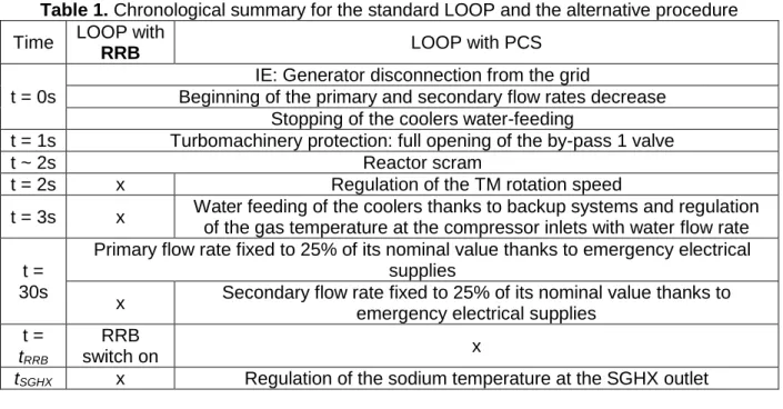
A generator disconnection from the electrical grid initiates the LOOP. The resisting torque in the shaft induced by the generator disappears and involves a turbomachinery overspeed. The detection of the LOOP transient by the control systems causes the full opening of the by-pass 1 valve, which aims at limiting this overspeed. To save the turbomachinery integrity, its rotation speed must not exceed 3300 rpm. In the other part, the LOOP is initiated by the loss of the electrical supplies of the primary and secondary pumps. This loss induces the decrease of the primary and secondary flow rates to 25% of their nominal value in 30 seconds. The water feeding of the coolers is stopped. A few seconds after the IE, the electromagnets maintaining the control rods are switched off and the reactor scram occurs.
4.2. Standard procedure
For this sequence, 30 seconds after the IE, emergency electrical supplies are available to ensure a primary mass flow rate of 25% of its nominal value during the whole transient; however, the secondary pumps are stopped. Then, the RRB system is switched on the excess of the 470 °C sodium temperature threshold at the core inlet, this time is called tRRB. A summary of this standard
procedure is provided in the table 1.
4.3. Alternative procedure
For the alternative sequence, the PCS substitutes the RRB to the decay heat removal. After the IE and the first consequences (cf. section 4.1), several actions are required to keep an efficient heat removal with the water heat sink via the gas PCS and the secondary circuit. As for the standard procedure, 30 seconds after the IE, emergency electrical supplies are available to ensure a primary mass flow rate of 25% of its nominal value during the whole transient. 30 seconds after the IE, the secondary pumps are powered by backup systems and the secondary flow rate is maintained to 25% of its nominal value during the whole transient. The feasibility study and the sizing of the emergency supplies associated to the primary and secondary pumps were realised for the European Fast Reactor (EFR, 1999). Few seconds after the IE, a backup water flow rate is provided as well in the coolers to ensure the heat removal. Furthermore, the water flow rate regulates the gas inlet temperatures of the two compressors to the setpoint of 27 °C, in order to avoid damages on the compressors and keep an efficient heat sink. The power provided by emergency supply limits the maximal water flow rate to 40% of its nominal value.
For this procedure, the PCS is operated in two different ways. First, it cools the reactor down to reach the cold shutdown state and then, it maintains this safe state. In the first step, the gas flow rate must be strong enough to remove the decay heat and the energy previously accumulated in the sodium; once the cold shutdown state is reached, only the decay heat must be removed to maintain the reactor in a safe state. For this purpose, a regulation of the TM rotation speed, by the BP1 valve, ensures a gas flow. The target of this regulation is described by the two parameters:
- A ramp-down period, called tramp, for which the target varies from 3000 rpm to a steady
value;
- The steady value of the rotation speed after the ramp-down period, called ωsteady.
Preliminary results, not mentioned in this paper, have shown that this kind of target for the TM rotation speed, induces a removed power through the SGHX higher than the decay heat. After a delay depending of the ωsteady value, a too much important cooling than needed occurs and could induce a sodium freezing. The selected solution, to adapt the removed power to the decay heat, is to regulate the sodium temperature, at the SGHX outlet, without changing the regulated TM rotation speed. A 180 °C set point is selected to maintain the reactor in the cold shutdown state and the regulation is actuated once the sodium temperature at the outlet of the SGHX becomes lower than 180 °C; the corresponding time is called tSGHX. A summary of this alternative procedure
is provided in table 1. Then, to complete the definition of the alternative sequence, the actuator of the sodium temperature regulation and the controllers associated to each regulation must be defined.
Table 1. Chronological summary for the standard LOOP and the alternative procedure Time LOOP with
RRB LOOP with PCS
t = 0s
IE: Generator disconnection from the grid
Beginning of the primary and secondary flow rates decrease Stopping of the coolers water-feeding
t = 1s Turbomachinery protection: full opening of the by-pass 1 valve
t ~ 2s Reactor scram
t = 2s x Regulation of the TM rotation speed
t = 3s x Water feeding of the coolers thanks to backup systems and regulation of the gas temperature at the compressor inlets with water flow rate t =
30s
Primary flow rate fixed to 25% of its nominal value thanks to emergency electrical supplies
x Secondary flow rate fixed to 25% of its nominal value thanks to emergency electrical supplies
t =
tRRB
RRB
switch on x
tSGHX x Regulation of the sodium temperature at the SGHX outlet
5. Supporting studies for the alternative sequence This part presents:
- The selection of the actuator to regulate the sodium temperature at the SGHX outlet; - The setting of the controller associated to the regulation of the TM rotation speed.
5.1. Sensitivity analysis to select the most influential actuator for regulation
The regulation of the sodium temperature at the SGHX outlet in the alternative sequence can be performed by different actuators available on the gas PCS:
- The valve located on the recuperator by-pass line; an opening of this one induces a temperature decrease of the sodium at the SGHX outlet;
- The valve located on the SGHX by-pass line; an opening of this one induces a temperature increase of the sodium at the SGHX outlet;
- The NSS removal line: a fully opening of the associated valve induces notably a decrease of the gas flow rate through the SGHX and hence a sodium temperature increase at the outlet of the SGHX.
In order to determine the most efficient to achieve the regulation, among these three actuators, a Global Sensitivity Analyses (GSA) is performed with advanced statistical tools. The target criterion (output of the sensitivity analysis) is the amplitude of the temperature variation induced by the three different actions (inputs of the sensitivity analysis). The more a specific action influences the temperature variation, the more the associated actuator is significant to control the sodium temperature.
5.1.1. Metamodel-based methodology for sensitivity analysis
GSA is an invaluable tool to identify the most influential uncertain parameters, their possible significant interactions, and the non-influential parameters (Saltelli, 2002). A widely used GSA approach is the one based on variance decomposition, leading to the definition of Sobol' indices (Sobol, 1993). These sensitivity measures determine how to share the output variance resulting
from each input variable alone (first order Sobol' indices) or from interaction between variables (higher order indices). Higher order indices can also be defined but are not computed in practice. All the Sobol' indices are all included in the interval [0 ; 1], their sum is one in the case of independent input variables and their interpretation is natural: the larger the index value, the more influential the input related to this index. In practice, first order are only computed.
Several statistical Monte-Carlo estimators (Saltelli, 2002, Jansen, 1999) have been proposed to estimate these indices. However, such estimators require several thousand simulations and the loop transient simulated with CATHARE2 is here too time expensive to be directly used to compute efficiently the Sobol’ indices. One solution is then to approximate the CATHARE2 outputs by a CPU inexpensive mathematical function, called surrogate model or metamodel (Fang et al. 2006, Le Gratiet et al. 2017). This metamodel is built from a set of simulations and must be as representative as possible of the simulator in the variation domain of inputs. Among the metamodels classically used in computer experiments, the Gaussian Process (GP) model has shown strong advantages and capabilities (Rasmussen and Williams, 2006 or Marrel et al., 2008). To build this metamodel, a set of code simulations, namely the learning sample, is needed. For this, the use of space-filling designs, which ensure a full coverage of the input space, is recommended. Among classical space-filling designs for computer experiments, we use here optimized Latin Hypercube Samples (LHS, see Fang, 2001 or Damblin et al., 2013 for details). Once the metamodel has been built on the learning sample, its accuracy must be assessed by comparing the observations with the predictions of metamodel, either on an independent test sample or by cross-validation on the learning sample (Hastie et al., 2008). Finally, the validated metamodel is used for GSA by computing Sobol’ indices. The Figure 4 details the methodology.
Figure 4. Metamodel-based methodology for sensitivity analysis
5.1.2. Application and results for the temperature of sodium
The above-described methodology is applied to the variation of the sodium temperature at the outlet of the SGHX, computed by CATHARE2 code, for a transient induced by the simultaneous
using of the three different actuators. These actuators are tested for a nominal power and their explored ranges of variation are summarised in the table 2. Note that these ranges are chosen to be of the same magnitude order as in normal operation.
Table 2. Actuators and associated variation ranges for the sensitivity analysis Actions Lower limit Upper limit Time for which gas is removed with the NSS (s) 0 200
Opening of the recuperator by-pass valve (%) 0 25 Opening of the SGHX by-pass valve (%) 0 25
An optimized LHS2 of N = 600 experiments with three inputs is generated with the R package “DiceDesign” (Dupuy et al., 2005). Each experiment is defined by a set of values for the three above actions; the CATHARE2 code simulates the transient induced by these three simultaneous actions. The CATHARE2 output of interest is the difference between the 345 °C for a nominal power state and the achieved temperature for a new steady state. A GP metamodel is fitted on the learning sample to emulate the output of interest. It has a very high predictivity (99% of output variance correctly predicted by the metamodel). Finally, from the metamodel, Sobol’ indices are computed with the Jansen’s estimator implemented in the R package “Sensitivity” (Pujol G. et al., 2017). The results obtained for first Sobol’ indices are given in table 3. The NSS with a Sobol index of 0.59 (59% of output variance explained) is the most significant actuator. Even if the delay to affect the sodium temperature is higher for the NSS than for the two by-pass valves, its capacities are considered adequate to regulate the sodium temperature.
Note that higher order indices are null (sum of first orders equal to one): this means that there is no significant interactions between the inputs.
Table 3. First Sobol’ indices for the sodium temperature variation at the outlet of SGHX Actuators (Inputs)
Time of gas removal with the
NSS Opening of the recuperator by-pass valve Opening of the SGHX by-pass valve First order Sobol’ indices of
the sodium temperature variation
0.59 0.25 0.16
5.2. Corrector setting for the rotation speed regulation of the turbomachinery
The use of the gas PCS as a DHR system required the following regulations: - The TM rotation speed;
- The sodium temperature at the SGHX outlet; - The gas temperature at the compressor inlets. Their settings are presented in the following.
The control line of the TM rotation speed regulation is designed as the Figure 5.
Figure 5. Control line of the TM rotation speed layout With:
- 𝑒: Difference between the target and the measurement of the TM rotation speed (rpm); - 𝜔: Rotation speed of the TM (rpm);
- 𝜔𝑐: Rotation speed target of the TM (rpm);
- 𝜔𝑚: Rotation speed measurement of the TM (rpm);
- 𝑃𝑈: Opening degree of the BP valve (%);
- 𝑄𝐵𝑃1: Gas mass flow rate through the BP1 line (kg/s).
The output of the PID corrector is: 𝑃𝑈(𝑡) = 𝐾𝑟∗ [𝑒(𝑡) + 1 𝜏𝑖∫ 𝑒(𝑥)𝑑𝑥 𝑡 0 + 𝜏𝑑 𝑑𝑒(𝑡) 𝑑𝑡 ] (3) With: - 𝐾𝑟: Corrector gain (rpm-1);
- 𝜏𝑖: Integral time constant (s);
- 𝜏𝑑: Derivative time constant (s).
Preliminary studies have revealed that the set of values (𝐾𝑟; 𝜏𝑖; 𝜏𝑑) impacts significantly the quality
of the rotation speed regulation. Hence, we fixed this set in order to ensure a high quality for the regulation.
To find a good set of values, we first define pertinent upper and lower bounds of the inputs (given in table 4), according to expert judgement. Then, we explore the domain of variation of these inputs thanks to a space-filling design. For this, an optimized LHS of N = 250 is used (cf. Section 5.1.1). For each set of (𝐾𝑟; 𝜏𝑖; 𝜏𝑑), CATHARE2 code simulates the LOOP accident as defined in
the 4.3 part.
Table 4. Explored ranges to set the PID corrector associated to the BP1 valve
Lower value Upper value
𝐾𝑟 (rpm-1) 9.10-6 9.10-2
𝜏𝑖 (s) 0 3.105
𝜏𝑑 (s) 0 2.104
To assess the quality of each regulations, the difference between the regulated TM rotation speed and its target is considered, via the following Integral Time Square Error (ITSE) criterion:
𝐼𝑇𝑆𝐸 = ∫ 𝑡 ∗ (𝜔(𝑡) − 𝜔𝑡(𝑡)) 2
(𝑡)𝑑𝑡
t5%
With:
- 𝜔(𝑡): TM rotation speed (rpm);
- 𝜔𝑡(𝑡): TM rotation speed target (rpm);
- t5%: Time from which the rotation speed is 5% close of the target (s).
The selected PID corrector is the one that minimizes the ITSE criteria for the 250 experiments, thus defining an efficient regulation:
- 𝐾𝑟𝑜𝑝𝑡 = 1.3.10−3 rpm−1;
- 𝜏𝑖𝑜𝑝𝑡 = 10.7 s; - 𝜏𝑑𝑜𝑝𝑡 = 0.13 s.
The two other regulations used for the alternative procedure preliminary rely on proportional correctors (Table 5).
Table 5. Gain of the proportional correctors used for the standard procedure Regulation Gain of the proportional corrector Temperature of the gas at the inlet of the
compressors 𝐾𝑝𝑐𝑜𝑜𝑙𝑒𝑟𝑠= 160 kg. s
−1. K−1
Temperature of the sodium at the outlet of
the SGHX 𝐾𝑝𝑁𝑆𝑆= 500 kg. °K
−1
The three regulations associated to the gas PCS and the required actions to keep an efficient heat sink and an available secondary circuit are now clearly defined. Hence, the gas PCS could be used to remove the decay heat.
6. Optimisation of the alternative sequence and comparison to the standard sequence In this part, the sequence using the PCS is optimised to find a compromise between fast cooling and low thermal stresses. Then, a comparison of optimal alternative procedures to the standard procedures is performed for the following points:
- Their capability to cool down the reactor;
- Thermal stresses induced on the main vessel during the transient. For the whole following figures, the LOOP IE occurs at 100 seconds.
6.1. Studied variables
The capability of a procedure to cool down the reactor is assessed with the delay to reach the cold shutdown state. In the present study, this time (called 𝑡𝐶𝑆𝐷) is reached when the temperature
of the sodium at the inlet of the core become lower to 210 °C.
Furthermore, the main vessel has to resist to all stresses during its lifetime and avoid creeping conditions. On the one hand, its temperature has to stay below a threshold for which creep is not significant. The main vessel is made of austenitic steel (316L (N)), for this material creeping condition occurred for temperatures higher than 450 °C (Afcen, 2010). A verification of this threshold excess will be made. On the other hand, thermal stresses induced on the main vessel by thermal gradients have to be as low as possible. These stresses are assessed during a transient by the absolute value of the thermal gradient through the main vessel.
With:
𝑔𝑟𝑎𝑑(𝑇) =𝑇𝑖−𝑇𝑜
- 𝑇𝑖: Inside temperature of the vessel (°C);
- 𝑇𝑜: Outside temperature of the vessel (°C);
- 𝑒: main vessel width (4cm).
The thermal gradient is studied at the higher part of the main vessel, where the highest thermal stresses are observed, because of the proximity of the hot pool, which induces a heat-up of the main vessel. Cold sodium flow from the core inlet to an annular space inside and against the main vessel is hence derived to cool down the main vessel. This annular space is called the immersed weir and ensures creep and fatigue resistance of the main vessel. It is at this cooling system that the most significant thermal gradients are observed and in this paper, the two needed temperatures to assess the thermal gradient through the vessel are located at the inlet of the immersed weir. In the following, the maximum absolute value of the thermal gradient is the criterion to assess the thermal stresses induced on the main vessel. We defined it as MTG (°C/cm) (equation 8) depending on the thermal gradient given by the equation 7:
𝑀𝑇𝐺 = max (|grad(T)|) (8)
6.2. Optimisation of the alternative procedure
For the alternative procedure, the definition of the target for the regulation of the TM rotation speed is defined as a solution of the Multiobjective Optimisation Problem (MOP), for which the two variables (𝑡𝐶𝑆𝐷 and 𝑀𝑇𝐺) have to be minimized simultaneously. The inputs of the MOP are the
two descriptive parameters of the TM rotation speed target: 𝑡𝑟𝑎𝑚𝑝 and 𝜔𝑠𝑡𝑒𝑎𝑑𝑦.
The retained problem-solving method is to perform, with the code CATHARE2, several alternative procedures applied for the LOOP accident, for which the TM rotation speed target is modified, and then to select a good candidate to solve the MOP. A LHS (cf. section 5.1.1) including 250 calculations built the database. Its inputs are the two parameters of the TM rotation speed target which variation ranges are set in the Table 6.
Table 6. Variation ranges to the exploration of different TM rotation speed regulation target Lower limit Upper limit
tramp (s) 0 2000
ωsteady (rpm) 1000 2000
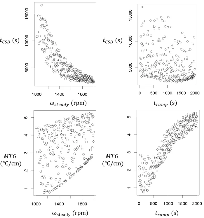
The MOP is characterized by two objectives whose variations are conflicting. On the one hand, the 𝑡𝐶𝑆𝐷 objective decreases significantly with an increase of the 𝜔𝑠𝑡𝑒𝑎𝑑𝑦 parameter. On the other
hand, the MTG increases with an increase of the tramp parameter. These qualitative variations are
observed in the Figure 6, in which each objectives of optimisation of the database are plotted in function of the two descriptive parameters of the TM rotation speed target. However, as shown in the Figure 6, the relation between MTG and 𝜔𝑠𝑡𝑒𝑎𝑑𝑦 and the relation between tCSD and tramp are
not very clear according to this scatterplot analysis. Nevertheless, it can be expected according to engineering judgment that for a high 𝜔𝑠𝑡𝑒𝑎𝑑𝑦 the MTG cannot be minimal because a large TM
rotation speed induces a large PCS flow rate that induces a stronger cooling of the structures. In the same way, a small tramp does not able to have a short tCSD. In this case, the cooling is not
efficient enough because the TM rotation speed and so the gas flow rate are reduced very fast. Finally, to conclude it can be kept in mind that the peak of thermal stress being reached early in the sequence, this value is very impacted by the decrease phase of the TM rotation speed up to its asymptotic value. Conversely, the time to reach the cold shutdown state is largely impacted by the final value of the TM rotation speed because the variable tCSD is about several hours and
therefore is only slightly impacted by the TM rotation speed decrease occurring at the beginning of the sequence.
𝑀𝑇𝐺
(°C/cm)
𝑀𝑇𝐺
(°C/cm)
Figure 6. Scatterplot of the two objectives of optimisation as functions of tramp and ωsteady For this multiobjective conflicting problem, the two objectives have to be minimised simultaneously, it does not exist an unique but several solutions defining the Pareto set for which the two associated objectives (𝑡𝐶𝑆𝐷 and 𝑀𝑇𝐺) define the Pareto front. Each solution of the Pareto
front is an optimum compared to other transients; it means none TM rotation speed target has the property to generate two objectives simultaneously lower than all the members of the Pareto front. Finally, if no preference between the two conflicting objectives is defined, each member of the Pareto front is optimal and do not dominate between themselves.
𝑡
𝐶𝑆𝐷(s)
𝜔
𝑠𝑡𝑒𝑎𝑑𝑦(rpm)
𝑡
𝐶𝑆𝐷(s)
𝑡
𝑟𝑎𝑚𝑝(s)
Based on the LHS above-mentioned, the solution of this MOP is the following Pareto front (Figure 7) associated to the Pareto set (Figure 8) constructed with the R package “rPref” (Roocks, 2016). The Pareto front is included between two extremes (Experiments A and B in the Figure 7), presented in the table 7, which define two large ranges of variation for the two objectives of optimization. The alternative procedure allows the reactor to reach the cold shutdown state between 30 minutes and 4 hours. A short delay to reach the safety state induces a MTG through the main vessel close to 5 °C/cm (“B” experiment), whereas a long delay to reach the safety state induces a MTG through the main vessel close to 1 °C/cm (“A” experiment).
It should be noticed that by considering the set of calculations in a graph representing their input parameters in axis 𝑡𝑟𝑎𝑚𝑝 as a function of 𝜔𝑠𝑡𝑒𝑎𝑑𝑦 a space defined by a 𝑡𝑟𝑎𝑚𝑝 between 500 s and
2000 s and a 𝜔𝑠𝑡𝑒𝑎𝑑𝑦 between 1000 rpm and 1875 rpm (delimitated by a red rectangle in the
Figure 8) is not included in the Pareto set. To solve the MOP, this input space area must not be exploited to define the TM rotation speed target.
Figure 7. Experiments of the database and Pareto front: tCSD=f(MTG)
𝑡𝐶𝑆𝐷 (s) 𝑀𝑇𝐺 (°C/cm) A B Pareto front C Experiments of the LHS
Figure 8. Experiments of the database and Pareto set: 𝒕𝒓𝒂𝒎𝒑 =f(𝝎𝒔𝒕𝒆𝒂𝒅𝒚)
Table 7. Points of interest of the Pareto front
𝑡𝑟𝑎𝑚𝑝 (𝑠) 𝜔𝑠𝑡𝑒𝑎𝑑𝑦 (rpm) 𝑡𝐶𝑆𝐷 (s) 𝑀𝑇𝐺 (°C/cm)
A 145 1141 13915 0.7
B 1340 1903 2157 4.7
C 302 1508 6078 1.4
Thanks to the TM rotation speed target it is possible to choose the objective that has to be minimized. The following part compares the standard procedure to optimised alternative procedure and highlights the relations between the outputs and the inputs.
6.3. Analyse of the optimised alternative procedure and comparison to the standard procedure
The following part provides a comparison of the three optimal procedures defined in the table 7 and the standard procedure. The thermal gradient (Eq. 7) through the main vessel is illustrated for the four compared procedures in the Figure 9. Thermal gradients through the main vessel vary differently for the standard and the alternative procedures. The significant cooling induced by the PCS, leads to an inside temperature of the main vessel lower than its outside temperature. In such situation, the main vessel inside is compressed and the outside is under traction. For the procedure with the RRB the situation is inverted, the main vessel inside is under traction and the outside is compressed. For the RRB procedure the MTG is equal to 3.3 °C/cm.
In spite of these different behaviours, the maximum absolute values of the thermal gradients are of the same order of magnitude for the two procedures. Furthermore, for few optimised alternative procedures, it is possible to reduce these thermal stresses.
𝜔𝑠𝑡𝑒𝑎𝑑𝑦 (rpm)
𝑡𝑟𝑎𝑚𝑝 (s)
Pareto optimal experiments
A
B
C
Figure 9. Thermal gradient through the main vessel
The inlet temperature of the core are plotted for the three procedures defined in the table 7 and for the standard procedure (Figure 10). For the standard procedure, the sodium temperature at the inlet of the core exceeds 450 °C, to reach the temperature threshold of 470 °C which turns on the RRB, and hence induces a significant creep on the main vessel. The passive RRB systems require a delay of 560 seconds to be turned on. Then, 110 seconds after the actuation of the RRB, a decrease of the sodium temperature at the inlet of the core is observed. On the other hand, the procedures with the gas PCS are directly efficient to decrease the sodium temperature at the core inlet. It presents the real advantage to not exceed the threshold of 450 °C and hence to avoid creeping condition.
Furthermore, the passive RRB systems do not allow the reactor to reach the cold shutdown state after a period of 24 hours. For the alternative procedure, the operating of the gas PCS leads the reactor to the cold shutdown state with a delay depending of the TM rotation speed target (Figure 10).
Figure 10. Inlet temperature of the core
The behaviours of the TM rotation speed for the three optimal procedures defined in the table 7 are illustrated in the Figure 11. The experience “A” favours the MTG objective with a low tramp and
a low 𝜔𝑠𝑡𝑒𝑎𝑑𝑦. The experience C keep on favouring the MTG objective with a low 𝑡𝑟𝑎𝑚𝑝 parameter
but a 𝜔𝑠𝑡𝑒𝑎𝑑𝑦 higher than the experience A to improve the second objective 𝑡𝐶𝑆𝐷. Then, the
Figure 11. TM rotation speed associated to the three experiences defined in the table 7 To make a choice through the optimal targets a cobweb plot is a useful tool. This one associated to the Pareto front is built with the R package "plotly" (Carson, 2018) (Figure 12). The Pareto front can be arbitrarily separated in three parts.
- The first part is compounded of elements which favour the MTG: the 𝑡𝐶𝑆𝐷 is higher than
5000 s and the MTG lower than 1.6 °C/cm (green lines in the Figure 12). These transients required a low 𝑡𝑟𝑎𝑚𝑝 combined to an ωsteady inferior to 1600 rpm, in the aim to reduce as
low as possible the 𝑡𝐶𝑆𝐷 without increase too much the MTG. The point A and C of the
table 7 are included in this part.
- The second part is compounded of elements which favour the 𝑡𝐶𝑆𝐷: this one is lower than
3000 s and the MTG higher than 2.8 °C/cm (red lines in the Figure 12). These transients required an 𝜔𝑠𝑡𝑒𝑎𝑑𝑦 superior to 1930 rpm necessarily combined to a 𝑡𝑟𝑎𝑚𝑝 superior to 500
s, to reduce as low as possible the MTG without increasing significantly the 𝑡𝐶𝑆𝐷. The point
B of the figure 7 is included in this part.
- The third part includes optimal compromises for which the 𝑡𝐶𝑆𝐷 value is included between
3000 s and 5000s, and the MTG value is included between 1.6 °C/cm and 2.8 °C/cm (blue lines in the Figure 12). The two first parts can be qualified as compromises privileging one of the two variables of optimisation.
Figure 12. Cobweb plots of the Pareto front
Based on these observations, a privileged objective of optimisation is minimised by selecting a specific domain for the most correlated parameter to this objective. To have a low 𝑡𝐶𝑆𝐷 a high
ωsteady parameter is needed, and to have a low MTG a low 𝑡𝑟𝑎𝑚𝑝 is needed. This result explains
the absence of optimal experiences in the red square of the Figure 8. Then, the second objective can be improved without influencing significantly the privileged objective by adapting the most correlated parameter to this second objective.
To conclude, the alternative procedure by regulating the TM rotation speed improves significantly the thermal hydraulic behaviour of the reactor compared to the standard procedure. Indeed, the cold shutdown state can be reached without increasing thermal stresses. The choice of the two descriptive parameters for the TM rotation speed target must be made in the Pareto set and one objective can be favoured by selecting specific input behaviour for the TM rotation speed target.
𝑡𝑟𝑎𝑚𝑝 (𝑠) 𝜔𝑠𝑡𝑒𝑎𝑑𝑦 (𝑟𝑝𝑚) 𝑡 𝐶𝑆𝐷 (𝑠) 𝑀𝑇𝐺 (°𝐶/𝑐𝑚) 0 0.5k 1.5k 1k 2k
7. Conclusion and prospects
This paper presents an alternative sequence, in case of the LOOP accident, which removes the decay heat with the gas PCS instead of exploiting the RRB system. The three regulations required to operate the cooling of the reactor are:
- The regulation of the TM rotation speed to keep an efficient gas flow;
- The regulation of the sodium temperature at the outlet of the SGHX, to adapt the heat removal to the decay heat, once the cold shutdown state reached;
- The regulation of the gas temperature at the inlet of the compressors, in the PCS, to keep an efficient heat sink.
The choice of the NSS to regulate the sodium temperature at the outlet of the SGHX is supported by Sobol indices calculation. The NSS is the tested actuator that induces the highest variations of this temperature and is hence selected. The setting of the PID corrector associated to the TM rotation speed is performed by a comparison of different settings and the one with the lowest difference between the target and the rotation speed is held.
The alternative procedure in case of the LOOP accident is efficient to reach the cold shutdown state and to maintain it, whereas it is not possible with the RRB for the same scale of time. The PCS, thanks to the regulation of the TM rotation speed with the BP1 valve, is an adaptable system to optimise simultaneously the two conflicting objectives:
- The delay to reach the cold shutdown state; - The thermal stresses on the main vessel.
The Pareto front, associated to this MOP, has been determined and it groups all the optimum compromises. It is up to designers to choose among the Pareto front which transients are the more interesting for them. On the one hand, it is possible to decrease the thermal gradient through the main vessel up to 0.7 °C/cm by accepting the delay to reach the cold shutdown state increases to about 4 hours. On the other hand, it is possible to decrease the delay to reach the cold shutdown state up to about 30 minutes by accepting the thermal gradient through the main vessel increases up to 4.7 °C/cm. With a thermal gradient of 3.3 °C/cm, for the procedure with RRB, it is highlighted that the alternative procedure can reduce the stresses on the main vessel.
Another interesting objective to optimise would be the period for maintaining the reactor in the safe state. The longer this period is the latter the RRB system would be actuated. This possibility is interesting for the probabilistic safety approach by keeping for a long time a diversification of the systems to perform the DHR function.
This study is a first step towards a methodology to optimise the reactor operation in case of various transients. To finalize the methodology, other tools have to be chained to the building of LHS and Pareto front. The latter would be able to define, for a specific transient and a MOP, the procedures to obtain the best compromises.
References
Afcen, 2013; Code of Design and Construction Rules for Mechanical Component in Nuclear Installations (RCC-MRX); Ed. 2012 + 1st addendum December 2013.
Bertrand F. et al., 2016a; Comparison of the behaviour of two core designs for ASTRID in case of severe accidents; Nuclear Engineering and Design, Vol. 297, February 2016, Pages 327-342. Bertrand F. et al., 2016b; Transient behavior of ASTRID with a gas power conversion system; Nuclear Engineering and Design, Vol. 308, August 2016, Pages 20-29.
Carson, 2018; Plotly for R. https://plotly-book.cpsievert.me
Chenaud M.S. et al., 2013; Status of ASTRID core design studies at the end of predesign phase 1; Nuclear Engineering and Technology, Vol. 45, N°6.
Damblin G., Couplet M., Bertrand I, 2013; Numerical studies of space-filling designs: Optimization of Latin Hypercube Samples and subprojection properties. Journal of Simulation. 7. 10.1057/jos.2013.16.
Dupuy D., Helbert C., Franco J., 2015; DiceDesign and DiceEval: Two R Packages for Design and Analysis of Computer Experiments; Journal of Statistical Software, 65(11), 1-38. URL http://www.jstatsoft.org/v65/i11/.
EFR Non Site Specific Safety Report, Framatome/Novatome, 1999
Fang K.-T., 2001; Wrap-around L2-discrepancy of random sampling, Latin hypercube and uniform designs, Journal of Complexity 17, pp 608-624.
Fang K.-T., Li R., Sudjianto A., 2006; Design and modeling for computer experiments, Chapman & Hall/CRC.
Geffraye G. et al., 2011. CATHARE 2 V2.5_2: A single version for various applications, Nuclear Engineering and Design, Vol. 241, Issue N°11, November 2011, Pages 4456-4463.
Hastie T. J., Tibshirani R. J., Friedman J. H., 2008; The Elements of Statistical Learning: Data Mining, Inference, and Prediction, Springer series in statistics, 2nd edn, Springer, New-York. Hourcade E. et al., 2016. ASTRID Nuclear Island design: advances in French-Japanese joint team development of Decay Heat Removal systems, Proceedings of ICAPP, San Francisco, USA, April 17-20, 2016
Jansen M.J.W., 1999, Analysis of variance designs for model output. Computer Physics Communication, 117, Pages 35–43
Le Gratiet L., Marelli S., Sudret B., 2017; Metamodel-Based Sensitivity Analysis: Polynomial Chaos Expansions and Gaussian Processes. In: Ghanem R., Higdon D., Owhadi H. (eds) Handbook of Uncertainty Quantification. Springer, Cham
Marrel A., Iooss B., Van Dorpe F., Volkova E., 2008; An efficient methodology for modeling complex computer codes with Gaussian processes; Computational Statistics and Data Analysis, Elsevier, 2008, 52, pp.4731-4744.
Nuclear Energy Agency. 2016. GIF Annual report. 2016.
Pujol G., Iooss B., Janon A. et al., 2017. Sensitivity: Global Sensitivity Analysis of Model Outputs. R package version 1.15.0. https://CRAN.R-project.org/package=sensitivity
Rasmussen C., Williams C., 2006; Gaussian processes for machine learning, MIT Press.
Roocks Patrick. 2016. rPref: Database Preferences and Skyline Computation. R package version 1.2. https://CRAN.R-project.org/package=rPref
Rob Carnell. 2018. lhs: Latin Hypercube Samples. R package version 0.16. https://CRAN.R-project.org/package=lhs
Saltelli A., 2002. Sensitivity analysis for importance assessment, Risk Analysis 22 (2002) 1-12. Sobol I.M.,1993. Sensitivity analysis for non-linear mathematical models. Mathematical Modeling & Computational Experiment (Engl. Transl.), 1, Pages 407–414.
Tenchine D., 2010. Some thermal hydraulic challenges in sodium cooled fast reactors, Nuclear Engineering and Design, Vol. 240, Issue N°5, May 2010, Pages 1195-1217.
Nomenclature
D Diameter of the NSS extraction line section (m)
𝑒 Difference between the target and the measurement of the TM rotation speed (rpm)
𝛾 Laplace coefficient
𝐾𝑟 Corrector gain (rpm-1)
𝑚𝑁2 Nitrogen mass in the PCS (kg)
𝑀𝑁2 Nitrogen molar mass (g/mol)
MTG Maximum absolute value of the thermal gradient through the main vessel (°C/cm)
𝜔 Rotation speed of the TM (rpm)
𝜔𝑚 Rotation speed measurement of the TM (rpm)
ωsteady Steady value of the TM rotation speed target (rpm)
𝑃𝐻𝐶𝑃 Pressure at the outlet of the high-pressure compressor (Pa)
𝑃𝑈 Open degree of the BP valve (%)
𝑄𝑤𝑎𝑡𝑒𝑟 Water flow rate through the coolers (kg/s)
𝑄𝐵𝑃1 Gas flow rate through the BP1 line (kg/s)
𝑄𝑐𝑟 Choked flow (kg/s)
𝑄𝐷𝐻𝑅̇ Power removed by the RRB (MW)
𝑅 Ideal gas constant (J/mol/K)
t Time (s)
tCSD Delay to reach the cold shutdown state of the reactor since the initiating
event of the LOOP (s)
𝑡𝑟𝑎𝑚𝑝 Ramp-down period, during which the TM rotation speed target varies
from 3000 rpm to a steady value (s)
tRRB Time for which the RRB are switched on (s)
tSGHX Time for which the regulation of the sodium temperature at the outlet of
the SGHX is actuated (s)
𝑡5% Time from which the speed rotation is 5% close of the target (s)
𝑇𝐻 Hot pool sodium temperature (°C).
𝑇𝐻𝐶𝑃 Temperature at the outlet of the high-pressure compressor (K)
𝑇𝑖 Vessel inside temperature (°C)
𝑇𝑖𝐶𝑃 Gas temperature at the inlet of the compressors (°C) 𝑇𝑜 Vessel outside temperature (°C)
𝑇𝑜𝑆𝐺𝐻𝑋 Temperature of the sodium at the outlet of the SGHX (°C) 𝜏𝑑 Derivative time constant (s).
𝜏𝑖 Integral time constant (s) Subscripts
opt Related to the optimal PID corrector selected to regulate the rotation speed of the TM
Glossary
BP1 Specific By-Pass line interlinking the high-pressure compressor outlet to the pre-cooler inlet
CFV core Low void worth core
DHR Decay Heat Removal
DRACS Direct Reactor Auxiliary Cooling System
EFR European Fast Reactor
GIF Generation IV International Forum
GP Gaussian Process
IE Initiating Event
(I)HX (Intermediate) Heat Exchangers ITSE Integral Time Square Error criteria LHS Latin Hypercube Sampling
LOOP Loss Of Off-site Power
MOP Multiobjective Optimisation Problem NSS Nitrogen Supply System
PCS Power Conversion System
PID Proportional-Integral-Derivative
PP Primary Pump
RRA Active DHR systems with a heat exchanger in the cold pool RRB Passive DHR systems with a heat exchanger in the hot pool RRC DHR systems using radiation through the main vessel RVACS Reactor Vessel Auxiliary Cooling System
SA Subassembly
SGHE Sodium Gas Heat Exchangers SFR Sodium-cooled Fast Reactor