4D Printing: Towards Biomimetic
Additive Manufacturing
Elizabeth Yinling Tsai
B.S. as recommended by the Department of Materials Science & Engineering
& in Engineering as recommended by the Department of Mechanical Engineering
Massachusetts Institute of Technology (2011)
Submitted to the Program in Media Arts and Sciences, School of Architecture and Planning, in partial fulfillment of the requirements for the degree of
Master of Science in Media Arts & Sciences I MASSACHUSETTS INGE1
OF TECHNOLOGY
at the
JUL 14
2014
Massachusetts Institute of TechnologySeptember 2013 LIBRARIES
Massachusetts Institute of Technology 2012. All rights reserved.
Author:
Signature redacted
Elizabeth Yinling Tsai Programi Media Ar sand Sciences
/ugust 9, 2013
Certified by:
Signature
redacted,-Prof. Neri Oxman Assistant Professor o Media Art and Sciences
Program i edia Arts and Sciences Thesis Advisor
Signature redacted
Accepted by:
Prof. Patricia Maes Associate Academic Head Program in Media Arts and Sciences
4D Printing: Towards Biomimetic
Additive Manufacturing
Elizabeth Yinling Tsai
Submitted to the Program in Media Arts and Sciences, School of Architecture and Planning, on August 9, 2013 in partial fulfillment of the requirements for the degree
of Master of Science in Media Arts & Science at the Massachusetts Institute of Technology
Abstract
Inherent across all scales in Nature's material systems are multiple design dimensions, the existences of which are products of both evolution and
environment. In human manufacturing where design must be preconceived and deliberate, static artifacts with no variation of function across directions, distances or time fail to capture many of these dimensions. Inspired by Nature's ability to generate complex structures and responses to external constraints through
adaptation, "4D printing" addresses additive fabrication of artifacts with one or more additional design dimension, such as material variation over distance or direction and response or adaptation over time. This work presents and evaluates a series of enabling explorations into the material, time and information dimensions of
additive manufacturing: a variable elasticity rapid prototyping platform and an approach towards Digital Anisotropy, a variable impedance prosthetic socket (VTS) as a case study of interfaces between nature and manufacture, CNSilk as an example of on-demand material generation in freeform tensile fabrication, and Material DNA as an exploration into embedded spatio-temporal content variation.
This work was supported in part by NSF EAGER grant award #1152550 "Bio-Beams: Functionally Graded Rapid Design & Fabrication", VA contract # VA118-12-C-0040, and the Media Lab Consortium.
Thesis Advisor: Dr. Neri Oxman
Title: Assistant Professor of Media Arts and Sciences, Program in Media Arts and Sciences
4D Printing: Towards Biomimetic
Additive Manufacturing
Elizabeth Yinling Tsai
Submitted to the Program in Media Arts and Sciences, School of Architecture and Planning, in partial fulfillment of the requirements for the degree of
Master of Science in Media Arts & Science
Signature redacted
Thesis Reader:
Hugh Herr Associate Professor of Media Arts and Sciences Program in Media Arts and Sciences
4D Printing: Towards Biomimetic
Additive Manufacturing
Elizabeth Yinling Tsai
Submitted to the Program in Media Arts and Sciences, School of Architecture and Planning, in partial fulfillment of the requirements for the degree of
Master of Science in Media Arts & Science
Signature redacted
Thesis Reader:
Edward Boyden Associate Professor of Media Arts and Sciences Program in Media Arts and Sciences
Acknowledgements
My past six years at MIT, and in particular the most recent two at the Media Lab,
have played an major role in making me who I am as an individual, researcher and engineer. There have been countless individuals who have contributed deeply to this journey of learning and personal growth - certainly more than I have been able to mention here. To all of you, I would like to say thank you with the utmost
sincerity. Nothing would have been possible without each of you.
Neri Oxman, my advisor, for giving me a chance and for being an incredibly open
and encouraging mentor. Thank you for continuously pushing me to see and think about the world in new ways.
My thesis readers, Hugh Herr and Ed Boyden for their input and discourse. Thank
you for taking the time.
The Mediated Matter group: Steven Keating, Ben Peters, Michal Firstenberg,
Yoav Sterman, Carlos Gonzales, Markus Keyser and Jared Laucks for being
invaluable team mates and colleagues as well as Zjenja Doubrovski and Federico
Mazzolini for the many engaging discussions and insights.
Phil Salesses, my best friend, above all for believing in me and always being there.
The people who make what we do possible: Sarah Ryan who has been more amazing than we thought possible, Cynthia Wilkes for being so willing to aid and assist, and the indefatigable Linda Peterson for putting up with all of us year after year. Tom Lutz and John Difrancesco in the shop for being so patient and capable.
Stratasys and Daniel Dikovsky who made the translation from concept to reality
Arthur Petron and David Sengeh from the Biomechatronics Group for the
invaluable discussions, input and advice.
My wonderful UROPs, in particular Ben Lehnert, who remind me how little I know
and motivate me to always continue to learn.
My former UROP mentor, Nate Reticker-Flynn. You exemplify a degree of
dedication to mentoring and research that I will only ever aspire to. Prof.
Sang-Gook Kim for revealing to me a first glimpse of the world of research and Prof. Yoel Fink for taking the time to care and offer words of wisdom.
And then, most certainly, my parents, Rose Lee and Eric Tsai, as well as my brother,
Enoch, for helping me get here in the first place and for their unquestionable love
Table of Contents
1. INTRODUCTION & BACKGROUND... 10
1.1 MOTIVATION & LIMITATIONS OF CURRENT ADDITIVE MANUFACTURING ... 10
1.2 4D PRINTING: TOWARDS BIOMIMETIC ADDITIVE MANUFACTURING ... 10
1.3 STATE OF THE A RT IN 3D PRINTING ... 11
1.4 4D EXAM PLES IN CURRENT M ANUFACTURING... 12
1.5 THESIS O RGANIZATION... 13
2. A PPR O A CH & M ET H O D O LO GY ... 15
2.1 M ETHODOLOGY...15
2.2 NATURE'S WAY: BIOLOGICAL PARALLELS FOR ADDITIVE MANUFACTURING...15
2.2.1 Aggregate System s ... 16
2.2.2 Tensile W eb and M em brane System s... 17
2.2.3 Cellular Com pressive System s... 19
2.2.4 Cellular Tensile System s... 19
2.3 D EFINING THE 4TH DIMENSION ... 20
2.3.1 In N ature... 20
2.3.2 In Layered M anufacturing ... 20
2.3.2.1 The M aterial Dim ension...20
2.3.2.2 The Tim e Dim ension...22
2.3.2.3 The Inform ation Dim ension ... 22
2.4 INTERFACING BETWEEN NATURE AND ADDITIVE MANUFACTURING... 23
3. IM PLEM EN TA T IO N ... 25
3.1 OVERVIEW ... 25
3.2 THE M ATERIAL D IMENSION: DIRECTION & D ISTANCE ... 25
3.2.1 Vision: Adaptation of Composition & Form... 25
3.2.2 Digital Anisotropy: A Variable Elasticity Rapid Prototyping Platform...26
3.2.2.1 M otivation ... 26
3.2.2.2 Design and Control ... 27
3.2.2.3 Gradient Fabrication...31
3.2.3 Physical Interfaces: Variable Impedance Test Socket... 34
3.2.3.1 M otivation & Background...34
3.2.3.2 Process Overview ... 36
3.2.3.3 Data Collection...38
3.2.3.4 M odeling...42
3.2.3.5 M aterial M apping ... 45
3.2.3.6 Shape Determ ination...46
3.2.3.7 File Generation...47
3.2.3.8 Socket Fabrication ... 50
3.3 THE TIM E DIM ENSION: GROW TH AND RESPONSE ... 53
3.3.1 Vision: Fabrication Material Behavior & Response ... 53
3.3.2 On-demand Material Generation: ... 53
3.3.2.1 Overview & M otivation...54
3.3.2.2 Design...55
3.3.2.3 M aterial Generation: Nylon 6,6... 56
3.3.2.4 Discussion & Realization...59
3.3.3 Environmental Response: Passive Smart Glass... 60
3.4.1 Vision: M aterials As Software... 62
3.4.2 Em bedding Inform ation: Material DNA ... 62
4. EVALUATION & CONTRIBUTIONS... 65
4.1 THEORY & METHODOLOGY: EXPLORATION OF ADDITIONAL FABRICATION DIMENSIONS.... 65
4.1.1 Nature: Growth, Adaptation, Evolution ... 65
4.1.2 M anufacture: Defining The 4th Dim ension... 65
4.2 TECHNOLOGY ... 65
4.2.1 Object Representation: Bitm ap Printing ... 65
4.2.2 Platform s: CNSilk and Variable Elasticity Printer... 66
4.2.3 System s: M aterial DNA ... 66
4.3 IMPLICATIONS IN DESIGN AND FABRICATION ... 66
5. CONCLUSIONS... 68
List of Figures
FIGURE 1. ADAPTATION OF COMPOSITION AND FORM IN NA TURE'S MATERIAL SYSTEMS... 16
FIGURE 2. ENVIRONMENTAL SCANNING ELECTRON MICROGRAPHS OFSPIDER SILK FIBERS). ... 18
FIGURE 3. COMPOSITE IMAGE OF CARPAL SKIN . ... 21
FIGURE 4. VARIABLE ELASTICITY PRINTING PLATFORM ... 27
FIGURE 5. VARIA BLE ELASTICITY PRINTING PLATFORM: TOP viEw ... 28
FIGURE 6. VARIABLE ELASTICITY PRINTING PLATFORM: SOLENOID VALVES AND MA TERIAL RESERVOIRS ... 29
FIGURE 7. VARIABLE ELASTICITY PRIN TING PLATFORM: PASSIVE MIXER ... 29
FIGURE 8. VARIABLE ELASTICITY PRINTING PLATFORM: COLOR GRADIENTS ... 32
FIGURE 9. VARIABLE ELASTICITY PRINTING PLATFORM: CAST SILICONE SHEET . ... 32
FIGU RE 10. VARIABLE ELASTICITY PRINTING PLATFORM: UV CURE SILICONE AND POLYURETHANE SAMPLES TESTED...33
F IGU RE 11. VA RIABL E ELASTICI TY PRINTING PLA TFORM: TWO-DIMENSIONAL GRADIENTS ... 34
FIGURE 12. VTS: DESIGN AND FABRICA TION PROCESS ... ... 37
FIGURE 13. VTS: IMAGES FROM MRI SCAN OFA RIGHT RESIDUAL LIMB ... 39
FIGURE 14. VTS: TISSUE DISPLACEMENT VS TISSUE THICKNESS. ... 40
FIGURE 15. VTS: STIFFNESS VS TISSUE THICKNESS ... 41
FIGURE 16. VTS: ORIGIN AND AXIS FOR DATA STRUCTURE . ... ... ... 42
FIGURE 17. VTS: RENDERINGS . ... 46
FIGURE 18. VTS: DETERMINING SOCKET SHAPE ... 47
FIGURE 19. VTS: BITMAP FILES ... 50
FIGURE 2 .0. VTS: PRINTED SOCKET ... 51
FIGURE 21. VTS: COMPOSITE SHELL DESIGN...52
FIGURE 2 2. VTS: COMPOSITE SHELL LA YUP... 52
FIGURE 23. CNSILK: KUKA ATTACHMENT ... 56
FIGURE 24. CNSILK: NYLON 6,6 SYNTHESIS... 57
FIGURE 25. CNSILK: ROBOTICARM WEAVING ... 58
FIGURE 26. CNSILK: NYLON 6,6 MEMBRANES ... 59
FIGURE 27. PASSIVE SMART GLASS EXAMPLE ... 61
1. Introduction & Background
1.1 Motivation & Limitations of Current Additive Manufacturing
State of the art additive-manufacturing platforms typically utilize a wide variety of materials and combinations of materials to 3D print objects with complex geometries. Typically necessitated by the fabrication process itself, such objects are fabricated in a layer-by-layer method (Levy, Schindel, & Kruth, 2003). Although some work has been done towards heterogeneous object modeling in layered manufacturing (Patil, Dutta, Bhatt, Jurrens, Lyons, & Pratt, 2002), variations in bulk material properties or anisotropies of the object are often byproducts of the
fabrication itself (Ahn, Montero, Odell, Roundy, & Wright, 2002) (Cooke, Tomlinson, Burguete, Johns, & Vanard, 2011).
Currently, the most accessible approaches to the fabrication of designed anisotropy are achieved through the introduction of spatial non-uniformity in
material composition (Oxman, Keating, & Tsai, 2011). Tangible examples include the optimization of cellular material distributions and density in response to loading patterns on the architectural scale as well as geometrical and material gradients of varying elasticity on product scale applications (Oxman, Tsai, & Firstenberg, 2012). Such efforts enable the user to design, control and modulate properties across spatial and temporal scales, designing both material and organization.
1.2 4D Printing: Towards Biomimetic Additive Manufacturing
In moving towards the nexus of biomimetic fabrication and additive
manufacturing, several limitations arise in prototyping with current methods and materials. Static objects with no functional variation across directions, distances or time fail to capture many of the intricacies inherent across different scales in Nature's designs. As concrete examples: orthoses and prostheses intended to interface intimately with the human form embody intricate geometries yet are typically composed of a number of homogenous materials. Given that the shape and
volume of human limbs fluctuate during each step and throughout different levels of activity due in part to muscle contractions and other forces there is real need for artifacts that are able to comfortably accommodate this broad range of movements.
This thesis introduces the term "4D printing" addresses the rapid fabrication of artifacts with one or more additional design dimensions. In particular, 4D
printing is defined as the fabrication of objects through the deposition of a material using a print head, nozzle, or other printer technology where the objects contain one or more additional design dimension, such as material gradation over distance or direction, response or adaptation over time, or controlled anisotropy throughout volume.
1.3 State of the Art in 3D Printing
Additive and layered manufacturing systems allow for objects of varying complexity to be serially produced in a one-off fashion from 3D model data. Using a single manufacturing system, a large number of unique objects may be fabricated without additional molds or tooling, though support materials may sometimes be used (Weiss, et al., 1997). Examples of layered manufacturing include fused
deposition modeling (FDM), selective laser sintering (SLS), stereolithography (SLA), laminated object manufacturing (LOM), and 3D printing. Each method is typically limited in the materials that it may fabricate with depending on the Nature of the process and post-processing steps. An FDM printer, for example, may print with thermoplastic materials as well as a water- soluble material, the latter of which is later removed. With the exception of Stratasys' simultaneous multi-material jetting technology commercial methods are limited in the range of achievable material properties and are generally unable to combine different materials within a single printed model.
Advances in commercial additive manufacturing technologies often occur in one of two directions: increased resolution or material developments. FDM methods developed by Stratasys, for example, extrude thermoplastic materials while multiple
material photolithography platforms such as the Objet500 Connex Multi-Material Printer are able to duplicate a wide range of material properties such as stiffness, tensile strength, durometer, opacity and color using its Digital Materials (Stratasys). Methods such as electron beam melting and direct metal laser sintering can work with metal materials while other SLS machines can print with wider ranges of commercially available powder materials ranging from plastics to ceramics and glass. Technologies developed more recently in research stages work with biological materials and scaffolds as they seek to expand from the nanoscale to the
architectural scale (Buswell, Soar, Gibb, & Thorpe, 2007) (Melchels, Feijen, & Grijpma, 2010).
1.4 4D Examples in Current Manufacturing
With current additive manufacturing methods, there has been some
exploration of material property and response modulation as functions of direction, distance, and time. Instances of this may be seen in materials with specifically manufactured anisotropic properties, passive responsive materials, and graded material distributions. Concepts of 4D printing are embodied in examples of functionally graded rapid prototyping (FGRP) and variable property rapid prototyping (VPRP) for example (Miyamoto, Kaysser, Rabin, Kawasaki, & Ford,
1999) (Weiss, et al., 1997) (Oxman, 2010). In both FGRP and VPRP, the assignment
of material properties and distribution are modulated as a function of either distance or direction. By enabling the design of functional structural components through the controlled spatial variation of material properties in continuous gradients, they result in structures highly optimized to fit environmental
performance requirements (Oxman, 2011) (Oxman, Keating, & Tsai, 2011). Digital Anisotropy then allows for the control of both density and directionality of material substance as well as property across multiple scales and locations.
Beyond material variations, other examples focus on event-specific interactions with the environment post-fabrication. Work on printed origami
explores structure periodicity and the transition between dimensionality, where multiple structures can be created from a single printed lattice design through different folding pathways (Ahn, Montero, Odell, Roundy, & Wright, 2002). Certain multivascular self-healing materials respond to crack-induced rupture of embedded capsules - and hence the material itself - with automatic repair (Toohey, Sottos, Lewis, Moore, & White, 2007).
In a more deliberate sense, structures and devices may be fabricated with specific dynamic functions, as with electrically small 3D antennas (Adams, et al., 2011). Using conventionally fabricated shape changing materials such as shape memory alloys and polymers assembled with 3D printed parts, smart actuators, structures, and mechanisms may be produced (Walters & Rossiter, 2008) with applications in soft robotics (Rossiter, Walters, & Stoimenov, 2009) and art and design (Walters & McGoran, 2011). Most recently, the rapid prototyping of artifacts designed to self-assemble or undergo specific transformations post-fabrication has emerged (Tibbits, 2013). With such smart structures, external stimuli function not only as a trigger event but also provide the energy necessary for actuation.
1.5 Thesis Organization
This thesis is composed of five chapters. Chapter 1: Introduction &
Background discusses the limitations of current additive manufacturing, introduces the concept of 4D printing, and examines the state of the art in 3D printing. Chapter 2: Approach & Methodology describes the systematic method used in the exploration
of 4D printing and presents a series of biological parallels for additive
manufacturing present in Nature. It seeks to define the 4th dimension in both nature and layered manufacturing as well as the interfaces between such. Chapter 3:
Implementation presents in detail a number of case studies towards enabling 4D printing categorized into the material, time and information dimensions. Two case studies are considered under the material dimension: a variable elasticity rapid prototyping platform and an approach for fabricating variable impedance test
sockets. Towards the time dimension, CNSilk is explored as an on-demand material generation platform. Lastly, Material DNA is discussed as an approach towards linking and embedding information within physical objects. Chapter 4: Evaluation & Contributions evaluates the theoretical, methodological and technological
contributions of the thesis and Chapter 5: Conclusions sums up the work presented and expounds on the future of 4D printing.
2. Approach & Methodology
2.1 MethodologyMuch of the inspiration for this research direction stemmed from initial exploration and examination of biological case studies followed by technology surveys to identify key limitations of biomimetic fabrication and rapid prototyping. The work presented in this thesis includes explorations into variable density
fabrication (Oxman, Keating, & Tsai, 2011), freeform and tensile member fabrication (Tsai, Firstenberg, Laucks, Sterman, Lehnert, & Oxman, 2012) and digital anisotropy (Oxman, Tsai, & Firstenberg, 2012). The research followed an Analysis-Synthesis-Analysis model where different material systems were first analyzed through imaging as well as chemical and mechanical modeling. Key fabrication
characteristics were then incorporated into new processes using both existing and custom-built robotic systems such as the KUKA KR5 sixx R850 industrial 6-axis robotic arm and evaluated. The case studies developed sought to touch on each of the three main categories of the 4t dimension, identified as Material, Time and Information.
2.2 Nature's Way: Biological Parallels for Additive Manufacturing
In Nature, there are numerous case examples of layered construction in material systems across all scales. Unlike machine layered manufacturing systems which typically operate in Cartesian coordinates with material deposition on one plane (e.g. x- y) and layers advancing in the direction of a single axis (e.g. z), Nature employs a much more organic process. The structures that result are products of evolution, which exemplify not only functional design but also principles of the underlying behavior and organization of the process itself (Figure 1). Additionally, in Nature, not only do living material systems adapt and fabricate as a result of the environment that they operate in, there is often a propagation of design and information onto other organisms and future generations. Following, we offer a classification of Nature's material systems based on the extent to which they adapt
to environmental conditions and constraints through the modulation of material composition or evolution of form.
CA
0
O Cellular Tensile Systems 0.
E 0
Cellular Compressive Systems
o
00.U Tensile and Web Systems
S Aggregate Systems
Adaptation of Form Figure 1. Adaptation of composition and form in Nature's material systems. The
material generation process determines, in a way, the extent to which material composition and form may be adapted as a response to environmental conditions and constraints. With aggregate systems such as nests, birds craft with what is readily available in their environment. In cellular compressive systems, e.g. trabecular bone, the density, composition, and hence material properties adapt continuously in response to loading histories.
2.2.1 Aggregate Systems
In aggregate systems, Nature adapts the material system, taking what is available and shaping it according to environmental factors. Many bird species in Nature construct nests of varying complexity through the sculpting, molding, piling, interlocking or weaving of different organic and inorganic materials. The nests designs are, to some extent, inherent to the birds themselves (as different species behave in distinctive manners) but they are also the result of an evolving algorithm
dependent on the properties of the available and chosen materials (Hansell, 2000). The fabrication process shapes the materials as the materials shape the process.
In some ways, complex multifunctional nests speak to the cumulative power of simple design processes and building algorithms. Plain-fronted thornbirds, for example, establish the initial platform for their nests through a long process of carrying sticks to a chosen intersection. Most of these sticks fall until an
arrangement is achieved that is sufficient to withstand the wind overnight. The finished nest is a well-designed aggregate of different sticks, grasses, leaves, and other materials gathered from the environment with material distributions informed by function (Thomas, 1983).
2.2.2 Tensile Web and Membrane Systems
In many of Nature's tensile and membrane systems, the material itself is modulated to environmental factors as well as function. Spiders are one of many animals that produce spun fibrous secretions known as silk, which can be arranged into web and membrane structures. Aranaeid spiders, which weave orb-webs, use upwards of seven different types of silks to accomplish different functions (Gosline, Demont, & Denny, 1986). These silks are optimized for a wide range of different conditions, including but not limited to mechanical properties such as strength and toughness. Not only are there different types of silks, but the silks themselves may be rapidly adapted to different parameters during the silk spinning process. The final webs take into account a delicate balance of function, environmental conditions and material efficiency as limited by the energy resources of the spider (Vollrath,
Figure 2. Environmental scanning electron micrographs ofspider silkfibers
illustrating the different structures present including differentfiber widths (top - scale bar 100um) and droplets ofglue (bottom right - scale bar 1Oum). Image of cross-section of Bombyx mori silkworm cocoon demonstrating fibrous anisotropy and layered construction (bottom left - scale bar 1 00um).
The complexity of web systems is further evident in micro and
nanostructures observed in silk (Figure 2). They are designed not only to respond to immediate factors such as wind, temperature and artifacts, but also to anticipate and predict future events. 3D webs, such as those spun by black widow spiders, are composed of a large number of silk fibers designed to break when struck in order to dissipate the energy required to trap an insect. However, in 2D webs such as orb-webs, the capture threads must not break and hence energy is dissipated through stretching. The molecular structure of these capture threads can be seen as molecular nanosprings, which contribute to its elasticity (Becker, et al., 2003).
2.2.3 Cellular Compressive Systems
In cellular compressive materials systems that develop within living organisms such as bone and wood, a more continuous evolution is evident as
loading histories and stresses affect both fabrication and renewal. The structure and density of bone is known to vary depending on the loading conditions that it is subject to (Carter, Fyhrie, & Whalen, 1987). This form is not static, but rather its maintenance and adaptation depends on mechanical forces and loading histories. Bone can be classified as two main types, compact and cancellous, depending on its relative density, with compact bone containing a volume fraction of solids over 70% and cancellous bone under 70%. Cancellous bone is a cellular material that can develop different structures depending on its relative density. At low densities, it forms open cells with rod-like elements; at higher densities, it forms closed-cell structures. These structures are formed as either asymmetric or columnar depending on loading conditions and directions (Gibson, 1985).
The extent of mechanical loading that bones are exposed to is related to the mass and strength of the bones with heavier and stronger bones often observed in heavier individuals (Carter, Fyhrie, & Whalen, 1987). In homeostasis, bone
resorption by osteoclasts and bone formation by osteoblasts are equal in rate and hence bone mass and architecture are unaffected. Increased strain in the bone through strenuous exercise for example, may lead to additional bone formation until the new strains are normalized (Huiskes, Ruimerman, van Lenthe, & Janssen, 2000).
2.2.4 Cellular Tensile Systems
Human skin comprises a cellular tensile system with variations in elasticity, stiffness and thickness depending on age, location and function. There is an
intelligent predetermination of cellular structure and tensile properties as well as a gradual evolution based on external forces and stresses. Skin tends to be thicker on lower parts of the face compared with upper parts for example (Pellacani &
Seidenari, 1999) (Malm, Samman, & Serup, 1995). There's an observed decrease in elasticity with age and increase in thickness in certain locations. These properties
are controlled in part by the microarchitecture of the connective skin tissue and its ability to deform under stress. Modification and impairment of this architecture can lead to improper decreases in elasticity as seen in some pathological skin conditions (Pierard & Lapiere, 1977).
2.3 Defining the 4th Dimension
2.3.1 In Nature
Inherent in Nature's material systems are multiple design dimensions, the existences of which are products of both evolution and environmental conditions. These dimensions can be seen as functions of direction, distance or time depending on how they are modulated. Anisotropy in wood grains and animal tissues are often present as functions of direction while material and density gradations in bone and skin are present as functions of distance. Material response, growth, and evolution occur as a function of time over different spans ranging from relatively short nastic movements and tropisms, to adaptation and growth over much longer periods.
2.3.2 In Layered Manufacturing 2.3.2.1 The Material Dimension
In layered manufacturing, each design dimension must be preconceived and deliberate, as form is not yet generated in response to desired functions and
necessary constraints. In the material dimension, physical variations of design dimensions as functions of direction and distance may be explored. Traditionally, material properties are assigned discretely to predefined regions during the design and fabrication process of direct rapid prototyping technologies (Sheng, Xi, Chen, Chen, & Song, 2003). When material gradation as functions of distance is
considered, variable property gradient printing allows for the creation of systems with tailored material properties designed to complement, enhance and interact with natural systems (Oxman, Keating, & Tsai, 2011).
Anisotropy in natural systems is ubiquitous with most materials exhibiting anisotropic behavior in accordance to their function and behavior. In rapid
prototyping technologies, material anisotropy can be derived from inherent material anisotropy, from artifacts of layered and directional deposition, or from controlled material property gradients (Ahn, Montero, Odell, Roundy, & Wright, 2002) (Cooke, Tomlinson, Burguete, Johns, & Vanard, 2011). Intricate responses may be tailored through computationally determined programmed anisotropy as an approach towards controlled directional material property variation across multiple
scales (Oxman, Tsai, & Firstenberg, 2012). Carpal Skin for example (Figure 3), is a process by which hard and soft materials are distributed in a manner where the materials responds to mechanical pressure and forces exerted by the user in a
customized fashion (Oxman, Keating, & Tsai, 2011).
Figure 3. Composite image of Carpal Skin, Museum of Science, 2010-2012. Designed by Neri Oxman in collaboration with W. Craig Carter (MIT). 3D printed by Stratasys.
2.3.2.2 The Time Dimension
Natural material systems are rarely static for the entire duration of their existence. Some systems exhibit adaptive responses directly to stimuli such as tropisms in plants or local skin thickening in areas of stress. Similarly, in layered manufacturing artifacts can be created with functionally graded fabrication approaches.
Also observed in natural material systems are coupled or indirect responses, where external stimuli (e.g. mechanical forces or light) triggers further and perhaps non- directional functionality. Certain varieties of plants, for example, exhibit a variety of nastic movements to stimuli such as light, humidity, contact and temperature. Leaves of the Mimosa pudica L. plant undergo seismonastic
movements, curling and drooping in response to touch or low levels of light (Fromm
& Eschrich, 1988). In layered additive manufacturing, such responses require the
development of passive yet dynamic materials capable of accommodating changing functions and environmental conditions. Hierarchical combinations of traditional materials such as polymers and metals with carbon nanotubes (CNTs), for example, may result in breathable facades where pores open and close as governed by the environment (Oxman & Hart, 2008). The ability to print with functional gradients and combinations of responsive materials such as memory-shape polymers holds the potential for the ability to additively manufacture multi-shape objects that can continue to transform after fabrication.
2.3.2.3 The Information Dimension
Beyond physical responses and material variation, systems in Nature enable their perpetuation and evolution through methods of spatiotemporal content variation. On one level, organisms contain DNA, an informational molecule that encodes the genetic instructions for each organism's development and function. Different forms of the molecule in different locations serve different purposes and code for different genes. It may serve as a unique identifier as well as means for
determining the relationships between organisms. This information is not static but is constantly edited in response to environmental factors and mutations. In a similar manner, electronic and chemical information carriers may be introduced in rapid prototyped objects. Examples such as electrically small antennas (Adams, et al.,
2011) and micro RFIDs allow for the transmittal and storage of rewritable information within larger objects themselves.
2.4 Interfacing Between Nature and Additive Manufacturing
Nature's design employs complex intricacies and variations in materials and responses inherent across all scales. These different materials and responses fit together with seamless interfaces as a testament to the underlying principles of the behaviors that fabricated them. In human manufacturing, static objects with no variation of function across directions, distances or time fail to capture many of these intricacies. This becomes particularly problematic when considering artifacts designed to function at the interface between objects created by Nature and objects manufactured by man. At the nexus of biomimetic fabrication and additive
manufacturing, limitations arise in prototyping with current methods and materials. The use of one or more additional design dimensions, such as material gradation, response and adaptation over time, or controlled volumetric anisotropy in 4D printing offers an approach to addressing this mismatch.
Modeling and Material Representation
The vast majority of commercial modeling, design and analysis software today requires a separate assignment of form and material. The development of freeform surface modeling and the use of nonuniform B-spline (NURBS)
mathematics has allowed for the creation of organic surfaces and forms, yet material assignment is still typically homogenous and tied to delineations of form. In
additive manufacturing, for example, where the STL file format is widely used, separate files are required for the representation of each material as there is no ability to denote material composition within the file format. Solid objects composed of more than one material must be saved and communicated to a 3D printer as
multiple files. The number of STL files that would be required to represent
functional material gradients as found in Nature would be immense and impractical to generate or communicate. Similar concerns towards the need for CAD tools
capable of modeling functionally graded material composition have been raised previously in the literature (Jackson, 1999). Section 3.2.3 of this thesis explores the concept of bitmap printing as one potential approach to material gradient
3. Implementation
3.1 Overview
The following sections present a series of explorations into 4D printing as categorized into the material, time and information dimensions. Each dimension is inspired by the biological and delves into particular themes, drawing elements of Nature into the manufacture of the artificial. The material and time sections seek to explore generative platforms and approaches towards enablement of the 4th
dimension followed by case studies in the form of specific artifacts. In the case of the information dimension, the example encompasses both.
3.2 The Material Dimension: Direction & Distance 3.2.1 Vision: Adaptation of Composition & Form
Material heterogeneity is omnipresent in Nature and central to determining form relative to function and behavior. Functional material gradients with spatially varying compositions, properties, or microstructures occur across a wide array of biological systems, contributing to material and structural efficiencies at various length scales. In contrast to this, industrially produced items are often homogenous or composed of homogenously defined forms and parts. While such designs are readily compatible with existing manufacturing platforms and design tools, they may sacrifice certain improvements in strength, weight, functionality, and performance.
The material dimension examines the adaptation of composition and form over direction and distance in the design of objects. Digital Anisotropy denotes the strategic control of material property density and directionality in the generation of form and a platform is introduced that seeks to produce digital anisotropy by way of controlled gradients of stiffness and elasticity. Motivated by the disparity in material composition and function observed in interfaces between the human form and manufactured objects, a Variable Impedance Test Socket is designed and fabricated.
3.2.2 Digital Anisotropy: A Variable Elasticity Rapid Prototyping Platform
3.2.2.1 Motivation
In Nature, structures are capable of transitioning seamlessly between different compositions, material properties and microstructures as optimized to specific performance requirements across different length scales. Gradients of elasticity and stiffness in human skin, for example, allow for optimal environmental protection and movement (Agache, Monneur, Leveque, & De Rigal, 1980).
Anisotropy is ubiquitous in natural material systems and its modulation in Nature, both locally and globally, is often central to function and structural integrity. An approach, termed Digital Anisotropy, was explored for the controlled density and directionality of material substances in the generation of form allowing for the design of materials and objects, which vary their properties at the micro scale in response to the forces acting on them.
Here, a variable elasticity rapid prototyping platform explores variable property polymer printing in parallel with the addition of limited dynamic
responses through the use of a product scale robotic gantry system (Oxman, Tsai, & Firstenberg, 2012). A printing platform capable of mixing and extruding gradient of two materials to fabricate controlled gradients of stiffness and elasticity was built using this system (Figure 4). With the ability to create such gradients, products designed to interact with natural systems in a way that complements and enhances their material properties may be fabricated. On a product scale, this may entail wearable artifacts with gradients of stiffness and elasticity that conform to a user through broad ranges of movements. In the future, dynamically controllable
elasticity and gradients may be able to respond and adapt as the user shifts through different levels of activity. More broadly, this platform enables the potential to tailor intricate material responses through the fabrication of 'programmable anisotropy'.
Figure 4. Variable elasticity printing platform with color gradients mapped to
different stiffness and elasticity gradients.
3.2.2.2 Design and Control
A printing platform capable of mixing and extruding gradients of two
materials was built as an exploration into rapid fabrication with material gradients.
A material extrusion head comprising a nozzle and mixing area was attached to the
z-axis of a 3-axis gantry robot and a compressed-air driven system was used to control the amount of each material dispensed from its reservoir to the mixing area. Several mixing strategies were explored including diffusive, static, and active
mixing.
The platform was designed to extrude materials, which remain liquid at room temperatures prior to mixing and extrusion, and solidify after deposition, i.e. certain epoxies, UV-cure polymers, drying adhesives, and thixotropic fluids. Use of these materials instead of thermoplastics as used in fused deposition modeling printers allows for a larger range of compatible materials. In particular, since the printing process does not require heating the material significantly, the platform is
potentially compatible with temperature-sensitive compounds and biological molecules.
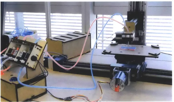
The printing platform was built around a three-axis gantry robot composed of two ball screw linear actuators for the x and y axis and a lead screw linear
actuator for the z axis (Figure 5). The z-axis actuator was attached to the back of the frame and a horizontal rod was attached to the z-axis to facilitate positioning of the extruder head. Each actuator is powered by a stepper motor. A re-purposed 3-axis
CNC motor driver controller with a spindle output is used to control the gantry.
Figure 5. Top view ofgantry system model with attached x-y motion stages for
actuating the build platform and a separate z-axis with attachment points for the mixer and extruder
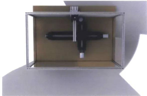
The extrusion and mixing system is comprised of material reservoirs connected to pressure sources, a mixing area, and a nozzle (Figure 6). Solenoid valves either switched manually or automatically, were used to control the pressure in the reservoirs and hence the flow rate of material dispensed. From the reservoirs,
the materials are then fed via tubing to a mixing system before being extruded from the nozzle.
Figure 6. Solenoid valves and material reservoirs. Flow rate of the two materials
(shown here in red and blue) were controlled through the actuation of solenoid valves connected to either compressed or atmospheric air. The reservoir and valve assembly may be expanded to accommodate additional materials.
Figure 7. Passive mixer. Static mixers with varying numbers of blade elements were
tested and compared to active mixing schemes accomplished by using motorized mixing blades.
Three different mixing strategies were explored: diffusive, static, and active. The diffusive strategy consisted simply of an additional length of tubing between the
nozzle and a "Y" connector joining the material feed tubes (see Figure 7). The active mixing strategy utilized a small reservoir immediately before the nozzle into which material could be fed. A set of blades driven by a small motor within the reservoir facilitates mixing. The static mixing strategy used inline static pipe mixers inserted between the nozzle and the material feed tubes.
An aluminum extrusion frame with sliding acrylic doors was designed to enclose the printing platform to provide structure, safety, and environmental control. Additional supports were added to the back of the frame to allow for attachment of the z-axis actuator. The acrylic doors were added in anticipation of working with UV-curable polymers to provide protection from UV radiation. The
enclosure that the frame and doors provide also makes it easier to introduce humidity, temperature, and other environmental controls in case more sensitive
materials are used.
The gantry platform is controlled using Mach3, a PC-based CNC software. For printing, tool paths were generated from 3D STL models or 2D contour models using PyCam, an open- source tool path generator for 3-axis CNC machining. The resulting GCode is sent to Mach3 and used to control the gantry movement. The viscosity and curing time of the materials being printed are taken into account when
setting appropriate line widths.
The material extrusion was separately controlled. The reservoir for each of the materials to be mixed was connected to two valves, one leading to
unpressurized atmospheric air and the other to a pressure source. Control of the valves and hence relative amount of each material was provided by a programmed Arduino microcontroller with either preprogrammed sequences or manual control buttons.
In this version of the printing platform, control of material mixing and
extrusion was provided separately, and coordinated with the tool path movement to produce the specified gradient. In future versions, the spindle output channel may be used to communicate directly with the extrusion system controller.
3.2.2.3 Gradient Fabrication
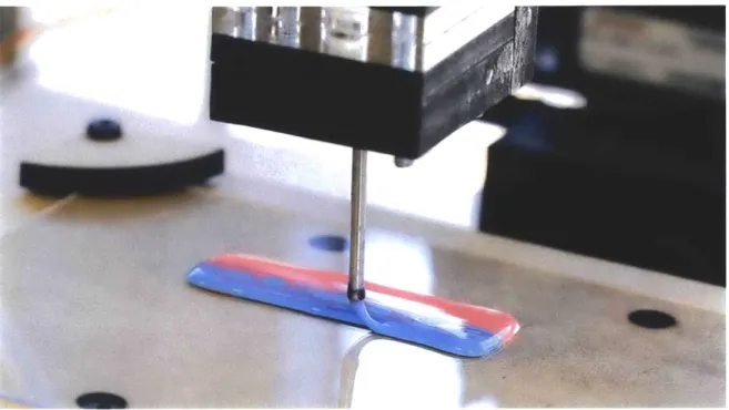
Figure 8. Color gradients being created on the 3D printed platform by mixing red and
blue adhesives in different controlled ratios.
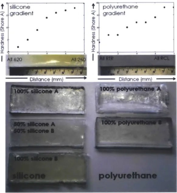
In Figure 8, the platform is shown printing with blue and red glue. The two adhesives are mixed in different ratios to produce varying color gradients. The cast sheet in Figure 9 demonstrates a similar principle, where a softer blue-colored silicone (Shore 00-10) is mixed with a harder red-colored silicone (Shore 00-50) to produce gradients in both color and durometer. Other combinations of materials tested for potential use on the platform include UV cure silicones and polyurethanes as shown in Figure 10. In the future, ratios of aggregates, foaming agents, or
Figure 9. Cast silicone sheet where a softer blue-colored silicone (Shore 00-10) is
mixed with a harder red-colored silicone (Shore 00-50) to produce gradients in both color and durometer.
For the adhesive used in the printer, passive mixing was sufficient to create color gradients. The inline static pipe mixers produced the most complete mixing with the smoothest gradients, however, the fluid flow and fill patterns in the mixers combined with the substantial length of the mixers (0.1905m to 0.2437m) made it difficult to control and change gradients quickly. The diffusive mixing strategy enabled adequate gradient production and rapid changes in gradient composition. The nozzle used in the current prototype was chosen from an assortment of stainless steel dispensing needles ranging from 7 gauge to 14 gauge, depending on the extrusion line thickness desired. For the fairly low viscosity and long drying time of the adhesive used, a 10 gauge needle was used.
silicone
gradient SSI
0 polyurethane gradient 0Figure 10. UV cure silicone and polyurethane samples tested. A series of samples were
made by combining UV curable silicones and polyurethanes with different shore values in a gradient across each sample. (Oxman, Keating, & Tsai, 2011)
While adequate for demonstrating variable property gradient printing, the gradient mixing strategies presented thus far are difficult to control and use a relatively large volume for mixing. In parallel to the development of the printer, several other gradient creation mechanisms are being explored. One method seeks
t
0)to generate controlled two-dimensional gradients prior to extrusion (Figure 11) rather than the 1 dimensional gradients produced by the current printer.
Figure 11. Two-dimensional gradients generated in a microfluidic device using red
and blue dyes. The geometry of the gradient is controlled by tuning the flow rates and pressures of multipleflow streams (Oxman, Tsai, & Firstenberg, 2012)
3.2.3 Physical Interfaces: Variable Impedance Test Socket 3.2.3.1 Motivation & Background
Prosthetic socket comfort and quality affects the ability of a patient to use his or her prosthesis and plays a role in preventing the development of future
pathological conditions. Unlike standardized prosthetic components such as knees or ankle-foot prostheses, prosthetic sockets are typically custom fabricated for each patient by individual prosthetists. The process of making such sockets, undertaken
by a prosthetist, is labor intensive and iterative and can take several weeks to
complete (Klasson, 1995). Incorrect socket attachments may cause sores and other discomforts in an amputee's daily routine (Johannesson, Larsson, & Oberg, 2004).
In stark contrast to the complex physiology of a residual limb, the resulting socket is typically composed of a homogenously rigid material. As the shape and volume of a residual limb can fluctuate during each step and between different levels of activity due to muscle contractions and other forces, there is a desire for
sockets to be able to comfortable accommodate a broad range of movements (Sanders, Harrison, Allyn, & Myers, 2009) (Staker, Ryan, & LaBat, 2009).
Although computer-aided design and computer-aided manufacturing
(CAD/CAM) tools are available, the design and fabrication of a functional socket still
remains largely an art. Quantitative anthropomorphic data collected via internal and surface image capturing technologies such as MRI, CT and ultrasound can provide some insight into tissue distribution within the residual limb. Here, residual limb stiffness plays a key role in scientifically determining final socket shape and material stiffness. Prior research suggests that there is an inverse relationship between residual limb stiffness and socket pressure along the socket- residual limb interface. For example, areas of the limb with boney protuberances require softer interfaces while softer tissues may be able to interface with stiffer materials.
Using spatiotemporal stiffness data collected about a residual limb, a process for the design and fabrication of a Variable Impedance Test Socket (VTS) is
explored. A mapping of collected limb data to appropriate socket structures and materials is used to inform design for the rapid prototyping and fabrication of a VTS.
Related Work
The concept of using softer materials in contact with support for boney protuberances and harder materials to support higher loads of softer tissues has been previously explored in socket technology through the use of "windowing." (Sewell, Noroozi, Vlnney, & Andrews, 2000) This windowing approach however, is coarse and fails to provide a necessary level of spatial control of dynamics. Another similarly coarse approach seeks to achieve distinct areas of mechanical response by assembling multiple parts composed of different materials (Laferrier & Gailey, 2010).
Conventional fabrication of prosthetic sockets are produced using a individually customized artisan process. More recently there has been research interest in automated socket fabrication via rapid prototyping. Sockets produced in this way tend to be composed of hard polymers such as ABS and homogenous in composition (Herbert, Simpson, Spence, & Ion, 2005). As part of his master's thesis,
David Sengeh (Biomechatronics Group, MIT Media Lab) produced a multi- material
3D printed socket using Objet's Connex500 polyjet technology (Sengeh, 2012). This
proposal seeks to produce a VTS that is further informed by ATS data and contains much higher resolutions in material and structural motif mapping.
There have been some research investigations into correlations between residual limb stiffness and ideal socket shape. These typically suggest that there is an inverse relationship between residual limb stiffness and localized socket
pressures (Sanders
J.
D., 1993) (Silver-Thorn, Steege, & Childress, 1996) (Mak, Liu, &Lee, 1994). This may allow the determination of ideal socket shapes by optimizing the maximum socket pressures when bearing the weight of the amputee using the
residual limb stiffness distribution measured by the ATS.
3.2.3.2 Process Overview
In conventional carbon fiber sockets, pressure distribution within the socket is controlled through areas of compression, contact and voids. More recent
technologies achieve varying degrees of compliance over certain anatomical features through changing socket wall thickness or adding mechanical features. "Windowing" techniques where patches of softer materials are added to a socket provides some variation of socket compliance over the residual limb but lack the necessary spatial control of dynamics to ensure a comfortable interface.
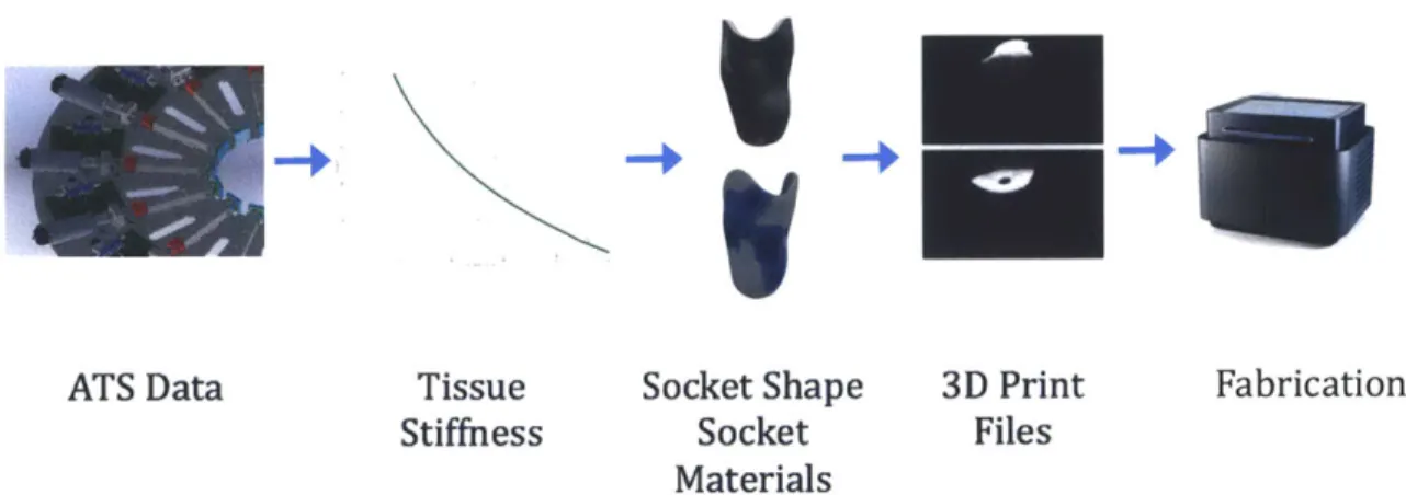
Fabricated using a Stratasys Objet500 Connex 3D printer, the Variable-Impedance Test Socket (VTS) is designed using data collected about a residual limb
(Figure 12). Taken over the entire limb, the data may be used to calculate the linear,
first-order stiffness of the tissue at each given point (Phillip & Johnson, 1981). The inner shape of the VTS socket is computationally determined from this data and the wall stiffness of the VTS is inversely proportional to the tissue stiffness measured. The VTS is passive and relatively lightweight allowing for dynamic testing under typical use conditions in a prosthetics facility.
The commercially sold Stratasys Objet500 Connex 3D printer and its affiliated software are capable of working with fourteen Digital Materials with a range of elastic modulus and durometer. The high resolution of the printer (600 dpi in X, 300 dpi in Y and 845 dpi in Z) allows for a high spatial resolution of material to tissue stiffness gradient matching. Smooth transitions between hard and soft
materials can be designed, avoiding the edges and hard transitions seen in
windowing techniques. The socket is printed layer-by-layer in the Z direction and all materials are incorporated in one process.
V1
ATS Data Tissue Socket Shape 3D Print Fabrication
Stiffness Socket Files
Materials
Figure 12. The VTS design and fabrication process begins with data collected on a
residual limb, including local tissue stiffness. This data may be derived
from
MRI scans or using an Actuated Test Socket (ATS) and is then used to computationally generate socket shape and socket material distribution. The socket shape and materialdistribution are incorporated into bitmaps or STL files that are then sent to a 3D printer for fabrication.
If quantitative feedback is required, especially with regard to peak pressures
over anatomical features of interest, off-the-shelf solutions may be employed, for example the Tekscan F-Socket Pressure Analysis System. Ongoing work in this direction is exploring the feasibility of incorporating 3D printed optical sensors into the current fabrication process of the VTS. Such sensors may be able to provide real-time feedback on socket wall deformation, shear stresses and pressure.
3.2.3.3 Data Collection ATS Data
In the final system, data will be collected physically using the ATS as
developed by Arthur Petron (Biomechatronics Group, MIT Media Lab). The socket shape under load in real time, the pressure response at different tissue
displacements and the local impedance of residual limb tissue may be measured. From these measurements, the local nonlinear first order stiffness at each location on the residual limb will be passed on to the VTS generation process.
Test Data
Since the ATS and VTS development tracks were scheduled to run in parallel, a set of realistic test data was constructed to allow data to socket structure and material mapping to commence. Test data was derived from three sets of data taken from the same residual limb: an MRI scan of the limb encased within a silicone liner, Tekscan F- Socket pressure distribution along the socket-limb interface under unloaded positions, and 3D scan data of the inner surface of an existing, well-fitting carbon fiber composite socket for the limb.
3D representations of the residual limb were reconstructed from MRI images
using the Mimics Innovation Suite software package developed by Materialise. Radial tissue thickness at each point on the limb was measured using the 3-matic software sub-package. Tissue thickness here is defined as the horizontal radial distance between the surface of the skin and the underlying bone.
A
MRI Scans
Tissue Thickness
Figure 13. (Left) Images from MRI scan of a right residual limb as seen in Mimics.
(Right -top) Representation of tissue thickness in the residual limb with areas of high tissue thickness denoted in red. Viewsfrom left to right are anterior, lateral, posterior, medial. (Right - bottom) 3D reconstruction of residual limb bone and tissue in 3-matic. The blue dots on the anterior view denote the points selectedfor K-value calculations. (Tsai & Oxman, 2013)
The 3D scan surface data from the existing carbon fiber socket was also imported into Mimics and the horizontal radial gap between the socket and the residual limb surface was measured using 3-matic. This distance is referred to in the following passages as "tissue displacement" (Figure 13)
15-0 510- 80 00 E o 0 0 0 0 0 0 0 0 00 5* 00 ~ 5 0000 0 0 I-0 0 00 0 0 09 0 0 8 10 12 14 16 18 20 22 24 26 28 Tissue Thickness (mm)
Figure 14. Tissue Displacement VS Tissue Thickness for points along the tibial crest
and femural condyles.
Pressure data from the Tekscan F-socket system in the form of tab-separated text files were opened in Excel. Normal forces at these points were derived by dividing the pressures over the measurement area. Several points as seen in Figure
14, particularly over anatomical areas of interest such as over the tibial crest and
along the femoral condyles were selected. Stiffness values (K) at these areas were calculated using the force (F) and tissue displacement (R) data using Hooke's law K
= F/(R). The best-fit equation for these values was estimated to be K = -141.6 ln(R) +
250 200-500 50 0 0 L 0 0 15 20 25 Tissue Thickniess (mm)
Figure 15. Stiffness VS Tissue Thickness
for
points along the tibial crest andfem
ural condyles as indicated by thefigure
in the upper right.Data Structure
The data structure for communication between the ATS and VTS generation method is a tab delimited text file with columns for plateID, 0, r, z, F and t. PlateID denotes the ATS actuator ID the measurement was taken using; 0, r and z are the coordinates of where the data was taken in degrees and mm (Figure 16); F (N) is the force used; and t is the time in seconds from the beginning of the measurement sequence. The test data set was written using the same structure with null values for
Y
4
YX
Figure 16. Origin and axis for data structure. The origin is taken to be the center of
the limb at a height equal to the top of thefuture socket cut lines as determined by a prosthetist. 0 increases clockwisefrom the center of the patella when viewedfrom the top. (Left) Anterior view. (Right) Top view.
3.2.3.4 Modeling
The ability to accurately model the biomechanics of the soft tissues of a residual limb is important in understanding the dynamic interaction between the limb and the socket and should play a role in informing future designs of both the
VTS and potential active sockets and interfaces. The properties of skin depend
primarily on the interactions of dermal collagen and elastic fiber networks within the ground tissue matrix with some contributions from the epidermis (Chen, 2008). At small displacements, the behavior is roughly linear elastic as the elastin and reticular fiber matrix deforms. At larger deformations, tissues experience strain hardening and there is a static nonlinearity that scales with depth into the tissue (Elsner, Berardesca, & Wilhelm, 2002).
When considering in vivo indentation testing as is the case with the ATS, there are several additional issues that arise including the effects of Langer's lines,
muscularity, and isotropy in fleshy areas (e.g. the posterior compartment of the leg) and contributions to stiffness from bone in areas of thin tissue thickness (Hayes, Keer, Hermann, & Mockros, 1972). In the analysis done in section 3.2.3.3 above using the test data set constructed from MRI images, a simple linear elastic material model is used to approximate stiffness values at each point. There is some basis in the literature for this as linear properties typically contribute the largest role
towards daily physiological stress levels (Blschoff, Arruda, & Grosh, 2000). In reality however, soft tissues typically have non-linear stress-strain and viscoelastic
behaviors, calling for geometrically non-linear approaches (Doblare & Garcia-Aznar,
2008).
In this section, a number of commonly used hyperelastic and viscoelastic material models are presented and discussed in view of suitability towards fitting experimental ATS data.
Material Models for Biological Tissues
Hyperelastic materials are ideally elastic materials for which there exists a strain energy density function W, the derivative of which in respect to a strain component E is the stress component S. The hyperelastic idealization assumes a stress-strain relationship that is non-linearly elastic, incompressible, isotropic and more or less independent of strain rate. Hyperelastic assumptions are generally suitable for pseudoelastic tissues and widely used models include the Neo-Hookean, Mooney-Rivlin, Ogden and Arruda-Boyce models (Xu, Teoh, & Sun, 2002) (Weiss, Gardiner, & Quapp, 1995).
Mooney-Rivlin and Ogden and two of the most commonly used
phenomenological models for biological tissues. Mooney-Rivlin is generally suitable for strains up to 200% and Ogden up to 700% (Mooney, 1940) (Ogden, Non-Linear Elastic Deformations, 1984). For certain material constants and strain invariant constraints, the 6-parameter Ogden model simplifies to the 2-parameter
recommended and results may not be as robust as those of mechanistic models (Korochkina, Claypole, & Gethin, 2005) (Ogden, Saccomandi, & Sagura, 2004).
The Neo-Hookean and Arruda-Boyce models are mechanistic models derived from the statistical thermodynamics of cross-linked polymer chains and 8-chain networks within a representational volume, respectively. For small displacements, the Arruda-Boyce model reduces to the Neo-Hookean model. Based on its
underlying cross-linked polymer framework, the Neo-Hookean model is typically only accurate at lower strains (< 20%) (Treloar, 1948) (Arruba & Boyce, 1993). The Arruda-Boyce model on the other hand is generally accurate up to strains of 300% when used to describe rubbers and polymeric materials. Compared to the empirical Mooney-Rivlin and Ogden models, the mechanistic models deliver decent curve fits even with limited experimental data and typically provide reasonable
approximations of behavior in other modes of measurement (e.g. prediction of behavior under uniaxial tension using data collected from equibiaxial tensile testing) (Marlow, 2003).
When considering the dynamic response of biological tissues, it becomes apparent that it may be beneficial to model the frequency-dependent system response. There are three typical viscoelastic solid material models that have been investigated extensively with regard to biological tissues in the literature: Maxwell, Kevin and Voigt (Elsner, Berardesca, & Wilhelm, 2002). When a high degree of modeling accuracy is desired, hybrid hyperelastic linear or nonlinear viscoelastic models may also be constructed (Weiss, Gardiner, & Quapp, 1995) (Xu, Teoh, & Sun, 2002). These systems allow for the modeling of behaviors such as creep, hysteresis and stress-relaxation, which may be useful when considering the design of active prosthetic sockets, which may change in stiffness or geometry to accommodate different modes of use.
In the case of data taken using the ATS, precise unperturbed tissue thickness (radial from the surface of the skin to the surface of the underlying bone) and hence the strain will be difficult to obtain given the in vivo nature of the measurements.