Publisher’s version / Version de l'éditeur:
Vous avez des questions? Nous pouvons vous aider. Pour communiquer directement avec un auteur, consultez la première page de la revue dans laquelle son article a été publié afin de trouver ses coordonnées. Si vous n’arrivez pas à les repérer, communiquez avec nous à PublicationsArchive-ArchivesPublications@nrc-cnrc.gc.ca.
Questions? Contact the NRC Publications Archive team at
PublicationsArchive-ArchivesPublications@nrc-cnrc.gc.ca. If you wish to email the authors directly, please see the first page of the publication for their contact information.
https://publications-cnrc.canada.ca/fra/droits
L’accès à ce site Web et l’utilisation de son contenu sont assujettis aux conditions présentées dans le site
LISEZ CES CONDITIONS ATTENTIVEMENT AVANT D’UTILISER CE SITE WEB.
Research Paper (National Research Council of Canada. Division of Building
Research); no. DBR-RP-424, 1970-01-01
READ THESE TERMS AND CONDITIONS CAREFULLY BEFORE USING THIS WEBSITE. https://nrc-publications.canada.ca/eng/copyright
NRC Publications Archive Record / Notice des Archives des publications du CNRC : https://nrc-publications.canada.ca/eng/view/object/?id=db62261b-9858-4b7f-8465-d4e4cdc2af41 https://publications-cnrc.canada.ca/fra/voir/objet/?id=db62261b-9858-4b7f-8465-d4e4cdc2af41
NRC Publications Archive
Archives des publications du CNRC
This publication could be one of several versions: author’s original, accepted manuscript or the publisher’s version. / La version de cette publication peut être l’une des suivantes : la version prépublication de l’auteur, la version acceptée du manuscrit ou la version de l’éditeur.
For the publisher’s version, please access the DOI link below./ Pour consulter la version de l’éditeur, utilisez le lien DOI ci-dessous.
https://doi.org/10.4224/40001474
Access and use of this website and the material on it are subject to the Terms and Conditions set forth at
Elevated-temperature tensile and creep properties of some structural
and prestressing steels
T.
2.
H a ~ m a t h y l and
W . W .
Stanaak2
Elevated-Temperature Tensile and
Creep Properties of Some Structural
and Prestressing Steels
REFERENCE: Harmathy, T. Z. and Stanzak, W. W., "Elevated-Tempera- ture Tensile and Creep Properties of Some Structural and Prestressing Steels," Fire Test Performance, ASTlli1 STP 464, American Society for Test- ing and Materials, 1970, pp. 186-208.
ABSTRACT: The tensile and creep characteristics of two structural steels (ASTM A36 and CSA G40.12) and a prestressing steel (ASTM A421), all three used extensively in the building industry, have been investigated. In- formation is presented concerning the initial portion of the stress-strain curve, the ultimate and yield strengths, the elongation, the reduction of area, and the two stress-dependent creep parameters, Z and EL,, for tempera-
tures up to 1200 and 1300 F.
The tensile data obtained for ASTM A36 steel seemed to agree with other reported data. The G40.12 steel exhibited somewhat unusual tensile behav- ior at about 700 F. For the ASTh.1 A421 steel the natural scatter of the test data overshadowed the eEect of crosshead speed (0.02 to 0.75 in./min) at temperatures below 700 F.
Harmathy's creep model seemed fairly well applicable to all three steels, and Clauss' rule concerning the creep rupture time to the two structural steels.
KEY WORDS: tensile properties, creep properties, structural steels, pre- stressing steels, elevated-temperature tests, yield strength, ultimate strength, elongation, reduction of area, secondary creep rate, evaluation, tests
Nomenclature
AH Activation energy of creep, Btu/lb mole
R Gas constant, Btu/lb mole deg R
t Time, h
t, Time of creep rupture, h
1 Research officer, Fire Section, Division of Building Research, National Research Council of Canada, Ottawa, Ont., Canada.
2 Steel industry fellow, Fire Section, Division of Building Research, National Re- search Council of Canada, Ottawa, Ont., Canada.
Temperature, deg R (unless otherwise stated) Zener-Hollomon parameter, h-l
Reduction of area, dimensionless Total load strain, dimensionless Time-dependent strain, dimensionless Creep parameter (see Ref 13), dimensionless Secondary creep rate, h-l
Temperature compensated time, h Elongation, dimensionless
Stress referred to original cross sectional area, psi Ultimate strength, psi
Yield strength, psi
As described elsewhere in detail [I, 213 the process of deterioration of steel-supported building elements in fire can be predicted with reason- able accuracy, if the plastic behavior of the steel at elevated temperatures is known. Although a substantial amount of information is already avail- able concerning various properties of ordinary carbon steels [ 3 4 ] and of prestressing wires [7-121 at elevated temperatures, this information is either not applicable to the common commercial steel products, or is presented in a form not immediately utilizable in the calculations de- scribed in Refs 1 and 2.
To provide information to design engineers, primarily to those con- cerned with various aspects of fire endurance of building elements, a research program was undertaken several years ago in the authors' laboratory. This program was later expanded to include some work done under the Steel Industries Fellowship arrangement between the indus- tries and the National Research Council of Canada.
This paper is the presentation of the test results developed during the past several years. A; this stage there will be no effort made to interpret the experimental findings in the light of the theories of plasticity. Materials and Testing
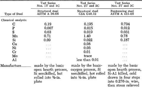
Three carbon steels, used extensively in the building industry, were selected for testing. Some basic information concerning these materials is given in Table 1; the photomicrographs in Fig. 1 show their grain structure.
All test specimens were prepared with their axes parallel to the direc- tion of principal flow during the hot or cold work. In the case of the materials in Test Series Nos. IT, lC, 2T, and 2C the test result is not expected to depend noticeably on the orientation of the specimen axis.
3 The italic numbers in brackets refer to the list of references appended to this paper.
188 FIRE TEST PERFORMANCE
TABLE 1-Some infomation concerning the materials.
Structural steel Structural steel Prestressing steel
Type of Steel ASTM A 36-66 CSA G40.12 ASTM A 481-65 Chemical analysis: C P S Mn Si Cu Ni Cr Mo A1
Manufacture ... made by the basic
open hearth process, Si semikilled, hot rolled into %-in. plate 0.195 0.794 0.015 0.012 0.019 0.031 1.40 0.78 0.022 0.187 0.08 . . . 0.03 . . . 0.01 . . . trace . .
.
less than 0.01 . . .made by the basic- made by the basic oxygen process, Si open hearth process, semikilled, hot rolled Si-A1 killed, cold into %-in. plate drawn in four steps
into 0.276-in. wire, then stress relieved
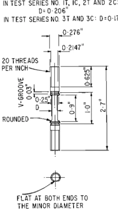
The size of the test specimens is shown in Fig. 2.
The tension tests were carried out on a 30,000-lb screw power uni- versal testing machine, equipped with a 16-in. long, 3-in. inside diameter cylindrical furnace. The deformation of the specimens was measured by a differential transformer type high-temperature extensometer. The ends of the Inconel extension arms of the extensometer were clamped firmly into the grooves of the specimen (Fig. 2 ) .
In Test Series 1T and 2T the temperature of the specimen was mea- sured by one thermocouple attached to the midlength of the specimen. In Series No. 3T (which was completed first) three thermocouples were used, one attached again to the midlength of the specimen and two to the holders near either end of the specimen. The temperature of the furnace was controlled from a separate thermocouple located in a hole in the furnace wall.
After the installation of the specimen the temperature of the furnade was raised quickly to the target level. The test did not start, however, until the specimen thermocouple indicated the development of quasi- steady-state conditions in the furnace, usually 60 to 90 min after heating was begun.
I n all three tension test series the temperature a t the midlength of the specimen was regarded as "the specimen temperature." In about 75
percent of the tests in Series No. 3T the maximum difference in the tem- perature at this point and at the holders was less than t 10 F. In 1 out
190 FIRE TEST P E R F O R M A N C E
FOR T H E SPECIMENS IN TEST SERIES NO. IT, IC, 2 T AND 2 C :
D = 0 . 2 0 6 "
IN TEST SERIES NO. 3 T AND 3 C : ~ = 0 . 1 7 5 "
1
K:l1
2 0 THREADS
1
F L A T AT BOTH ENDS TO T H E MINOR DIAMETER
FIG. 2-Sizes of test specimens.
of the 42 elevated-temperature tests (in Series No. 3T) this maximum temperature difference was as high as 30 F.
The tension tests were carried out at the constant crosshead speeds listed in Table 2. To investigate the effect of strain rate on the plastic characteristics of prestressing steel, in Series No. 3T three tests were carried out (at three different crosshead speeds) at each temperature level. The time that elapsed between the start of the test and the rupture of the specimen always was recorded. From this information and from the elongation the average strain rate was calculated. The range of the average strain rates is reported also in Table 2.
TABLE 2-Some i n f o m i o n concerning the tension tests.
Test Series Test Series Test Series
No. 1T No. 2T No. 3T
Crosshead speed, in./min ... 0.075 0.05 less than 0.025 0.075 0.75
Measured average strain rate,
in./in. min 0.072 to 0.102 0.051 to 0.076 0.019 to 0.029 0.056 to 0.098 0.37 to 0.70
In general, from the yield point to the point of ultimate stress the actual strain rate was reasonably constant and approximately equal to that corresponding to the crosshead speed. Up to the yield point it was usually lower and beyond the point of ultimate stress usually higher. The average strain rate was therefore dependent on the relative length of these three sections of the stress-strain curve, and thus also on the temperature.
The creep tests were carried out on a universal creep machine equipped with a furnace similar to that described previously. The mea- surement of the deformation and of the temperature also was done by a similar method. The signal from the extensometer was recorded by a creep time recorder which had two chart speeds and two strain ranges. To obtain a more detailed record of the primary creep process, the initial period of the deformation process was recorded usually by using high chart speed and high strain magnification ratio.
It was intended originally to load the specimen always 1 h after its installation into the preheated furnace. Unfortunately, it was found that
1 h was not sufficient time to eliminate the temperature oscillations fol- lowing the installation of the specimen, and to achieve sufficient unifor- mity of temperature along the specimen length. As a result, in Test Series No. 3C (this series was conducted first) the time that elapsed between
I
the installation of the specimen in the furnace and the loading varied from 1 to 24 h. In Series Nos. 1C and 2C this period was always 24
+
0.5 h.In all three creep test series, three thermocouples (arranged as for Test Series No. 3T) were used to measure the temperature at and in the vicinity of the specimen. The variation of the temperature along the test assembly was generally not too significant. In about 85 percent of the 68 elevated-temperature creep tests the maximum difference in tem- perature at the midlength of the specimen and at any of the holders was less than 10 F: only in one case was it as high as 22 F.
Here too, the temperature at the midlength of the specimen was re- garded as "the specimen temperature." The constancy of this tempera- ture was not entirely satisfactory. On an average, in one out of four cases the maximum deviation from the average specimen temperature was greater than t 2 F; in two tests this deviation was 4 F. In preparing these statistics, the temperatures during the earliest stage of the creep were disregarded. At this stage even greater temperature changes often - were recorded.
Although the testing procedures were not up to the usual standards, it is believed that they were adequate for the intended use of the data, that is, for the prediction of the deformation history of steel structures in fire.
192 FIRE TEST PERFORMANCE
Whenever the temperature variation was significant enough to affect the test result, the rate of secondary creep was evaluated over a period of sufficiently constant specimen temperature.
I t was found earlier [13] that the rate of secondary creep is not too sensitive to the previous stress or strain history of the material. To reduce the number of creep tests, therefore, a few specimens in Series No. 2C were tested at a number of different loads. After secondary creep condi- tions were attained with the original load, the load was increased and maintained at the new level until secondary creep conditions again de- veloped. In some cases the rate of secondary creep at four or five dif- ferent loads thus could be determined before the onset of tertiary creep conditions.
I n most runs in Series Nos. 1C and 2C the test was carried on u p to the point of rupture.
Results of Tension Tests
The stress-strain curves obtained in the tension tests are reproduced, up to 0.10 to 0.12 in./in. strains, in Figs. 3 to 7. Such complete stress- strain curves are generally not available and therefore, could be of some interest to design engineers concerned with rapid plastic deformations. Since the modulus of elasticity is known to be relatively insensitive to the microstructure of steel, and its variation already is known from vari- ous sources [14-161, no effort was made to evaluate it from the records. In Test Series No. 3T, where the tests were carried out at three dif- ferent crosshead speeds, the strain rate (within the range investigated) did not seem to affect considerably the shape of the curves until tem- peratures reached about 700 F (see Figs.
5,
6, and 7).I n Figs. 8, 9 and 10 the variation with temperature of the ultimate strength, o;, and of the yield strength,
o;
(at 0.2 percent permanent set), are plotted. Similar plots in Figs. 11, 12, and 13 show the variation of the elongation and of the reduction of cross section at rupture for the three steels examined. The dashed and dotted lines in Figs. 8 and 11represent bands of experimental points obtained by another laboratory at a slightly higher crosshead speed (0.09 in./min) for a similar material, using standard rectangular tension test specimens with 2-in. gage lengths, as specified in ASTM Tension Testing of Metallic Materials
( E 8-68). The discrepancies in the results are not unusual, and are probably due to differences in the chemical composition and grain char- acteristics of the materials, as well as to the differences in the sizes of the test specimens and in the testing procedure.
The dotted and dashed curves in Figs. 10 and 13 indicate the bands in which the large majority of experimental points are expected to fall, if the tests are performed at about 0.02 to 0.75 in./min crosshead speeds.
These plots also show clearly that up to about 700 F the natural scatter of the points overshadows the effect of crosshead speed.
A significant increase in the strength of the examined CSA (340.12 steel at about 700 F seemed somewhat unusual. It was, nevertheless, clearly verified by repeated runs.
Results of Creep Tests
Based on Dorn's creep theory [17-191 Harmathy [13] has derived the following equation for the description of the primary and secondary creep of metals:
where Z and eta are functions of the stress alone (that is, independent of the temperature).
Thus
= Z(a) (2)
Z is the well-known Zener-Hollomon parameter [20]. It is defined as
= ;ts
e
A H / R T ( 4 )The variable, 8, is the so-called "temperature-compensated time," and is defined as
AH is the activation energy of creep and, as Sherby and Dorn [21] have shown, over about one half of the melting temperature of the metal, it is approximately independent of the temperature.
It was also shown in Ref 13 that E q 1 yields an accuracy acceptable in engineering calculations even if du/dt # 0 but is a slowly varying function of the time. Under these circumstances E q 1 can be looked upon as a mechanical equation of state and can be used to describe any plastic deformation process (tertiary creep excepted) with the aid of two stress-dependent parameters. Thus the purpose of creep research becomes equivalent to finding the explicit form of the Z ( 5 ) and et0 ( 5 ) relationships.
202 FIRE T E S T P E R F O R M A N C E
I n a strict sense, it is permissible to combine the temperature and time into a single variable only if the material is physiochemically stable in the temperature interval of interest. I t is well known that above 700 F carbon steels do not perfectly fulfil this condition. Upon prolonged heat- ing at temperatures above 800 F (according to Cahill [8] even at tem- peratures as low as 570 F ) the pearlite loses its fine lamellar structure. The cementite lamellae coalesce into globules. This so-called "spheroidi- zation" of the cementite may take several days at 800 F, but takes place in a few hours at 1200 F, and manifests itself in the softening of the material [7, 8, 121. This effect is marked especially in the case of pre- stressing steel, the strength of which results, to a great extent, from the fineness of its lamellar pearlite structure. Further heating above 1350 F results in the formation of austenite and the annihilation of the original grain structure.
Even 'though the application of Harmathy's creep model to carbon steels in the 700 to 1300 F range is not justified fully, in the lack of other comprehensive theories applicable to creep deflection problems its re- tention cannot be avoided. In applying this model, the original meaning of A H will be overlooked and A H / R will be regarded simply as an empirical constant.
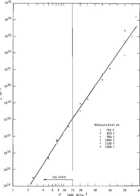
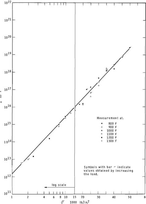
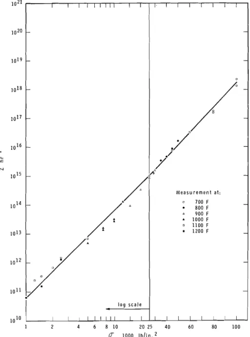
The experimental data concerning the variation of the Zener-Hollomon parameter for the three materials tested are presented in Figs. 14, 15, and 16. The analytical expressions of the solid lines shown in the figures are summarized in Table 3. These expressions do not necessarily repre- sent the "best curves" through the points. They have been selected with a view to describing the entire course of the curves by not more than two equations.
In Fig. 15 the points obtained from tests carried out by stepwise in- crease of the load are distinguished by a stroke attached to the symbols. I t is seen that these points follow satisfactorily the course of the other points obtained by the normal test practice. This finding is another cor- roboration of the assumption that the secondary creep rate is independent of the previous stress-strain history of the material.
Some analyhcal expressions concerning the € t o ( u ) function are given
also in Table 3. These expressions have been estimated from widely scattered data. This enormous scatter, which is not unusual, is probably attributable to the following:
( a ) With differential transformer type extensometers the strain record may be substantially falsified by the bending and uneven heating of the extensometer arms during the initial period of rapid deformation.
( b ) The imposition of the load is never truly instantaneous, but takes place at a finite rate, often even in a number of separate steps. I t was recognized earlier [I31 that € t o is a property extremely sensitive to d a / d t .
204 FIRE T E S T P E R F O R M A N C E 1022 1021 1020 10l9 1018 I I 1 1 1 1 1 1 1 -
-
- - I I I I I I I I - - di
-
,'
- .Y 1017 --
10l6 - - M e a s u r e m e n t at: * 800 F - 900 F A 1000 F 1100 F 1200 F Q 1 3 0 0 F - - S y m b o l s w i t h b a r ' i n d i c a t e v a l u e s o b t a i n e d b y i n c r e a s i n g 10l2 10l1 1 2 4 6 8 10 15 20 30 40 50 6 0 I000 l b l i n ?FIG. 15-Zener-Hollomon parameter versus stress relation for a CSA G40.12 steel.
-
l o g s c a l e-
I I 1 1 1 1 1 1 1 t h e l o a d . I I I I I I I I206 FIRE T E S T P E R F O R M A N C E m I
%
1.:
1113
UL0 Lo L: l- r( b 0 b 0 r(5
$
0,-
0, x , X x r: r(*
-
c) C? I I I1 II 0 u- u-a 2 .-.-
.- i;, i;,s
o
0 0 0 0 o o O m o o.
.
.c 0, EV/ EV/ &V/ g b O b O bs;,v
E v E v
o - a o" 8
v
g
v/g
v/ 0 b 3 b 3 b % 3 % 3 % 3 % b m 4 b 0 C1 r( 0 0 0 0 0 0 0 0 %, 0 0 (D 32'
Lo-
? $? 2
5
-* m & X b X X " c )Zo,
m - qc? ,cqGc?
0 - " c ) corn I1 II II II ) I I1 N N N N N N 0 0 0 0 0 0 0 0 0 0 t- m (0 m m$
z
"
w .2'5
'5
5 V) V) V) 1 1 1 VIE
2
g
I n general, as predicted [13], EL, seemed to decrease with the decrease
of load, irrespective of the temperature. I n the higher temperature range, however, several unusually high values of eta ( a t relatively low loads) also were recorded in addition to those which fall in line with the expectation. The creep rupture data obtained in Test Series Nos. 1C and 2C indi- cated that the usual assumption, that the creep rupture time varies in- versely as the rate of creep [22], is a valid one. I t was found that the equation
0.15
t, =
it,
(6)
yields a fair engineering accuracy, at least for the materials examined.
Acknowledgment
The authors wish to thank J. E. Berndt for his assistance in conducting the experimental work. This paper is a contribution from the Division of Building Research, National Research Council of Canada, and is published with the approval of the director of the division.
The second author, W. W. Stanzak, steel industries fellow, was in- volved in a cooperative research program with the steel industry on the performance of steel under fire exposure.
References
[I1 Harmathy, T. Z., "Deflection and Failure of Steel-Supported Floors and Beams in Fire," Fire Test Methods-Restraint and Smoke 1966, ASTlM STP 422, American Society for Testing and Materials, 1967, p. 40.
[21 Harmathy, T. Z., "Creep Bending of Non-Uniformly Heated Beams," in prepa- ration.
[3] "Compilation of Available High-Temperature Creep Characteristics of Metals and Alloys," compiled by Creep Data Section of Joint Research Committee on Effect of Temperature on the Properties of Metals, published jointly by Ameri- can Society for Testing and Materials, and American Society of Mechanical Engineers, 1938.
141 Simmons, W. F. and Cross, H. C., "Elevated Temperature Properties of Carbon Steels," Elevated Temperature Properties of Carbon Steel, ASTM STP 180,
American Society for Testing and Materials, 1955.
[5] Smith, A. I., Jenkinson, E. A,, and Armstrong, D. J., "Creep and Rupture Properties of Carbon Steels," Proceedings, Institution of Mechanical Engineers, Vol. 174, 1960, p. 745.
[6] Glen, J. et al, "Elevated-Temperature Tensile, Creep, and Rupture Properties of Various Carbon Steels," High-Temperature Properties of Steels, Proceedings of the joint conference organized by the British Iron and Steel Research Asso- ciation and the Iron and Steel Instih~te, Eastbourne, 1966, p. 159.
[7] Day, M. F., Jenkinson, E. A., and Smith, A. I. S., "Effect of Elevated Tempera- tures on High-Tensile-Steel Wires for Prestressed Concrete," Proceedings, In- stitution of Civil Engineers, Vol. 16, 1960, p. 55.
[a] Cahill, T., "The Behaviour of Prestressing Wire at Elevated Temperatures," Fire Resistance of Prestressed Concrete, Kordina, K., ed., Bauverlag GmbH., Wiesbaden, 1966, p. 101.
208 FIRE T E S T P E R F O R M A N C E
Strand for Prestressed Concrete," Journal, Portland Cement Association, Re- search and Development Laboratories, Sept. 1961, p. 8.
[lo1 Soretz, S., "Zugversuche an Betonsthlen mit Dauerlast und Steigender Tern-
peraftur," Schweizer Archiv fiir anget~andte Wissenschaft und Technik, Vol. 33,
eft
4, 1967, p. 1. -[ I l l Bates, S. C. C, and Corson, R. H., "Effect of Temperature on Prestressing
Wires," Proceedings. Institution of Civil Engineers' Conference on Prestressed concrete Pressure vessels, 1967, p. 21. -
1121 Abrams, h4. S. and Erlin, B., "Estimating Post-Fire Strength and Exposure
Temperature of Prestressing Steel by a Metallographic Method," Journal, Port- land Cement Association, Research and Development Laboratories, Sept. 1967, p. 23.
I131 Harmathy, T. Z., "A Comprehensive Creep Model," Transactions, American
Society of Mechanical Engineers, Journal of Basic Engineering, Vol. 89, 1967, p. 496.
[I41 Lea, F. C. and Crowther, 0 . H., "The Change of the Modulus of Elasticity
and Other Properties of Metals with Temperature," Engineering, Vol. 98, 1914, p. 487.
[15] VersC, G., "The Elastic Properties of Steel at High Temperatures," Transac-
tions, American Society of Mechanical Engineers, Vol. 57, 1935, p. 1.
1161 Garofalo, E., Malenock, P. R., and Smith, G. V., "The Influence of Tempera-
ture on the Elastic Constants of Some Commercial Steels," Determination of
Elastic Constants, ASTM STP 129, American Society for Testing and Materials, 1952, p. 10.
[171 Dorn, J . E., "Some Fundamental Experiments on High-Temperature Creep,"
Journal of the Mechanics and Physics of Solids, Vol. 3, 1954, p. 85.
[18] Dorn, J. E., "Progress in Understanding High-Temperature Creep," Gillett
Memorial Lecture, American Society for Testing and Materials, 1962.
[19] Dom, J. E. and Mote, J. D., "Physical Aspects of Creep," High Temperature
Structures and Materials, Freudenthal, A. M., Boley, B. A., and Liebowitz, H.,
eds., MacMillan Co., New York, 1964, p. 95.
[20] Zener, C, and Hollomon, J. H., "Effect of Strain Rate on the Plastic Flow of
Steel," Journal of Applied Physics, Vol. 15, 1944, p. 22.
[21] Sherby, 0. D , and Dom, J. E., "An Analysis of the Phenomenon of High
Temperature Creep," Proceedings, Society f o r Experimental Stress Analysis, Vol. 12, 1953, p. 139.
[22] Clauss, F. J., "An Examination of High-Temperature Stress-Rupture Corre-
lating Parameters," Proceedings, American Society for Testing and Materials, Vol. 60, 1960, p. 905.