Automatic UAV Image Registration Using Feature
Detection and Matching with Satellite Imagery
by
Jordan W. Lucier
B.S. Computer Science and Engineering, Massachusetts Institute of
Technology (2017)
Submitted to the Department of Electrical Engineering and Computer
Science
in partial fulfillment of the requirements for the degree of
Master of Engineering in Electrical Engineering and Computer Science
at the
MASSACHUSETTS INSTITUTE OF TECHNOLOGY
June 2018
c
○ Massachusetts Institute of Technology 2018. All rights reserved.
Author . . . .
Department of Electrical Engineering and Computer Science
May 25, 2018
Certified by . . . .
Hari Balakrishnan
Professor of Computer Science
Thesis Supervisor
Certified by . . . .
Samuel Madden
Professor of Computer Science
Thesis Supervisor
Accepted by . . . .
Katrina LaCurts
Chairman, Department Committee on Graduate Theses
Automatic UAV Image Registration Using Feature Detection
and Matching with Satellite Imagery
by
Jordan W. Lucier
Submitted to the Department of Electrical Engineering and Computer Science on May 25, 2018, in partial fulfillment of the
requirements for the degree of
Master of Engineering in Electrical Engineering and Computer Science
Abstract
This thesis presents an approach and implementation for using satellite imagery to perform image registration with unprocessed aerial images captured with a UAV. Aerial imagery is used in a large variety of applications including disaster relief, urban planning, crop and vegetation monitoring, and mapping. The common difficulty in utilizing aerial imagery captured by aircraft rather than satellite is that of image registration: transforming data into the image coordinate system. Often, the goal of these applications involves transforming location data into the image coordinate system for object extraction and further processing. Current approaches require hand-labeling of correspondences, the use of ground control points (GCPs), or human analysis to identify objects or locations of interest in the aerial imagery. As such, these methods do not sufficiently scale, generalize, or provide the efficiency required for these applications. The proposed approach to image registration in aerial imagery makes use of raw images captured on consumer-grade UAVs, and uses automatic feature detection and matching to register the imagery. This implementation provides a proof of concept, which was found to succeed on roughly 65% of our images.
Thesis Supervisor: Hari Balakrishnan Title: Professor of Computer Science
Thesis Supervisor: Samuel Madden Title: Professor of Computer Science
Acknowledgments
Thank you to Sam Madden and Hari Balakrishnan for their support this year and making this project possible. Additionally, thanks to Favyen Bastani for his helpful suggestions that led to the eventual implementation of this project.
This research was supported in part by the Qatar Computing Research Institute (QCRI).
Contents
1 Introduction 11
1.1 Related Work . . . 12
1.1.1 Image Registration Overview . . . 12
1.1.2 Image Feature Detection And Matching . . . 15
1.1.3 Orthoimages . . . 17
1.2 Summary of Contributions . . . 19
2 Design and Implementation 21 2.1 Initial Approach . . . 21
2.2 Feature Detection and Matching Approach . . . 22
2.3 Robustness and Extensions . . . 25
2.3.1 Failures . . . 25
2.3.2 Solutions to Failures . . . 30
3 Evaluation and Discussion 35 3.1 Evaluation . . . 35
3.2 Discussion . . . 37
3.2.1 Reliance on Reference Imagery . . . 37
3.2.2 Feature Matching Difficulty and Observations . . . 37
3.2.3 Scale Invariance and Satellite vs UAV Perspective . . . 38
4 Conclusion 41 4.1 Conclusion . . . 41
4.2 Future Work . . . 41 4.3 Contributions . . . 42
List of Figures
1-1 Example of a GCP (left) and GCPs labeled in an aerial image (right) [4]. . . 13 1-2 Feature detection example. An image (top) is processed and distinctive
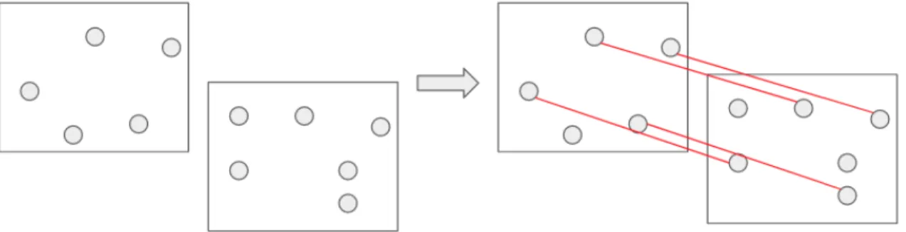
features are detected (bottom, shown in grayscale for easier viewing). Keypoints are shown as green circles in the right image, the diameter of the circles represents the size of the keypoint. . . 16 1-3 Feature matching example. Two sets of image features and descriptors
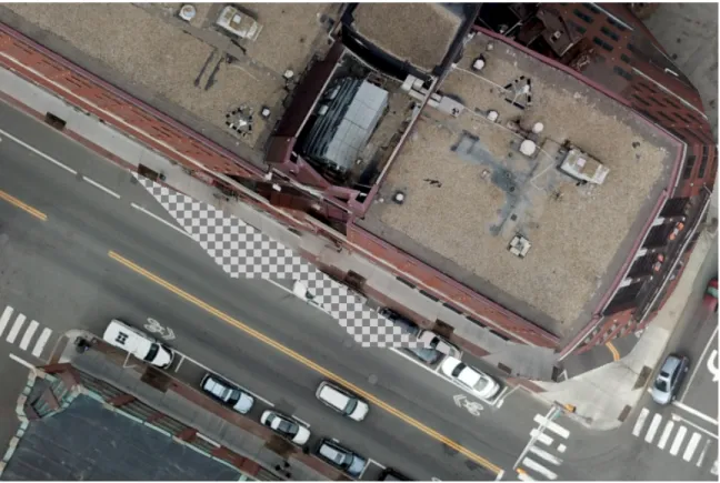
(left) are matched and the matching is shown as linked pairs of feature points (right). . . 17 1-4 Example of artifacts introduced by constructing an orthoimage using
surface meshing (checkered pixels are empty). . . 18
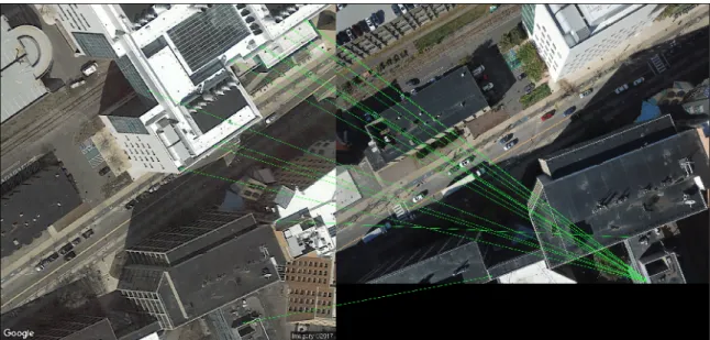
2-1 Example of feature matching between a satellite image (left) and UAV image (right) of the same area. . . 22 2-2 Mapping location data from satellite (left) to UAV image (right) . . . 25 2-3 (a) A satellite image corresponding to the center-point of UAV image
(b). (c) The detected feature matching between images (a) and (b). (d) Image (a) with GPS parking spot bounds overlayed. (e) The same parking spots mapped into (b) using the homography computed from (c). . . 26 2-4 Failed image feature matching . . . 27 2-5 Example of low quality matching occurring as a result of matched
2-6 Example of low quality matching occurring as a result of matched
points being only on rooftops. . . 29
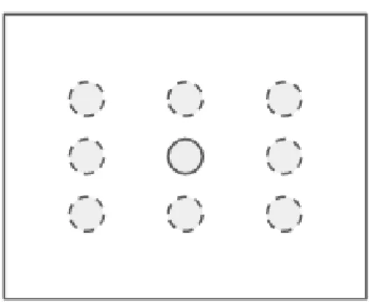
2-7 Example of how neighboring satellite images are chosen. The center dot with a solid border is the original center-point, where the dots with dotted line borders are 8 new centers for which satellite images will be fetched and attempted. . . 31
2-8 Matching similar UAV images . . . 33
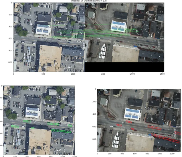
3-1 Example of “good” mapping of parking spots. . . 36
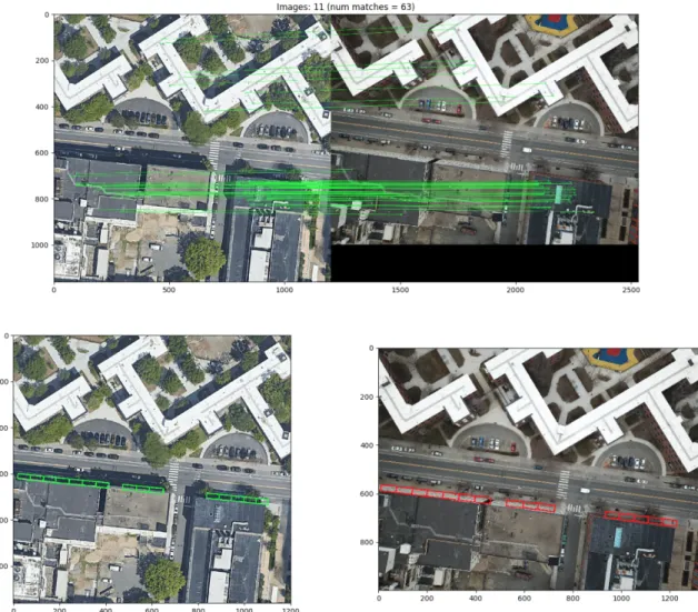
3-2 Example of “bad” mapping of parking spots. . . 36 3-3 Example of perspective differences betweens satellite and UAV imagery 39
Chapter 1
Introduction
Many applications, including mapping, infra monitoring, disaster relief, and remote sensing, use aerial imagery obtained from satellites or unmanned air vehicles (UAVs). Satellite imagery is the most frequently utilized aerial imagery in such applications, as the images are already aligned with GPS coordinates. As such, determining the GPS locations in a given satellite image is trivial. The tradeoff is that satellite imagery is not updated with the near real-time frequency required by many applications. The advent of inexpensive and easily deployable UAVs makes capturing up-to-date aerial imagery much more practical and cost effective, but solutions for performing high fidelity image registration in the captured imagery still do not exist. Aerial imagery captured by aircraft is difficult to align with global locations [13, 11]. Sensor noise in aircraft telemetry combined with imperfect camera modeling prevent accurate image registration in aerial imagery without additional information. As such, current solutions for image registration fall into two categories: hand-labeled correspondence, and marker-based solutions.
Implementors of hand-labeled solutions are forced to manually select correspon-dences between images in order to register the imagery. As such, hand-labeling is inefficient and does not scale because manual labeling is time-consuming and error-prone.
Marker-based solutions present their own challenges [11]. Markers in an image can provide relative accuracy for aerial imaging tasks, where only distances between
objects are required to be accurate. Absolute accuracy means that both the distances between objects are accurate – not distorted by the camera lens or elevation – and pixels in the images have known global locations (GPS). To achieve absolute accuracy, ground control points (GCPs) are used. In general, simple measurement applications require only relative accuracy, but larger scale applications and those requiring geo-referencing require absolute accuracy to extract value from the imaging. Using GCPs requires placing large markers throughout the area that will be imaged and perform-ing professional surveyperform-ing of the points in order to determine their precise global positions. These markers are designed to be easily recognized in the aerial imagery using pattern recognition. By identifying the markers, positions of other objects or locations of interest may be interpolated. Due to the monetary cost and inconve-nience of setting up GCPs, aerial imaging applications requiring absolute accuracy are limited in the size the area that can be imaged as well as the accuracy of image registration.
This thesis aims to alleviate the difficulties in performing accurate image regis-tration in aerial images captured by aircraft without high fidelity telemetry. The proposed solution utilizes existing satellite imagery to perform image feature detec-tion and matching between the satellite imagery and images captured by a UAV. Because the satellite imagery is already registered, registering the UAV imagery to it provides a global registration with GPS coordinates. By providing a simple and scal-able solution, UAVs can be used to image areas much more frequently than satellites while ensuring that the images can be accurately registered with location data and used in a variety of applications.
1.1
Related Work
1.1.1
Image Registration Overview
Image registration is defined as the process of transforming different sets of data into the image coordinate system. The data being transformed can be of any form,
Figure 1-1: Example of a GCP (left) and GCPs labeled in an aerial image (right) [4].
even other images. The task of registering two images is to align them into one image coordinate system. This is useful in constructing panoramas or more generally stitching multiple images together. In this thesis, image registration is used as a term for both the act of aligning two images as well as translating non-image data into an image’s coordinate system.
There are a plethora of methods to register images that vary with the kind of data one is registering. Many are described in detail in [15]. However, the requisites for aligning data to an image coordinate system are fundamentally the same in each: identifying points in the image that correspond to points in the data. This is normally accomplished in one of two ways.
Markers and Labeling
By manually pairing pixels in the imagery being registered with either corresponding data points or pixels (i.e. labeling them) in another image, we create a correspondence between the data and imagery. This manual process is common when registering images with maps, as placement and accurate measurement of markers (often referred to as Ground Control Points or GCPs) can be costly and time-intensive.
Markers or GCPs are used by first placing objects that are easily recognizable in the field prior to any image capture. These markers must have known locations. After
imagery has been collected, the markers are recognized in the imagery (manually or programmatically). Knowing both the pixel locations of the markers in the imagery and their locations in the world gives the desired matching registers the imagery. Examples of both a GCP and matched GCPs are shown in Figure 1-1.
Both the marker and manually labeling techniques can be applied generally to image-to-image registration as well as other forms of data. However, both suffer from being manual processes that take significant effort for larger amounts of data.
Surface Meshing
Surface meshing approaches to registration are similar in that they are techniques applied specifically to the task of registering two or more images. This can be done automatically with no manual labeling. Surface meshing focuses on using the contents of the respective images to help align their coordinate systems.
This process requires imagery taken from multiple camera angles and/or positions of overlapping scenes [3]. With aerial imagery, often images are taken in sequences with many of the images containing overlapping contents. Thus, this requirement is satisfied in most cases.
Using multiple images from different camera positions or angles, one can think of the collection of images as providing a stereo camera. Given multiple 2D images of the same object, a 3D representation can be calculated. Such techniques need to identify corresponding surfaces across the imagery in order to accurately mesh together the surfaces, and thus align the images.
Calculation from Aircraft Telemetry Data and Camera Characteristics To determine the GPS coordinates of a pixel in an image without external data, one must know precisely the location of the camera lens (thereby the aircraft), its orienta-tion, altitude, pitch, roll, yaw, field of view (FOV), and lens distortion characteristics [13]. Not only is each of these pieces of data difficult to acquire accurately, but small amounts of error in any one measurement will compound in the geometry cal-culation. Satellites, although flying both higher and faster, are equipped with much
higher precision sensors and communicate with multiple ground locations in order to accurately determine values for telemetry. Because consumer UAVs are subject to the relatively low accuracy of GPS approximately within 10m) and consumer-grade sensors, obtaining accurate telemetry can be nearly impossible.
Even still, the most accurate registration of satellite imagery is still achieved with the use of GCPs [11] to aid the process of georeferencing and the construction of orthoimages.
1.1.2
Image Feature Detection And Matching
The process of feature detection and matching between images involves identifying features in each image and matching those that correspond to the same feature be-tween them. Computing these features has been studied and implemented in methods like SURF and SIFT [2, 8]. Generally, implementations fall into two basic categories: keypoint -based, and area-based approaches.
Keypoints Keypoints, as described in [8], are points in an image deemed to be the location of a feature detected algorithmically. A keypoint is accompanied by a corresponding descriptor, which is the representation of the feature in a vector-space. Features of this sort are detected and described prior to a matching step, which involves searching for features present in separate images that correspond to one another based on their descriptors. An example of this is shown in Figure 1-2.
Area-Based Techniques termed “area-based“ have no preprocessing step in which features are detected in images separately [5]. These techniques jump straight to the matching step, in which algorithms search for matches between images based on areas within the images.
This thesis makes use of existing feature detection and matching algorithms be-longing to the keypoint variety, specifically SIFT [8]. SIFT terms features keypoints, and their corresponding representations descriptors. Matching these features between images has proven to be an effective method for registration [12, 15].
Figure 1-2: Feature detection example. An image (top) is processed and distinctive features are detected (bottom, shown in grayscale for easier viewing). Keypoints are shown as green circles in the right image, the diameter of the circles represents the size of the keypoint.
Figure 1-3: Feature matching example. Two sets of image features and descriptors (left) are matched and the matching is shown as linked pairs of feature points (right).
Matching image features between multiple images enables the construction of a transformation matrix (homography) between the images’ respective coordinate sys-tems. With the homography, one can transform any pixel location from one image to the other, thus the images are aligned into eachother’s coordinate systems. A vi-sual of matched features between two images can be seen in figure 1-3. Determining matchings between the features of two images is an active area of research, however the general approach is simple. Given features in the form of keypoints and descrip-tors, any number of algorithms can be employed for comparing the possible pairwise matches between images. The algorithms responsibility, however, is always to find the pairings that are most similar. This is done by comparing the descriptors as they represent the characteristics of the keypoints. There are numerous methods for determining matchings; in this thesis we use FLANN [10] to efficiently match key-points and the threshold on the Hamming distance of descriptors proposed in [8] for determining whether a match is of high fidelity.
1.1.3
Orthoimages
Orthoimages or ortho mosaic images are termed to be images correctly aligned to a map and normalized such that distances between pixels can be interpreted as physical distances undistorted by elevation differences and camera orientations. The process of constructing an orthoimage from a collection of aerial images is called orthorec-tification. Orhtoimages are often a desired output of aerial photography and are
Figure 1-4: Example of artifacts introduced by constructing an orthoimage using surface meshing (checkered pixels are empty).
produced by stitching together multiple aerial images using individual or combined methods involving GCPs and surface meshing. Many software packages and platforms produce orthoimages readily with or without GCP data such as OpenDroneMap, Pix4Dmapper, and more.
The accuracy of these images in terms of normalization and registration with a map depends greatly on the algorithmic ability to register the images to each other as well as a reference map. Registration with a map is done either with GCPs or by using geotagging information stored alongside images. Naturally, the use of GCPs aids both of these endeavors but can be impractical. Each of [7, 12, 14] discuss different techniques for increasing both the quality of the mosaic produced as well as map alignment. Specifically [12] uses a similar technique of registration of orthoimages with reference satellite imagery to produce a higher quality alignment.
In this thesis, I opt not to work with orthoimages, but instead with raw captured imagery out of the UAV. Because of the low operating altitude of consumer UAVs,
the construction of orthoimages can be difficult given the amount of perspective present in the imagery, especially in urban environments. This generally leads to large artifacts in the produces orthoimages as shown in figure 1-4, making them challenging to register with satellite imagery. Additionally, constructing orthoimages is computationally intensive, especially in the absence of hints from GCP data. I show that registering individual images from the UAV with satellite references can be an effective alternative, and can be used to generate GCP data to aid in the construction of orthoimages afterwards.
1.2
Summary of Contributions
This thesis presents a technique for the automatic registration of raw UAV images using feature detection and matching with satellite imagery. Our implementation enables registration with absolute accuracy without the use of markers like GCPs or hand-labeling.
We show that feature matching and detection can be used to register UAV im-ages that have not been orthorectified, tolerating lens distortion and differences in perspective from the reference satellite imagery. We also discuss ways in which the registration can fail, as well as additions to the pipeline to combat those failures. As a result, we are able to automatically register 65% of our test imagery accurately.
Chapter 2
Design and Implementation
In this chapter, we will outline the implementation of our solution. We will discuss our initial approach in order to explain the motivation for the subsequent implementation. Additionally, we will explain certain classes of failures and additions to the basic implementation that combat them.
2.1
Initial Approach
Our initial attempt at registering the UAV imagery used telemetry from the UAV to create an image coordinate system, as described in Section 1.1.1. Knowing the GPS location and altitude of the UAV at the moment an image was captured allows one to use the camera FOV and image resolution to determine the region visible in the image, and implicitly the geographic resolution.
This technique proved far too fickle for multiple reasons. First, the results obtained from this calculation are heavily influenced by any noise in the telemetry data from the UAV. Small changes in the GPS coordinate or altitude reading equated to errors equivalent to meters or tens of meters in the image coordinate system produced. Second, for simplicity the calculations assumed the UAV’s camera to be parallel to the ground. This assumption is reasonable given that our model of UAV uses a 3-axis gimble for stabilization, but even slight perturbations in the orientation of the camera equate to large errors in the coordinate system produced. As such, the determination
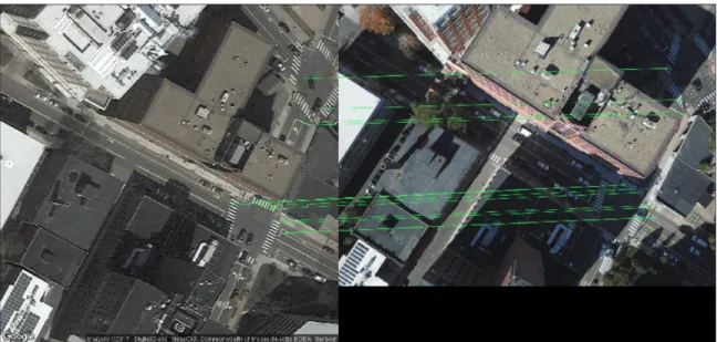
Figure 2-1: Example of feature matching between a satellite image (left) and UAV image (right) of the same area.
was made that in the absence of near-perfect telemetry data the task could not be completed without somehow utilizing the contents of the images.
2.2
Feature Detection and Matching Approach
Given the unreliable nature of UAV telemetry, using image feature detection and matching proved to be an effective alternative.
The core idea in our approach is to use already registered reference images con-taining the same or similar content to that of the UAV images. We build on the techniques described in [7, 12], as they also turned to feature detection and match-ing as a solution to registration. However, we work directly with raw UAV imagery as opposed to orthorectified imagery. For reference images, we use satellite imagery from Google at zoom level 19 (the highest). We found that this zoom level provided sufficiently similar image contents to that of the imagery captured with our UAV at the maximum flight altitude authorized by the FAA (120m).
Using the approximate GPS location of the UAV recorded with each image cap-ture, a corresponding satellite is selected, centered at this GPS coordinate. This satellite image is our reference. The pair of satellite and UAV image are processed
into features and matched as described in Section 1.1.2. An example matching be-tween a satellite reference image and a UAV image can be found in Figure 2-1. We then find matches between the detected features of the satellite and UAV images. The FLANNMatch step finds matches between the keypoints based on their descriptors – their vector representation as image features – using an augmented nearest-neighbors approach [10]. In the matching step, every descriptor is matched to another, but not all matched pairs are necessarily matches. Thus, we disqualify matches with a “distance” in the descriptor feature space higher than a threshold (0.7) as proposed in [8]. From the matched points, a homography – transform matrix – is computed to translate any pixel from the satellite image into the UAV image. Below is pseudo-code for the overall algorithm:
Algorithm 1 Calculate Homography 𝐻 between 𝑖𝑚𝑔1 and 𝑖𝑚𝑔2
𝑘𝑒𝑦𝑃 𝑜𝑖𝑛𝑡𝑠1, 𝑑𝑒𝑠𝑐𝑟𝑖𝑝𝑡𝑜𝑟𝑠1 ← 𝑠𝑖𝑓 𝑡.𝑑𝑒𝑡𝑒𝑐𝑡𝐴𝑛𝑑𝐶𝑜𝑚𝑝𝑢𝑡𝑒(𝑖𝑚𝑔1) 𝑘𝑒𝑦𝑃 𝑜𝑖𝑛𝑡𝑠2, 𝑑𝑒𝑠𝑐𝑟𝑖𝑝𝑡𝑜𝑟𝑠2 ← 𝑠𝑖𝑓 𝑡.𝑑𝑒𝑡𝑒𝑐𝑡𝐴𝑛𝑑𝐶𝑜𝑚𝑝𝑢𝑡𝑒(𝑖𝑚𝑔2) 𝑚𝑎𝑡𝑐ℎ𝑒𝑠 ← 𝐹 𝐿𝐴𝑁 𝑁 𝑀 𝑎𝑡𝑐ℎ(𝑑𝑒𝑠𝑐𝑟𝑖𝑝𝑡𝑜𝑟𝑠1, 𝑑𝑒𝑠𝑐𝑟𝑖𝑝𝑡𝑜𝑟𝑠2) 𝑠𝑟𝑐𝑃 𝑜𝑖𝑛𝑡𝑠 ← [ ] 𝑑𝑠𝑡𝑃 𝑜𝑖𝑛𝑡𝑠 ← [ ] for 𝑚 ∈ 𝑚𝑎𝑡𝑐ℎ𝑒𝑠 do
// perform Lowe’s ratio test [8] if 𝑚.𝑑𝑖𝑠𝑡𝑎𝑛𝑐𝑒 ≤ 0.7 then 𝑠𝑟𝑐𝑃 𝑜𝑖𝑛𝑡𝑠.𝑎𝑝𝑝𝑒𝑛𝑑(𝑚.𝑠𝑟𝑐) 𝑑𝑠𝑡𝑃 𝑜𝑖𝑛𝑡𝑠.𝑎𝑝𝑝𝑒𝑛𝑑(𝑚.𝑑𝑠𝑡) end if end for 𝐻 = 𝑐𝑜𝑚𝑝𝑢𝑡𝑒𝐻𝑜𝑚𝑜𝑔𝑟𝑎𝑝ℎ𝑦(𝑠𝑟𝑐𝑃 𝑜𝑖𝑛𝑡𝑠, 𝑑𝑠𝑡𝑃 𝑜𝑖𝑛𝑡𝑠) return 𝐻
Computing the homography is a simple process of computing a linear function mapping coordinates in one image into another. A comprehensive explanation can be found in [1], but we will provide a summary of the process.
Since our points are 2D and the images are offset from each other, the perspective transform will require a 3x3 homography matrix 𝐻. This requires a minimum of 4 pairs of points, no 3 of which are collinear so as to ensure there are enough equations to solve for the entries of 𝐻. To incorporate the offset in the calculation, one transforms points as 𝑥𝑖 = (𝑥𝑖, 𝑦𝑖) → 𝑥𝑖 = (𝑥𝑖, 𝑦𝑖, 1).
Let’s denote a pair 𝑖 by 𝑥𝑖 ↔ 𝑥′𝑖. By computing a homography, we compute the
matrix 𝐻 such that 𝑥′𝑖 = 𝐻𝑥𝑖. Noting that 𝑥′𝑖 does not necessarily equal 𝐻𝑥𝑖, but
they are in the same direction, we know that 𝑥′𝑖× 𝐻𝑥𝑖 = 0. This cross product gives
us a system of equations to solve. Writing 𝑥𝑖 = (𝑥𝑖, 𝑦𝑖, 1) and the 𝑗𝑡ℎ row of 𝐻 as ℎ𝑗,
the equation to solve for a given pair is as follows:
𝑥′𝑖× 𝐻𝑥𝑖 = ⎛ ⎜ ⎜ ⎜ ⎝ 𝑦𝑖′ℎ3𝑇 𝑥𝑖𝑔 − ℎ2 𝑇 𝑥𝑖 ℎ1𝑇𝑥 𝑖𝑔 − 𝑥𝑖ℎ3 𝑇 𝑥𝑖 𝑥′𝑖ℎ3𝑇 𝑥𝑖𝑔 − 𝑦′𝑖ℎ2 𝑇 𝑥𝑖 ⎞ ⎟ ⎟ ⎟ ⎠ (2.1) Because ℎ𝑗𝑇
𝑥𝑖 = 𝑥𝑇𝑖 ℎ𝑗, we can rearrange so all the unknowns are separated:
𝑥′𝑖× 𝐻𝑥𝑖 = ⎛ ⎜ ⎜ ⎜ ⎝ 0𝑇 −𝑥𝑇 𝑖 𝑦 ′ 𝑖𝑥𝑇𝑖 𝑥𝑇𝑖 0𝑇 −𝑥′ 𝑖𝑥𝑇𝑖 −𝑦𝑇 𝑖 𝑥 ′ 𝑖𝑥𝑇𝑖 0𝑇 ⎞ ⎟ ⎟ ⎟ ⎠ ⎛ ⎜ ⎜ ⎜ ⎝ ℎ1 ℎ2 ℎ3 ⎞ ⎟ ⎟ ⎟ ⎠ = 𝐴𝑖ℎ = 0 (2.2)
The formula 𝐴𝑖ℎ = 0 includes 𝐴𝑖 which is a 3x9 matrix, and ℎ which is 9x1
corresponding to the entries of 𝐻. By stacking at least four such 𝐴𝑖’s, we obtain a
formula 𝐴ℎ = 0 where 𝐴 is a 12x9 matrix with a 1-dimensional null space (given that no three of the four points are collinear), leaving the system solvable. Using more than 4 correspondence pairs results in an over-determined system, which may or may not have an explicit solution to 𝐴ℎ = 0. In this case, we find the solution that minimizes ||𝐴ℎ||.
The computed homography is a matrix 𝐻, which is used to project points from one image to the other via matrix multiplication. This projection translates pixels, so any data we project must first be translated into pixels in one of the images.
For this thesis, we use an implementation of the homography calculation provided in getPerspectiveTransform(...) from OpenCV.
Because the reference satellite image has a known GPS coordinate system, any GPS data can be transformed into the satellite image’s pixel coordinate system, and
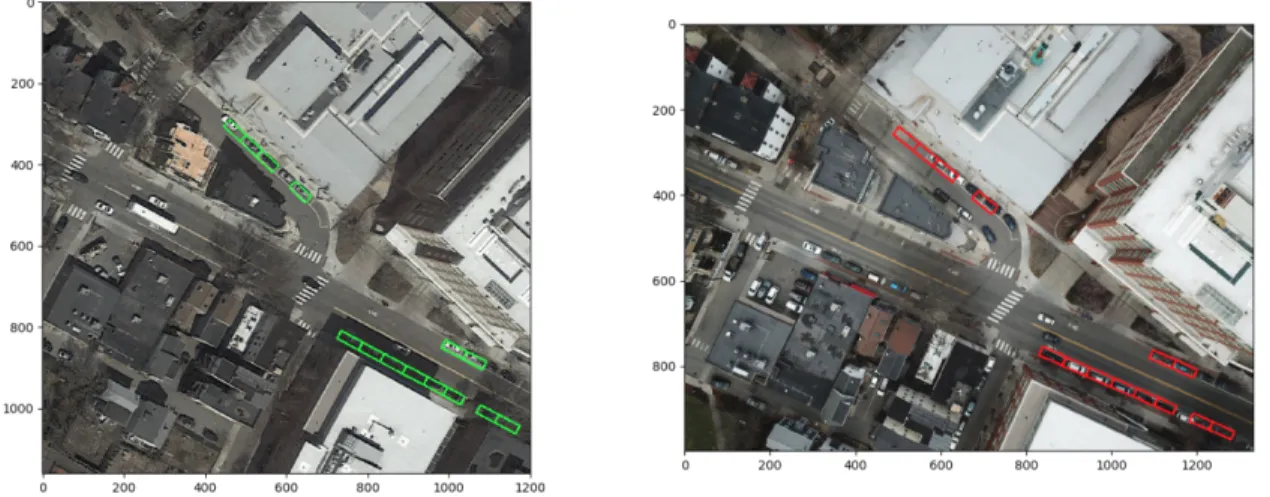
Figure 2-2: Mapping location data from satellite (left) to UAV image (right)
subsequently transformed into the UAV image’s pixel coordinate system using the homography found from previous step. An example result showing the mapping of GPS coordinates of parking spot bounding boxes is provided in Figure 2-2.
A visualization of the entire pipeline is shown in Figure 2-3.
2.3
Robustness and Extensions
We observe success in applying the matching pipeline described above. However, there are several cases where either the matching fails or generates inaccurate homographies.
2.3.1
Failures
Failed Matchings
The most common way a matching can fail is illustrated in Figure 2-4. This failure occurs when more than one of the keypoints in the reference satellite image match to the same keypoints in the UAV image. This seems to occur somewhat at ran-dom in certain images, but also occurs when the images are difficult to match (i.e. inconsistent contents).
Figure 2-3: (a) A satellite image corresponding to the center-point of UAV image (b). (c) The detected feature matching between images (a) and (b). (d) Image (a) with GPS parking spot bounds overlayed. (e) The same parking spots mapped into (b) using the homography computed from (c).
Figure 2-4: Failed image feature matching
Low Quality Matchings
The next most common failure in the pipeline is simply a low quality matching be-tween the satellite and UAV imagery. This failure is most commonly observed in two cases: when matched keypoints are very densely packed, or matches are entirely on rooftops.
Dense Packing Densely packed points are problematic for image registration in this case because of the non-uniform perspective in the UAV imagery. An example of this failure is shown in Figure 2-5. As it has not been normalized like an orthoimage, the UAV imagery is impacted by perspective and lens distortion. This means that computed homographies are most valid for points near the matched keypoints, and the quality degrades as the data gets farther away. Naturally, it follows that if the matched keypoints are densely packed in one area of the image, the homography will not properly transform data in other areas.
Predominantly Rooftop Matching Similar to the problem of densely packed matchings, homograhies comprised mostly or solely of matches on buildings and specifically rooftops suffer. An example of this is shown in Figure 2-6. Again, since
Figure 2-5: Example of low quality matching occurring as a result of matched points being densely packed.
Figure 2-6: Example of low quality matching occurring as a result of matched points being only on rooftops.
the UAV images are not normalized, perspective distortion yields transformations that are vary throughout the image. As a result, if a homography is computed based on mostly matches on rooftops, the homography will not accurately transform points on the ground or other altitudes.
2.3.2
Solutions to Failures
Failed Matchings
To combat failures resulting from non-unique keypoint pairs, we implemented the following procedure. After computing a matching between the reference image and UAV image, we look at the number of unique keypoints in the UAV image that were matched to similar ones in the reference image. By looking at the number of unique points matched as opposed to the overall number of matches, we can determine if many keypoints from one image are matching to fewer points in the other image. By thresholding on the number of uniquely matched keypoints, we can disqualify matchings with too few unique points.
To attempt correction of a matching with too few unique points, we use the follow-ing simple process. Due to the non-deterministic nature of computfollow-ing the matchfollow-ing via FLANN, recomputing a matching given the same keypoints and descriptors will not necessarily yield the same result. As such, the proposed protocol is as follows: given a matching with fewer than 10 unique keypoints in the UAV image matched, we recompute the matching up to 5 times, stopping if we yield a matching with more than 10 unique points. Through experimentation, we found that 10 was often the minimum number of unique keypoints required for a quality homography to be com-puted, although it does not guarantee it. In general, this process can correct many failures that occur due to randomness from FLANN. However, matchings that fail due to the difficulty of matching a particular pair will repeatedly fail and be flagged in the pipeline as failed. Procedures described below for correcting low quality matchings can be applied to correct these failed matchings.
Figure 2-7: Example of how neighboring satellite images are chosen. The center dot with a solid border is the original center-point, where the dots with dotted line borders are 8 new centers for which satellite images will be fetched and attempted.
Low Quality Matchings
To combat the issues in low quality matchings, we implemented two methods and evaluated them qualitatively.
Method 1: Matching Neighboring Satellite Images Given the likelihood of noise in the drone’s GPS reading at the time of image capture, it is reasonable to assume that the reference satellite image may not be well suited to matching the contents of the UAV image. For the matching to succeed, the images must have similar contents.
Thus, a step is added to the pipeline. Given matchings that are deemed unsuc-cessful, we attempt the matching with new satellite images near to the original. From the original center point, we select 8 new center-points near the GPS coordinate of the original. An example of how the new center-points are chosen is shown in Figure 2-7. Through experimentation, we found it reasonable to use center-points roughly 25-75 meters away from the original. From the newly chosen center-points, new satellite images are fetched and matchings are attempted with each of the new satellite images
and the original UAV image.
Through experimentation, it was determined that this extension does not reliably improve the quality of matching. Barring significant GPS noise, using satellite images centered farther from the UAV’s location reduces the overlapping content in the pairs of images. Thus, matching nearby satellite imagery implicitly restricts the potential features that can be matched to more limited regions in the UAV image. Because the homographies are most accurate near the features used to compute them, this approach generally limits the potential quality of the homography over the entire UAV image.
As a result, this approach is most useful in the presence of significant GPS noise. If the contents of the original images are divergent to begin with, this can prove a helpful addition.
Method 2: Projection Through Neighboring UAV Images Another alterna-tive approach to registering images with failed matchings is to utilize neighboring or nearby matchings that were successful. UAV imagery is most often taken in sequences of images, and adjacent images often have significant amounts of content in common (this is required for the construction of orthoimages). As shown in Figure 2-8, using feature detection and matching to register UAV images with similar content yields high quality homographies as many features are easily matched between the images. We will explain how to apply the technique in a simple case and then the general case.
Failed Image Adjacent to a Successfully Matched Image Given that a failed matching occurs with a UAV image adjacent to another image that succeeded, applying the neighbor projection technique is very simple. First, we compute a ho-mography between the UAV image that succeeded and the one that failed using the same feature detection approach described previously. Call this homography 𝐺. Sec-ond, we recover the original homography generated by the pipeline for the successful UAV image (𝐻), and it’s corresponding satellite reference image. In order to project
Figure 2-8: Matching similar UAV images
data into the failed UAV image, we can simply multiply the two homographies: the first being the original between the reference satellite image and successful UAV im-age, the second being the newly computed homography between the successful UAV image and failed UAV image. This computes 𝐻𝑐𝑜𝑚𝑏𝑖𝑛𝑒𝑑 as shown below.
𝐻𝑐𝑜𝑚𝑏𝑖𝑛𝑒𝑑= 𝐻𝐺
By multiplying these homographies together, the effect is computing an overall homography between the reference satellite image and the failed UAV image. Using this combined homography, data can be transformed into the original reference satel-lite image’s coordinate system and subsequently projected directly into that of the failed UAV image.
Failed Image Anywhere in a Sequence Now, given a UAV image for which the matching pipeline failed anywhere in a sequence (not necessarily adjacent to a successful matching), the process for applying this technique is only slightly different. First, we find it’s nearest neighboring UAV image for which the pipeline succeeded in finding a reliable homography, 𝐻. Given the nearest successful image, we can compute homographies between each UAV image in the sequence between the successful image found and the failed image we seek to fix. Call these homographies 𝐺𝑖𝑗, where 𝑖 and 𝑗
image, and the last such 𝑗 is the image we are fixing. To compute the combined homography, we simply multiply them together in order as shown below.
𝐻𝑐𝑜𝑚𝑏𝑖𝑛𝑒𝑑= 𝐻
∏︁
𝑖,𝑗
𝐺𝑖𝑗
Once this combined homography for transforming from the successful image to the failed image is computed, we can again simply translate data into the original reference satellite image’s pixel coordinate system and use 𝐻𝑐𝑜𝑚𝑏𝑖𝑛𝑒𝑑to project directly
into the failed UAV image.
Effectiveness Projection through neighboring images proves generally unsuc-cessful due to the same limitations as previously described methods. Because the sequential UAV images contain physically separated content, even high quality match-ings in a successful image degrade when projected into neighboring images using the combined homographies. This is again a result of non-uniform perspective or the UAV imagery, as well as the lack of proximity between the matched features and projected coordinates.
Chapter 3
Evaluation and Discussion
In this chapter I will evaluate the implementation presented in order to show its effectiveness. Additionally, I will discuss its shortcomings and elaborate on their causes.
3.1
Evaluation
In order to evaluate the methods presented, I captured approximately 200 images near the MIT campus and surrounding area with a DJI Mavic Pro. I used Google satellite images as reference imagery, and data from the city of Cambridge to project into our imagery. The data I chose contains the locations and boundaries of metered parking spaces from the CambridgeGIS repository 1. The parking spaces are easily
visualized, and the bounding boxes by definition create a spatial relationship between points, making it easy to detect errors in the registration.
To assess accuracy of the registration at a pixel level programmitcally, we would need a dataset with ground truth labels on the UAV imagery. Such datasets were not discovered in our search, specifically imagery taken at roughly the right altitude (120m) and approximately north-facing.
Due to this lack of such data applicable to our methods, I opted for a different evaluation. I assess overall success of the registration of a particular image visually
Figure 3-1: Example of “good” mapping of parking spots.
in a binary fashion. Examples of both a successful and unsuccessful matching are provided in Figures 3-1 and 3-2. The goal of visual inspection is to assert that the homography for a given image accurately registers the boundaries of the parking spaces within approximately 1-2m of error. I classify an image as unsuccessfully matched if any of the parking spaces visible in the image are poorly mapped by the computed homography. This results in fairly stringent requirements for a successful matching, yet the presented method still yields promising results.
Using the un-extended approach presented in Section 2.2 along with the repeated attempts at matching described in Section 2.3.2, 58.52% of images were successfully registered given the aforementioned criteria. Incorporating the extensions outlined in Section 2.3.2 yielded mixed results. Using neighboring UAV images (Method 2) to correct unsuccessful matchings did not improve performance, however, using the technique of matching nearby satellite images (Method 1) increased the percent of successful matchings to 65.34%.
This result is indicates to us that image registration using our proposed approach is viable, although not able to be applied in totally automatic setting. If used alongside human correction, we believe this approach can be used to significantly increase the efficiency of data collection for aerial imaging applications.
3.2
Discussion
3.2.1
Reliance on Reference Imagery
The proposed approach to UAV image registration relies heavily on the presence existing registered imagery as reference. This is consistent with other state-of-the-art approaches to automatic image registration, however, it is a potential limitation in this method’s application. Google provides free access to fairly up-to-date satellite imagery, which is a good source of reference imagery and has good global coverage. As such, general use of this image registration technique should be possible.
3.2.2
Feature Matching Difficulty and Observations
As discussed in section 2.3.1, the proposed technique has limitations which are dif-ficult to avoid. By nature, unprocessed UAV imagery suffers from perspective and camera lens distortions, and these distortions negatively impact the effective radius of even high quality homographies found between reference and UAV imagery. As such, densely packaged feature matchings produce homographies that have minimal effectiveness.
The more challenging issue to combat is when matched features don’t belong to the ground plane in the imagery. Rooftops are very prominent in satellite and even more so in UAV imagery due to the difference in capture altitude. Matchings constructed from predominantly rooftop keypoints struggle greatly in projecting GPS data on the ground plane. At this time, it is unclear how to solve this issue in general without significant human intervention or incorporating object recognition into the pipeline.
This is an area where the use of orthoimages can provide better results. Because of the normalization and map correction, orthoimages contain uniform perspective throughout the image area, and are less susceptible to these forms of distortion.
3.2.3
Scale Invariance and Satellite vs UAV Perspective
In order to handle any scaling differences in UAV and satellite imagery, we rely on the implementation of the feature detection algorithms. Most feature detection algo-rithms advertise scale-invariance. SURF and SIFT are two examples [2, 8], but there are numerous others including but not limited to BRIEF, BRISK, and ORB. This is important in contexts where very tall buildings are found. Due to the significant difference in capture altitude, a tall building appears much larger in UAV imagery. As a result, features on rooftops appear at different scales. In experiments, this seems to be a non-issue for our test area in Cambridge, MA, however I believe it may be more challenging in areas with buildings taller than those we encountered.
Dealing with perspective differences between the UAV and satellite imagery does however present interesting challenges not solved by constructing orthoimages.
Satel-Figure 3-3: Example of perspective differences betweens satellite and UAV imagery
lite imagery provided by Google is not the same as a standard orthoimage. The imagery is map-aligned, meaning distances in the image can be treated roughly as absolute distances in the world, however, all perspective from the image capture has not been removed. The UAV, flying at such low altitude, sees buildings and other large 3-dimensional objects with substantially different perspectives in different im-ages in a flight sequence. In general, satellite imagery observes the world from a consistent perspective, especially at high zoom levels. As such many faces of build-ings visible in UAV images are not visible in the satellite imagery and often certain regions of the ground are occluded by buildings viewed from the satellite perspective. An example of these differences can be found in figure 3-3.
These dissimilarities adversely affect matchings as they limit the number of pos-sible features that the sources of imagery could possibly have in common. Occlusions can be particularly challenging to deal with. The example in figure 3-3 shows one such occlusion of a portion of an intersection. In circumstances where the goal of registration is to be able to place ground level data in the UAV image, homographies calculated between images with this type of occlusion will likely be inaccurate in the areas of the UAV imagery occluded in the satellite imagery. This is potentially a fundamental limitation of using imagery at this zoom level.
Chapter 4
Conclusion
In this chapter I will conclude by summarizing the work presented and explaining possible next steps in extending this research.
4.1
Conclusion
In this thesis, I presented an approach for the automatic registration of raw UAV imagery using feature detection and matching with reference satellite imagery. I first defined motivations for the work and challenges associated with the task of image reg-istration, and subsequently implemented a solution. I then discussed different classes of failures observed with the implemented pipeline and extensions to combat them. Lastly, I evaluated the solutions and their effectiveness on a constructed dataset.
4.2
Future Work
Given the shortcomings observed with the presented approaches, a reasonable next step would be to continue to evaluate different avenues for improving the results. One potential improvement may involve integration with existing research, such as programatically generating the manually labeled correspondence points for use in [7] or incorporating hints for registration from [12].
predom-inantly qualitatively. A reasonable next step would be to acquire or create a ground truth dataset to empirically evaluate the various techniques presented in order to determine precisely the efficacy of different approaches.
In addition to a strictly deeper evaluation, I believe testing this approach in dif-ferent environments would be illustrative. Cambridge Massachusetts is small region that is predominantly urban with recently updated satellite imagery. Even recent con-struction projects near the MIT campus were visible in Google’s imagery. As such, it would be interesting to evaluate these approaches against less up-to-date satellite imagery, as I would expect that to be the norm in less populated or less urbanized areas of the globe.
Another avenue worth exploring is the use of object detection within aerial im-ages in order to identify high level features such as buildings or intersections that could be used to georeference imagery. Features detected by algorithms such as SIFT tend to be low level features about shapes and distinguishable patterns within pixels. With modern computer vision techniques, higher level objects can be localized reli-ably in images, such as buildings, roads, or trees. Research has been conducted on generalizable image segmentation for aerial imagery [9, 6], but this would be a novel application for use in georeferencing.
4.3
Contributions
In this thesis, we present a method for automatically registering raw UAV imagery without orthorectification, the use of markers, or hand-labeling. Our proposed tech-nique shows that image feature detection and matching can be applied to accurately register UAV imagery in place of other, less-scalable methods.
We also discuss sources of errors in the image registration pipeline, and propose extensions to the presented method that increase its reliability. Finally, we evaluate our technique against a dataset of images and showed that it successfully registered approximately 65% of our UAV imagery. Overall, the approach is limited in its success as a fully-automated method, but it shows promise as a tool to be used to produce
Bibliography
[1] Subhashis Banerjee. How to compute a homography. http://www.cse.iitd.ernet.in/ suban/vision/geometry/node24.html. Accessed: 2018-05-18.
[2] Herbert Bay, Tinne Tuytelaars, and Luc Van Gool. Surf: Speeded up robust features. 2006.
[3] Liang Cheng, Gong Jianya, Li Manchun, and Yongxue Liu. 3d building model reconstruction from multi-view aerial imagery and lidar data. 77:125–139, 02 2011.
[4] Drone Deploy. Creating quality gcps for mapping contour lines. https://www.groundcontrolpoints.com/mapping-contour-lines-using-gcps/. Ac-cessed: 2018-05-22.
[5] Jyoti Joglekar and Shirish Gedam. Area based image matching methods-a survey. 2:130–136, 01 2012.
[6] Franz Leberl, Horst Bischof, Helmut Grabner, and Stefan Kluckner. Recognizing cars in aerial imagery to improve orthophotos. Technical report, Institute for Computer Graphics and Vision, Graz University of Technology, 2007.
[7] Yuping Lin and Gerard G. Medioni. Map-enhanced uav image sequence regis-tration and synchronization of multiple image sequences. June 2007.
[8] David G. Lowe. Distinctive image features from scale-invariant keypoints. In-ternational Journal of Computer Vision, 2004.
[9] Volodymyr Mnih. Machine Learning for Aerial Image Labeling. PhD thesis, University of Toronto, 2013.
[10] Marius Muja and David Lowe. Fast approximate nearest neighbors with auto-matic algorithm configuration. 1:331–340, 01 2009.
[11] Th Toutin and R Chnier. Gcp requirement for high-resolution satellite mapping. 35, 01 2004.
[12] Chung-Hsien Tsai and Yu-Ching Lin. An accelerated image matching technique for uav orthoimage registration. volume 128, pages 130–145, 2017.
[13] Meng-Lun Tsai, Kai-Wei Chiang, Jiann-Yeou Rau, and Yun-Wen Huang. The performance analysis of a uav based mobile mapping system platform. volume XL-1/W2, 2013.
[14] Mohamed Zahran. Towards generating accurate orthoimages for urban areas. Journal of Engineering and Applied Science, October 2009.
[15] Barbara Zitov and Jan Flusser. Image registration methods: A survey. 21:977– 1000, 10 2003.
![Figure 1-1: Example of a GCP (left) and GCPs labeled in an aerial image (right) [4].](https://thumb-eu.123doks.com/thumbv2/123doknet/14134069.469451/13.918.144.762.106.406/figure-example-gcp-gcps-labeled-aerial-image-right.webp)