Publisher’s version / Version de l'éditeur:
Technical Note (National Research Council of Canada. Division of Building Research), 1967-06-01
READ THESE TERMS AND CONDITIONS CAREFULLY BEFORE USING THIS WEBSITE.
https://nrc-publications.canada.ca/eng/copyright
Vous avez des questions? Nous pouvons vous aider. Pour communiquer directement avec un auteur, consultez la
première page de la revue dans laquelle son article a été publié afin de trouver ses coordonnées. Si vous n’arrivez pas à les repérer, communiquez avec nous à [email protected].
Questions? Contact the NRC Publications Archive team at
[email protected]. If you wish to email the authors directly, please see the first page of the publication for their contact information.
NRC Publications Archive
Archives des publications du CNRC
For the publisher’s version, please access the DOI link below./ Pour consulter la version de l’éditeur, utilisez le lien DOI ci-dessous.
https://doi.org/10.4224/20358924
Access and use of this website and the material on it are subject to the Terms and Conditions set forth at
Maximum Spans for Roof Trusses
Hansen, A. T.
https://publications-cnrc.canada.ca/fra/droits
L’accès à ce site Web et l’utilisation de son contenu sont assujettis aux conditions présentées dans le site LISEZ CES CONDITIONS ATTENTIVEMENT AVANT D’UTILISER CE SITE WEB.
NRC Publications Record / Notice d'Archives des publications de CNRC: https://nrc-publications.canada.ca/eng/view/object/?id=0a1c1a89-f047-46e3-848b-8c04cdf6daa9 https://publications-cnrc.canada.ca/fra/voir/objet/?id=0a1c1a89-f047-46e3-848b-8c04cdf6daa9
NATIONAL RESEARCH COUNCIL OF CANADA
DIVISION OF BUIL.DING RESEARCH
'f
EClHIN lICAlL
NOTlE
LIMITED DISTRIBUTION
No.
490
PREPARED BY A.T. Hansen CHECKED BY H.B.D. APPROVED BY N.B.H.
June 1967
PREPARED FOR limited distribution
SUBJECT MAXIMUM SPANS FOR ROOF TRUSSES
For the past several years the adequacy of residen-tial roof truss design in Canada has been determined by tests on full-size trusses. The criteria for acceptable performance have been that such trusses be able to support the design
ceiling load (10 psf) and 2 2/3 the design roof load for 24 hours. In addition, the deflection must not exceed 1/360 of the span when the trusses support the ceiling load plus 1 1/3 the design roof snow load for 1 hour (1). The design roof load is calculated at 60 per cent of the 20-year maximum ground snow load.
This system of assessing the adequacy of trusses has served the valuable purpose of permitting the rapid acceptance of many lightweight truss designs. Such tests are fairly expensive, however, and the large number of tests that have been undertaken over the years represents a sub-stantial amount of money. Sufficient experience has now
been obtained to reduce the necessity for many of these tests. If the characteristics of the connectors and the truss members are known i t should be possible to design the trusses to meet established criteria. As changes in standard lumber sizes are proposed for the near future, it is increasingly important to develop an acceptable design method to reduce the neces-sity for repeating a large number of loading tests to accom-modate the newer lumber sizes.
2
-The strength and deflection characteristics of a truss are influenced by the size and species of wood used for the members as well as the strength and slip characteristics 'of the connector plates. Knowing these factors, one should
be able to design a particular truss geometry to meet given performance criteria.
DEFLECTION
The deflection of a simple can be determined by the formulae:
2
[
Cl C2wL
(Fink) セ
=
1.3 E"w"
(Fink) or Howe truss(Howe) セ
=
Where セ
=
deflection (in.)w
=
total load (ceiling + roof) in Ib perl i n e a l f t of truss I
L
=
span (ft)E
=
modulus of elasticity under axial loading (psi) (1,500,000 for spruce)d
=
displacement of the plate relative to the wood at the loading being consideredC
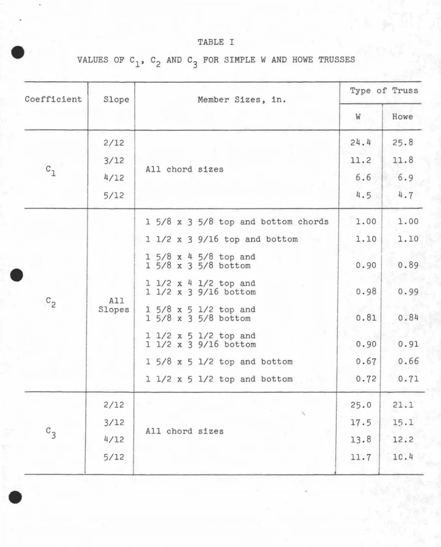
l , C2 and cセ are constants depending on slope, member SIze and type of truss (Table I). By equating these formulae to 1/360 of the span it is possible to determine the maximum spans that will meet the accepted deflection limit.
If a plate-connected joint is tested in a tensile testing machine under a slowly applied load and instrumented with dial gauges, information on the slip characteristics of the plate can be determined so that a curve showing the
relation of the plate slip relative to the, wood can be plotted for various load/tooth (or load/sq in. of plate) combinations. The slip of the plate, relative to the wood, varies with the design of the plate, but should normally be between 0.005 in.
3
-and 0.015 in. for a truss load equal to 1 1/3 the design roof load plus the ceiling load. Inmost cases of nailed trusses tested at DBR/NRC (2) this value was about 0.006 in. (3). If the slip characteristics of the plate over a given range of loads are known, it is possible to assign a design value to the plates to ensure that truss deflections will be within prescribed limits.
FAILURE LOAD
In addition to establishing the deflection character-istics of connector plates it is of equal importance to know their strength characteristics. If the truss is to carry a load of 2 2/3 the design roof load plus the ceiling load for 24 hours, the plate should have a failure load of about 3 1/3, or preferably 3 1/2 times the design load under a short-term joint test. When plates have marked differences in perfor-mance, resulting from orientation of the teeth to the direction of loading and wood grain, the plate should be tested for these conditions to ensure that the design value for the plate will be adequate for all joints.
In addition to providing adequate connector strength, the truss should have members of sufficient size to support the required test loading for 24 hours without failure.
In tests at DBR/NRC one truss design that just met the requirement for sustaining the ceiling load and 2 2/3 the design roof load for 24 hours was a 28-ft span, 4/12 slope
"w"
truss with 1 5/8 by 3 5/8 in. members throughout, loaded with a 10 psf ceiling load and 100 psf roof load. The dead load was assumed to be 5 psf. The truss was made of No. 1 spruce.The combined stresses due to axial loads and bending loads for the truss at this loading were calculated assuming pin-connected joints.
The maximum axial stress (psi) was determined from the formula
L
Sa
=
2hawhere L = span (in.)
h
=
ht of truss at peak (in.)w
=
1
4
-w
=
load on top chord (lb/lineal in.) including 1 dead loadw2
=
load on bottom chord (lb/lineal in.).The maximum bending stress (psi) was calculated from the formula
where L
=
span (in.)load on top chord (lb/lineal in.)
S
=
section modulus of the top chord (in. 3 ).For the simple Howe truss the bending stress can be calculated by the same formula as for the "W" truss, but the maximum axial stress is found from the formula
By equating Sa + Sb to the maximum combined stress calculated for the limiting truss previously mentioned, the maximum spans can be calculated for different geometries,
member sizes, and design loads for No.1 spruce or equivalent. RESULTS
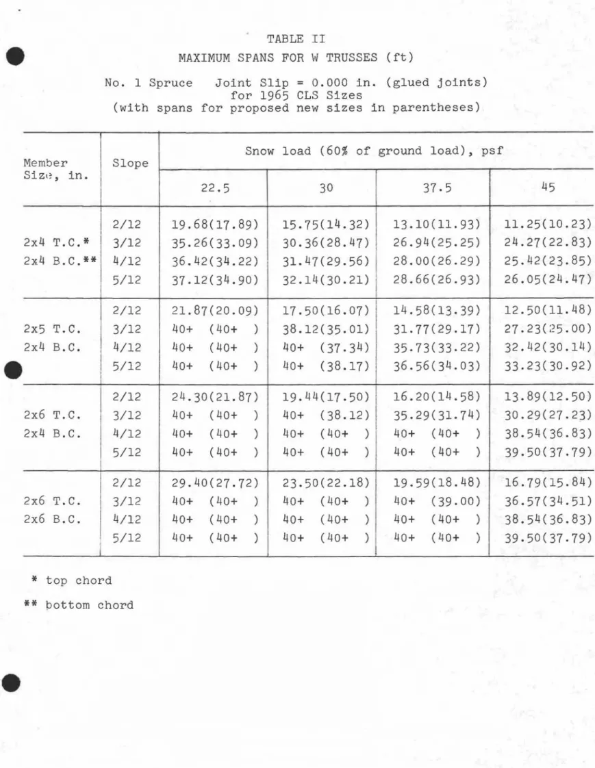
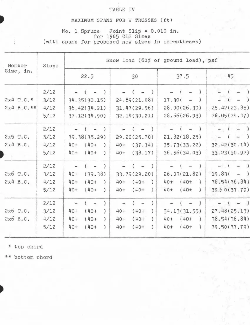
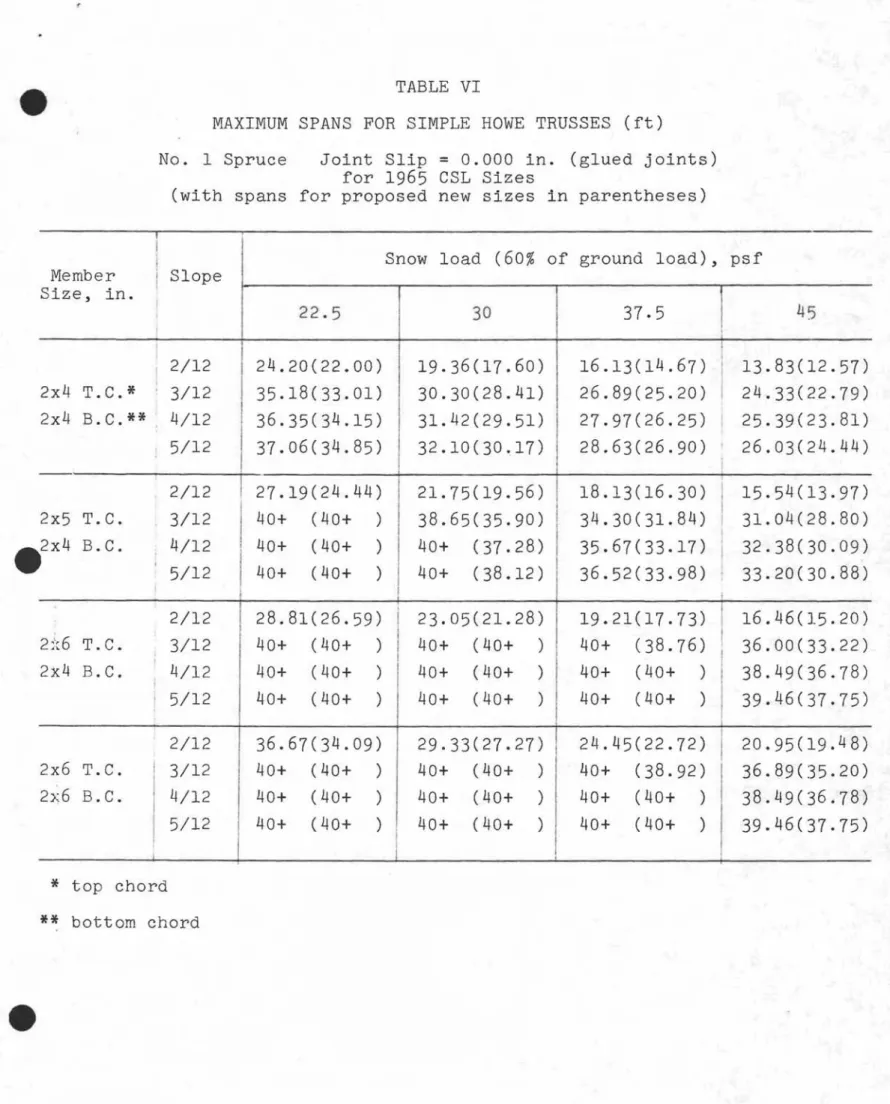
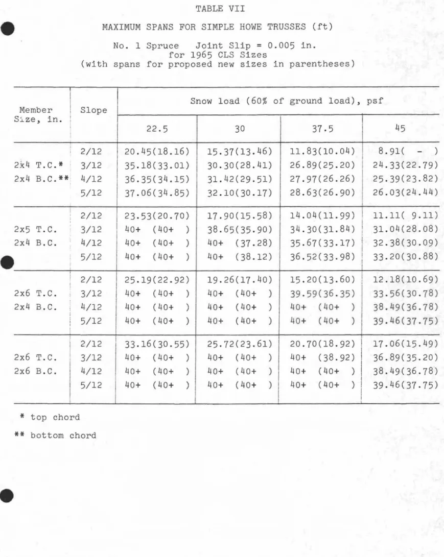
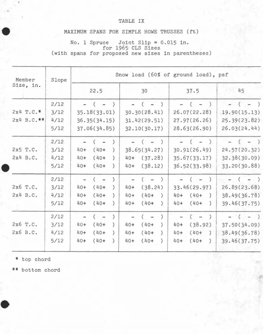
The maximum spans for simple "W" and Howe trusses were calculated for slopes of 2/12 to 5/12, with different combinations of member sizes and design roof loads, assuming connector displacements of from 0.000 in. to 0.015 in. at a load equal to the ceiling load plus 1 1/3 the design roof load. These calculations were done in relation to both deflection and strength. The limiting span in each case was taken as the
smaller span determined by the two conditions. These are summarized in Tables II to IX. The maximum spans in the tables are shown up to 40 ft, which is assumed to be the practical maximum span for residential roof trusses.
Deflection was the governing limitation in all 2/12 slope trusses and in many of the 3/12 slope trusses. In many cases it was not possible to list any span because of exces-sive deflections. The spans in Table II to IX are for the 1965 CSL sizes. The spans resulting in a reduction in lumber size under consideration by the CSA Softwood Lumber Committee
5
-are also included in these tables and -are shown in p-arentheses. REFERENCES
(1) Load Test Procedure for Wood Roof Trusses for Houses. National Research Council of Canada, Division of
BUilding Research, Technical Note No. 423. July 1964.
(2 ) Hansen, A.T. on Simple Symposium England.
Deflections of Wooden Roof Trusses Based Joint Tests. Presented at the International on Joints in Timber Structures, London,
March 1965.
(3) Hansen, A.T. Trussed Rafters for Houses. National Research Council of Canada, Division of Building Research, Ottawa. September 1963. NRC 7532.
TABLE I VALUES OF C
1, C2 AND C3 FOR SIMPLE W AND HOWE TRUSSES
Type of Truss
Coefficient Slope Member Sizes, in.
W Howe
2/12 24.4 25.8
3/12 11. 2 11. 8
C1 All chord sizes
4/12 6.6 6.9
5/12 4.5 4.7
1 5/8 x 3 5/8 top and bottom chords 1. 00 1. 00
1 1/2 x 3 9/16 top and bottom 1.10 1.10
1 5/8 x 4 5/8 top and
1 5/8 x 3 5/8 bottom 0.90 0.89
1 1/2 x 4 1/2 top and
1 1/2 x 3 9/16 bottom 0.98 0.99
C2 All
Slopes 1 5/8 x 5 1/2 top and
1 5/8 x 3 5/8 bottom 0.81 0.84
1 1/2 x 5 1/2 top and
1 1/2 x 3 9/16 bottom 0.90 0.91
1 5/8 x 5 1/2 top and bottom 0.67 0.66
1 1/2 x 5 1/2 top and bottom 0.72 0.71
2/12 25.0 21.1
3/12 17.5 15.1
C
3 4/12 All chord sizes 13.8 12.2
TABLE II
MAXIMUM SPANS FOR W TRUSSES (ft)
No.1 Spruce Joint Slip
=
0.000 in. (glued joints) for 1965 CLS Sizes(with spans for proposed new sizes in parentheses)
Snow load (60% of ground load), psf
Member Slope sゥコャセL in. 22.5 30 37.5 45 2/12 19.68(17.89) 15.75(14.32) 13.10(11.93) 11.25(10.23) 2x4 T.C.* 3/12 35.26(33.09) 30.36(28.47) 26.94(25.25) 24.27(22.83) 2x4 B.C.** 4/12 36.42(34.22) 31.47(29.56) 28.00(26.29) 25.42(23.85) 5/12 37.12(34.90) 32.14(30.21) 28.66(26.93) RVNPUHRTセTWI 2/12 21.87(20.09) 17.50(16.07) 14.58(13.39) 12.50(11.48) 2x5 T. C. 3/12 40+ (40+ ) 38.12(35.01) 31.77(29.17) 27 . 23(;25 . 00 ) 2x4 B.C. 4/12 40+ (40+ ) 40+ (37.34) 35.73(33.22) 32.42(30.14) 5/12 40+ (40+ ) 40+ (38.17) 36.56(34.03) 33.23(30.92) 2/12 24.30(21.87) 19.44(17.50) 16.20(14.58) 13.89(12.50) 2x6 T.C. 3/12 40+ (40+ ) 40+ (38.12) 35.29(31.74) 30.29(27.23) 2x4 B.C. 4/12 40+ (40+ ) 40+ (40+ ) 40+ (40+ ) 38.54(36.83) 5/12 40+ (40+ ) 40+ (40+ ) 40+ (40+ ) 39.50(37.79) 2/12 29.40(27.72) 23.50(22.18) 19.59(18.48) 16.79(15.84) 2x6 T.C. 3/12 40+ (40+ ) 40+ (40+ ) 40+ (39.00) 36.57(34.51) 2x6 B.C. 4/12 40+ (40+ ) 40+ (40+ ) 40+ (40+ ) 38.54(36.83) 5/12 40+ (40+ ) 40+ (40+ ) 40+ (40+ ) 39.50(37.79)
*
top chord ** pottom chordTABLE III
MAXIMUM SPANS FOR W TRUSSES (ft) No.1 Spruce Joint Slip
=
0.005 in.for 1965 eLS Sizes
(with spans for proposed new sizes in parentheses)
I
Snow load (60% of ground load), psfm・Gセ「・イ Slope Size, in. 22.5 30 37.5 45 2/12 10.74( - )
-
(-
)-
(-
) - (-
) 2x4 T.e.* 3/12 35.26(33.09) 30.36(27.28) 24.62(21.94) 20.40(18.06) 2x4 B.e.** 4/12 36.42(34.22) 31.47(29.56) 28.00(26.29) 25.42(23.85) 5/12 37.12(34.90) 32.14(30.21) 28.66(26.93) 26.05(24.47) 2/12 14.52(11.73) - (-
)-
( - ) - (-
) 2x5 T.e. 3/12 40+ (40+ ) 34.32(31.17) 27.87(25.22) 23.22(28.85) 2x4 B.C. 4/12 40+ (40+ ) 40+ (37.34) 35.73(33.22) 32.42(30.14) 5/12 40+ (40+ ) 40+ (38.17) 36.56(34.03) 33.23(30.92) 2/12 17.54(14.52)-
(-
) - (-
)-
(-
) 2x6 T.C. 3/12 40+ (40+ ) 38.61(34.32) 31.46(27.87) 26.33(23.22) 2x4 B.C. 4/12 40+ (40+ ) 40+ (40+ ) 40+ (40+ ) 38.54(36.84) 5/12 40+ (40+ ) 40+ (40+ ) 40+ (40+ ) 39.50(37.79) 2/12 23.20(21.40) 16.59(14.93) 10.36(-
)-
( - ) 2x6 T.e. 3/12 40+ (40+ ) 40+ (40+ ) 38.93(36.50) 32.76(30.67) 2x6 B.C. 4/12 40+ (40+ ) 40+ (40+ ) 40+ (40+ ) 38.54(36.84) 5/12 40+ (40+ ) 40+ (40+ ) 40+ (40+ ) 39.50(37.79) * top chord**
bottom chordTABLE IV
MAXIMUM SPANS FOR W TRUSSES (ft) No. 1 Spruce Joint Slip
=
0.010 in.for 1965 CLS Sizes
(with spans for proposed new sizes in parentheses)
Snow load (60% of ground load), psf
Member Slope Size, in. I
I
I 22.5 30 37.5 I, 45 I I I 2/12-
(-
)-
( - )I
-
(-
)-
(-
) 2x4 T.C.* 3/12 34.35(30.15) 24.89(21.08) I 17.30(-
)-
(-
) 2x4 B.C.**' 4/12 36.42(34.21)I
31.47(29.56)I
28.00(26.30)I
25.42(23.85) I 28.66(26.93)I
26.05(24.47)I
5/12 37.12(34.90) 32.14(30.21) ) I I ( ) ( ) I ( )!
( ) I 2/12 - - - --
- - -I , 2x5 T.C. ! 3/12 39.38(35.29) 29.20(25.70) 21.82(18.25)I
- (-
) 2x4 B.C.I
4/12 40+ (40+ ) 40+ (37.34) 35.73(33.22) 32.42(30.14) I 5/12 40+ (40+ ) 40+ (38.17) 36.56(34.03) I 33.23(30.92)i
I 2/12-
(-
)-
(-
)-
( - ) - (-
) 2x6 T.C. 3/12 40+ (39.38) 33.79(29.20) 26.03(21.82) 19.83(-
) 2x4 B.C. I 4/12 40+ (40+ ) 40+ (40+ ) 40+ (40+ ) 38.54(36.84) I i 5/12 40+ (40+ ) 40+ (40+ ) 40+ (40+ )I
39.50(37.79) II
2/12 - ( - )-
( - ) - ( - ) - (-
) 2x6 T.C. 3/12 40+ (40+ ) 40+ (40+ ) 34.13(31.55) 27.48(25.13)I
2x6 B.C. 4/12 40+ (40+ ) 40+ (40+ ) 40+ (40+ ) 38.54(36.84)I
5/12 40+ (40+ ) 40+ (40+ ) 40+ (40+ ) 39.50(37.79)I
I I * top chord**
bottom chordTABLE V
MAXIMUM SPANS FOR W TRUSSES (ft) No.1 Spruce Joint Slip
=
0.015 in.for 1965 CLS Sizes
(with spans for proposed new sizes in parentheses)
I
Snow load (60% of ground load), psfl\'Iember Slope Size, in.
I
i 22.5 30 37.5 45 , I 2/12-
(-
) - (-
)-
( - )-
(-
) 2x4 T.C.* 3/12 25.95(-
)-
(-
)-
( - )-
(-
) 2x4 B.C.** 4/12 36.42(34.22) • 31.47(29.56) 28.00(26.30) 25.42(23.85)I
5/12 37.12(34.90) 32.14(30.21) 28.66(26.93) 26.05(24.47) II
2/12-
( - ):
-
( - ) - (-
)-
( - ) 2x5 T.C.I
3/12 32.73(27.38)I
- (-
)-
(-
)-
(-
) 2x4 B.C.I
4/12 40+ (40+ ) I 40+ (37.34) 35.73(33.22) 32.42(30.14) II
• 5/12 40+ (40+) I
40+ (38.17)I
36.56(34.03) 33.23(30.92) I I • • 2/12-
(-
) I
- (-
)-
( - ) - (-
) 2x6 T.C. 3/12 39.05(32.73) i 24.97(-
)-
(-
)-
( - ) 2x4 B.C. 4/12 40+ (40+ ):
40+ (40+ ) 40+ (40+ ) 38.54(35.76) 5/12 40+ (40+) I
40+ (40+ ) 40+ (40+ ) 39.50(37.79) 2/12-
(-
)-
(-
)-
(-
)-
(-
) 2x6 T.C. 3/12 40+ (40+ ) 37.04(33.57) 25.57(-
)-
( - ) 2x6;B.C. 4/12 40+ (40+ ) 40+ (40+ ) 40+ (40+ ) 38.54(36.84) 5/12 40+ (40+ ) 40+ (40+ ) 40+ (40+ ) 39.50(37.79)*
top chord**
bottom chordTABLE VI
MAXIMUM SPANS FOR SIMPLE HOWE TRUSSES (ft)
No.1 Spruce Joint Slip
=
0.000 in. (glued joints) for 1965 CSL Sizes(with spans for proposed new sizes in parentheses)
I ,
I
load (60% ground load),
Snow of psf Member
I
Slope Size, in. i 22.5 30 37.5 45 I I I I 2/12 24.20(22.00) 19.36(17.60) 16.13(14.67) I 13.83(12.57) 2x4 T.C.* 3/12 35.18(33.01) 30.30(28.41) 26.89(25.20) I 24.33(22.79) 2x4 B.C.** 4/12 36.35(34.15) 31.42(29.51) 27.97(26.25) I 25.39(23.81) 5/12 37.06(34.85) 32.10(30.17) 28.63(26.90) 26.03(24.44) I 2/12 27.19(24.44) 21.75(19.56) 18.13(16.30)I
15.54(13.97) 2x5 T.C. 3/12I
40+ (40+ ) 38.65(35.90) 34.30(31.84) 31.04(28.80) 2x4 B.C. 4/12 40+ (40+ ) 40+ (37.28) 35.67(33.17) ,I 32.38(30.09) I 5/12 40+ (40+ ) 40+ (38.12) 36.52(33.98) , 33.20(30.88) 2/12 28.81(26.59) 23.05(21.28) 19.21(17.73) 16.46(15.20) RZGセV T.C. 3/12 40+ (40+ ) 40+ (40+ ) 40+ (38.76) 36.00(33.22) 2x4 B.C. 4/12 40+ (40+ ) 40+ (40+ ) 40+ (40+ ) 38.49(36.78) I 5/12 40+ (40+ ) 40+ (40+ ) 40+ (40+ ) 39.46(37.75) 2/12 36.67(34.09) 29.33(27.27) 24.45(22.72)I
20.95(19. 4 8) 2x6 T.C.I
3/12 40+ (40+ ) 40+ (40+ ) 40+ (38.92) 36.89(35.20) 2x6 B.C. 4/12 40+ (40+ ) 40+ (40+ ) 40+ (40+ ) 38.49(36.78) 5/12 40+ (40+ ) 40+ (40+ ) 40+ (40+ ) 39.46(37.75)i
I * top chord**
bottom chordTABLE VII
MAXIMUM SPANS FOR SIMPLE HOWE TRUSSES (ft) No. 1 Spruce Joint Slip
=
0.005 in.for 1965 CLS Sizes
(with spans for proposed new sizes in parentheses)
Snow load (60% of ground load), psf
Member Slope sセコ・L in.
I
22.5 30 37.5I
45 2/12 20.45(18.16) 15.37(13.46) 11.83(10.04) 8.91( - ) 2:k4 T.C.* 3/12 35.18(33.01) 30.30(28.41) 26.89(25.20) 24.33(22.79) 2x4 B.C.** 4/12 36.35(34.15) 31.42(29.51) 27.97(26.26) 25.39(23.82) 5/12 37.06(34.85) 32.10(30.17) 28.63(26.90) 26.03(24.44) 2/12 23.53(20.70) 17.90(15.58) 14.04(11.99)i
11.11( 9.11) 2x5 T.C. 3/12 40+ (40+ ) 38.65(35.90) 34.30(31.84) I 31.04(28.08) ! 2x4 B.C. 4/12 40+ (40+ ) 40+ (37.28) 35.67(33.17) 32.38(30.09) 5/12 40+ (40+ ) 40+ (38.12) 36.52(33.98) 33.20(30.88) , I 1 2/12 25.19(22.92) 19.26(17.40) 15.20(13.60) i 12.18(10.69) ; I 2x6 T.C. 3/12 40+ (40+ ) 40+ (40+ ) 39.59(36.35) 33.56(30.78) 2x4 B.C. ; 4/12 40+ (40+ ) 40+ (40+ ) 40+ (40+ ) 38.49(36.78) ; j 5/12 40+ (40+ ) 40+ (40+ ) 40+ (40+ ) 39.46(37.75) , iI
2/12 33.16(30.55) 25.72(23.61) 20.70(18.92) I 17.06(15.49) 2x6 T.C.I
I 3/12 40+ (40+ ) 40+ (40+ ) 40+ (38.92)I
36.89(35.20) 2x6 B.C. 4/12 40+ (40+ ) 40+ (40+ ) 40+ (40+ )I
38.49(36.78) 5/12 40+ (40+ ) 40+ (40+ ) 40+ (40+ )I
! 39.46(37.75) i , I*
top chord**
bottom chordTABLE VIII
MAXIMUM SPANS FOR SIMPLE HOWE TRUSSES (ft) No.1 Spruce Joint Slip
=
0.010 in.for 1965 CLS Sizes
(with spans for proposed new sizes in parentheses)
I
Snow load (60% of ground load), psf
Member Slope Siz.e, in.
I
22.5 30 37.5 45I
I
I t) i
, 2/12-
(-
) - ( --
( - )-
( - ) , 2x4 T.C.* , 3/12 35.18(33.01) 30.30(28.41) I 26.89(25.20) 24.33(21.76) 2x4 B.C.**! 4/12 36.35(34.15) 31.42(29.51) 27.97(26.26) I 25.39(23.82) 5/12 37.06(34.85) 32.10(30.17) I 28.63(26.90) I 26.03(24.44) t I I , 2/12 17.14( ) ( )I
( ) I ( )-
-
- --
-
-2x5 T.C. I 3/12 40+ (40+ ) 38.65(35.90) 34.30(30.30) ; 28.58(25.00) 2x4 B.C. I 4/12 40+ (40+ ) 40+ (37.28) 35.67(33.17) 32.38(30.09) 5/12 40+ (40+ ) 40+ (38.12) 36.52(33.98) 33.20(30.88)
I
2/12 19.40(16.17)-
(-
)-
( - ) - ( - ) I 2x6 T.C. t 3/12 40+ (40+ ) 40+ (40+ ) 36.82(33.52) 30.67(27.81) l 2x4 B.C.I
4/12 40+ (40+ ) 40+ (40+ )I
40+ (40+ ) i 38.49(36.78) ! 5/12 40+ (40+ ) 40+ (40+ ) 40+ ( 40+ ) ,, 39.46(37.75) i 2/12 28.52(25.67) 20.08(17.25)-
( - )I
- (-
) 2x6 T.C. 3/12 40+ (40+ ) 40+ (40+ ) 40+ (38.92) 36.89(35.20) 2x6 B.C. 4/12 40+ (40+ ) 40+ (40+ ) 40+ (40+ ) 38.49(36.78) 5/12 40+ (40+ ) 40+ (40+ ) 40+ ( 40+ ) 39.46(37.75)*
top chord ** bottom chordTABLE IX
MAXIMUM SPANS FOR SIMPLE HOWE TRUSSES (ft) No.1 Spruce Joint Slip
=
0.015 in.for 1965' CLS Sizes
(with spans for proposed new sizes in parentheses)
Snow load (60% of ground load), psf
Member Slope Size, in.