HAL Id: hal-01119543
https://hal.archives-ouvertes.fr/hal-01119543
Submitted on 23 Feb 2015
HAL is a multi-disciplinary open access archive for the deposit and dissemination of sci-entific research documents, whether they are pub-lished or not. The documents may come from teaching and research institutions in France or abroad, or from public or private research centers.
L’archive ouverte pluridisciplinaire HAL, est destinée au dépôt et à la diffusion de documents scientifiques de niveau recherche, publiés ou non, émanant des établissements d’enseignement et de recherche français ou étrangers, des laboratoires publics ou privés.
N Samer, J. Andrieux, B Gardiola, N Karnatak, O Martin, H Kurita, L
Chaffron, S Gourdet, S Lay, O Dezellus
To cite this version:
N Samer, J. Andrieux, B Gardiola, N Karnatak, O Martin, et al.. Microstructure and mechanical prop-erties of an Al–TiC metal matrix composite obtained by reactive synthesis. Composites Part A: Ap-plied Science and Manufacturing, Elsevier, 2015, 72, pp.50 - 57. �10.1016/j.compositesa.2015.02.001�. �hal-01119543�
1
Microstructure and mechanical properties of an Al-TiC metal
matrix composite obtained by reactive synthesis.
Nassim Samer 1, Jérôme Andrieux 1,*, Bruno Gardiola 1, Nikhil Karnatak 2, Olivier Martin 2, Hiroki Kurita 3, Laurent Chaffron 3, Sophie Gourdet 4, Sabine Lay 5,6, Olivier Dezellus 1
1
Laboratoire des Multimatériaux et Interfaces, Université de Lyon, 43 Bd du 11 novembre 1918, Villeurbanne, 69100, France. nassim.samer@univ-lyon1.fr, bruno.gardiola@univ-lyon1.fr, olivier.dezellus@univ-lyon1.fr.
2
Mecachrome, rue de l'Artisanat, 72320 Vibraye France.
nikhil.karnatak@groupe-mecachrome.com, olivier.martin@fr.mecachrome.com. 3
CEA, DEN/DMN/SRMA/LTMEx, 91 191 Gif sur Yvette , France. laurent.chaffron@cea.fr.
4
EADS France, Airbus Group Innovations, 12 rue Pasteur - BP 76 92152 Suresnes Cedex France. sophie.gourdet@eads.net.
5
Univ. Grenoble Alpes, SIMAP, F-38000 Grenoble, France 6
CNRS, SIMAP, F-38000 Grenoble, France, sabine.lay@simap.grenoble-inp.fr
* Corresponding author: Jérôme Andrieux
Laboratoire des Multimatériaux et Interfaces – UMR CNRS 5615, Université Claude Bernard Lyon 1,
43 Bd du 11 novembre 1918, Villeurbanne, 69100, France Tel: +334.72.44.80.79.
e-mail: jerome.andrieux@univ-lyon1.fr
Abstract:
A metal matrix composite has been obtained by a novel synthesis route, reacting Al3Ti
and graphite at 1000°C for about 1 min after ball-milling and compaction. The resulting composite is made of an aluminium matrix reinforced by nanometer sized TiC particles (average diameter 70 nm). The average TiC/Al ratio is 34.6 wt.% (22.3 vol.%). The microstructure consists of an intimate mixture of two domains, an unreinforced domain made of the Al solid solution with a low TiC reinforcement content, and a reinforced domain. This composite exhibits uncommon mechanical properties with regard to previous micrometer sized Al-TiC composites and to its high reinforcement volume fraction, with a Young’s modulus of ~110 GPa, an ultimate tensile strength of about 500 MPa and a maximum elongation of 6%.
Keywords (max. 4): Metal-matrix composites (A), particle-reinforcement (A),
2
1. Introduction
Thanks to their high specific modulus (E/) and yield stress (e/), Metal Matrix
Composites (MMCs) have attracted attention from researchers and industry as being unique materials for high-tech applications such as in the aerospace and automotive sectors. Compared with those of lightweight alloys (Aluminium, Magnesium and Titanium alloys), the mechanical properties of MMCs, such as strength and stiffness, are improved by the use of ceramic reinforcement. Two types of MMC have been developed over the past few decades: fiber-reinforced MMCs that are anisotropic with excellent longitudinal mechanical properties, and particle-reinforced MMCs with isotropic properties [1,2]. Among the commonly used reinforcements (carbon(C), boron nitride (BN), silicon carbide (SiC), titanium carbide (TiC), aluminium oxide (Al2O3)),
TiC has been recognized as one of the most important for metal matrix composite materials due to its excellent properties (such as high hardness and high temperature stability for example). Moreover, it has been demonstrated that if the removal of the native oxide layer of TiC is ensured, good wetting and thus good adhesion can occur at the interface with metals [3,4] because a significant part of the cohesion of this carbide is assured by metallic bonds [5].
There are two different routes for achieving an Al-TiC metal matrix composite, which have been intensively explored in the literature. The first is the liquid route, that consists in mixing TiC or Ti+C powder with an Al melt using different technological processes such as stir casting or flux-assisted casting [6-18]. The second is the powder metallurgy route, starting either from a mixture of elemental Al+Ti+C powders [19,21], a mixture of Al+TiC [22] or a mixture of intermetallic compounds such as titanium tri-aluminide (Al3Ti) and aluminium carbide (Al4C3) [20,21]. In this last case, when the
3 synthesis” because Al and TiC are formed in situ from selected precursors. It is to be noted that intermediate routes have also been investigated, as for example with the reaction of carbonaceous gas with Ti dissolved in an Al melt [17,23-25] or the reaction of Al4C3 with Ti dissolved in an Al melt [18,20].
With regard to the mechanical properties of pure aluminium (E = 70 GPa, e0.2%
= 70 MPa, UTS = 89 MPa, elongation = 33% [8]), it has been demonstrated that,
whatever the process used, the Al-TiC composites produced have an improved Young’s modulus, ranging from 87 GPa (10 vol.% TiC, [26]) to 105 GPa (20 vol.%. TiC, [27]). Moreover, a quasi linear dependence of the Young’s modulus as a function of the volume fraction of TiC is observed. The strength properties evaluated by the proof stress (e0.2%) and the ultimate tensile strength (UTS) show a significant improvement
compared with that of pure aluminium. UTS ranges from 109 MPa (10 vol.% TiC, [26]) to 239 MPa (20 vol.% TiC, [27]) and clearly depends on the volume fraction of TiC.
According to the literature review, precise control of the Al-TiC interface is the first key parameter [28] to achieve improved mechanical properties. In the best case, the Al-TiC interface is abrupt at the atomic scale [29]. However, this can only be obtained after a crucial control of the synthesis parameters. Among the main difficulties that can be encountered to produce Al-TiC composites with a strong interface one can cite (i) the presence of oxygen coming either from oxidized starting powder particles (matrix or reinforcement) or from the atmosphere and (ii) the formation of secondary phases at the interface, such as Al4C3 or Al3Ti. Even though this may lead to an increase in
mechanical properties [27,29,30], the presence of Al4C3 is detrimental with regard to the
corrosion resistance of the composite [12]. Finally, clustering of particles was also commonly observed as a major source of weak points in the microstructure of the composite, where failure will propagate preferentially [12,15,17,26,31-33]. This clustering phenomenon is emphasized when the particle volume fraction increases and
4 is associated with a decrease in the maximum elongation: from 25% (10 vol.% TiC, [26]) to 7% (20 vol.% TiC, [27]).
As a consequence, the development of particulate-reinforced Al matrix
composites with high mechanical strength and without any detrimental degradation of the damage tolerance properties (toughness, elongation) is still a key point to improve their properties and extend the number of their possible applications.
In this paper we report the microstructure and mechanical properties of a MMC Al-TiC composite with nanometer-sized TiC reinforcement obtained by a novel
“reactive synthesis” route of ball-milled Al3Ti+C+Al. The study is focused on the
characterization of the composite obtained and on the correlation between its mechanical properties and the observed microstructure.
2. Materials and methods
2.1 Material synthesis
Al-TiC metal matrix composite was prepared using Al3Ti (Goodfellow, 99.5%
purity) and graphite powders (Carbone Lorraine, 99% purity). In addition, aluminium (Goodfellow, 99.9% purity) was added and the proportions of Al3Ti, Al and graphite
were chosen to obtain a final Al-TiC composite with 22 vol.%TiC. The powders were ball milled using a horizontal attritor (CM01, Zoz GmbH). The milling atmosphere was helium. The very reactive ball-milled powders were discharged in a purified argon glove box (Jacomex) to prevent oxidation. In order to prepare the bulk material, the as-milled powders were introduced into a mold, which was outgassed and then sealed into the glove box. Hydrostatic pressure (0.2 GPa) was then applied to the rod. After
5 protective atmosphere leading to the formation of the Al-TiC nanocomposite.
According to Viala et al., the reaction between precursor materials occurs above 812°C and leads to the formation of liquid Al and solid TiC:
Al3Ti + C <-> 3Al + TiC
It should be emphasized that this reaction is highly exothermic with a H of reaction that is about -101.7 kJ/mol at 1300°C [34]. Finally, a fully dense material was obtained by means of a hot extrusion process using a 13 kbar vertical hydraulic press. The Al-TiC rod was loaded in a copper can (outer diameter 43mm) which was then pre-heated at 500°C for 30 minutes before being extruded into a bar at a speed of 25 mm/s with a section reduction ratio of 8:1. Copper was then removed by machining. More details about Al-TiC MMC synthesis can be found elsewhere [35].
2.2. Material characterization
The TiC powder was extracted from the Al-TiC composite by selective acid dissolution of Al using a HCl solution (18.5 vol.%), washed following six cycles of settling and permuted water rinsing and finally collected after drying. The powder recovered after dissolution of the composite is called “residual material” in the following.
For phase identification, high quality X-ray powder diffraction data were collected at room temperature with a Panalytical MPD Pro diffractometer, in the
parafocusing Bragg-Brentano geometry, using Cu K1-2 radiations (average = 1.54187
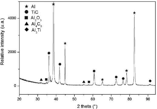
Å). The diffraction patterns were collected over the angular range 20-94 °(2) with a counting time of 200 s.step-1 and a step size of 0.008 °(2). Phase identification in Figure 1 refers to the following ICDD data: Al (00-004-0787), TiC (00-032-1383), Al2O3 (00-046-1212), Al4C3 (00-035-0799), Al3Ti (00-037-1449).
6 observations, scanning electron microscopy was carried out using a SEM FEI Quanta 250 FEG equipped with both a secondary electron detector and a backscattered electron detector (10 keV, 8x10⁻⁶ mbar, working distance 5 mm). For the phase composition, a
working distance of 10 mm, an accelerating voltage of 10 keV and a counting time of 30 s were selected as standard operating parameters to analyze Al, Ti, C and O by EDS. The EDS measurements were subtracted for background and the quantitative analysis was deduced from the electronic standard after PAP corrections.
The foils for TEM were ground on a diamond grinder to a thickness of about 10 m and then thinned by the standard ion beam thinning method. TEM observations were performed using a JEOL 3010 microscope.
Image analysis was carried out using AnalySIS Software (Soft Imaging System Gmbh, www.soft-imaging.net). The particle size distribution is the result of more than 2000 diameter measurements in order to improve the statistic. The size of the particles for the TEM observations was described using Feret’s statistical diameter [36]. The biggest dimension of the particle, associated with Feret’s diameter, was measured as well as the smallest, leading to two particle size distributions for TEM image analysis. The phase proportion and the fraction of TiC particles were determined by threshold analysis of the SEM observations and the results given as a percentage of surface area.
Al-TiC composite density was determined by using an AccuPyc 1330 pycnometer from MicroMeritics (http://www.micromeritics.com). Three sets of 10 measurements each were carried out on the MMC powder. On average, the MMC has a density of 3.178±0.002 g.cm-3. This value has been used in this work to calculate the
volume fraction of reinforcement.
2.3. Mechanical testing
7 from the composite bulk after heat treatment and extrusion (normalized cylindrical shape, 3 mm diameter, length of the reduced section = 19 mm). The crosshead motion was fixed at 2 mm.min-1 and the specimen elongation was measured using an
extensometer (gauge length = 15 mm). The Young’s modulus, proof stress (e0.2%),
ultimate tensile strength (UTS) and maximum elongation were deduced from the mechanical tests.
3. Results and Discussion
3.1. Analytical characterizations of the Al-TiC composite 3.1.1. Phase identification
Figure 1 presents the XRD pattern obtained from the as-formed Al-TiC
composite. Aluminium and titanium carbide are clearly identified as the main phases of the composite. Al3Ti, Al4C3 and Al2O3 are also observed as secondary phases.
Figure 1. XRD pattern of the Al-TiC composite.
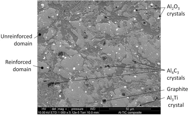
8 As illustrated on a representative view of the Al-TiC composite microstructure (Figure 2), two main domains are identified. First, the darker grey domain in Figure 2 that mainly consists in the Al-rich solid solution with only few TiC particles and that will therefore be referred to as the “unreinforced domain” in the following. Second, some discontinuous lighter grey areas, with a typical size of 35µm, are characterized by a high volume fraction of TiC particles embedded in the Al matrix. These areas will be considered in the following as “reinforced domains”.
Figure 2. Representative view of Al-TiC composite microstructure (x1000). Phase
identification was performed by EDS measurements.
Figures 3.a and b present high magnification SEM observations of the two different domains. Figure 3.a confirms the very low content of TiC particles in the unreinforced domain, estimated at ~ 8% from image analysis. In contrast, in the reinforced domain, the fraction of TiC particles was estimated at ~ 82% from image analysis of Figure 3.b. It is interesting to note that despite the high volume fraction of TiC in this domain, the TiC particles are still individualized and separated by thin veins of Al solid solution, i.e.
9 no clustering was evidenced by SEM observations.
Figure 3. a) High magnification view of the unreinforced domain (x30000). b) High
magnification view of the reinforced domain (x60000).
In addition, the secondary phases Al3Ti, Al4C3, C and Al2O3 detected by XRD
(Figure 1) were also observed in the composite section (Figure 2). Faceted Al2O3
10 section. Al4C3 crystals are well faceted whereas graphite has a jagged appearance. Only
a few crystals of Al3Ti were observed in the composite section.
The proportion of the different domains and secondary phases (percentage of surface covered by the phases) was estimated by threshold image analysis of Figure 2. On average, the Al-TiC composite microstructure consists of 28.2% of unreinforced domain and 68.4% of reinforced domain. Al2O3 and Al4C3-graphite secondary phases
are in minor proportions with 2.3% and 1.1% respectively.
Figure 4 shows the microstructure of the reinforced domains observed by TEM. The particles, of sub-micrometer size, are individualized and surrounded by Al solid solution, i.e. no particle clustering was evidenced by TEM observations. The particles are well faceted, with shapes varying from squares to triangles, pentagons or hexagons. These 2D shape observations are characteristic of a 3D cubic shape, in accordance with the NaCl type crystal structure of TiC. In addition, there is no apparent intermediate phase formed at the interface between the Al matrix and the TiC particles. TiC particles are also localized at the Al solid solution grain boundaries in both the reinforced and unreinforced domains. Due to the high volume fraction of TiC particles in the reinforced domain, a refinement of Al solid solution grain size was observed.
11
Figure 4. TEM image of Al-TiC composite reinforced domain.
Based on these observations, a scenario can be proposed to explain the formation of the composite microstructure. In a first step, the pure Al powder used for dilution melts at about 660°C. Then, liquid Al acts as a getter for oxygen present in the powder compact leading to the formation of the large facetted single crystals of alumina, nucleated from the melt, that are observed as secondary phases in the microstructure. Next, when the temperature exceeds 812°C, Al3Ti and C strongly reacts to form liquid
Al and TiC corresponding to the observed reinforced domains. Considering the high value of the enthalpy of reaction (-101.7 kJ/mol at 1300°C), one can consider a nearly self-heated synthesis reaction and therefore a high reaction rate. The faceted shape of TiC crystals observed on TEM micrograph can be explained by the formation of these particles from a nucleation/growth mechanism in the Al liquid phase produced by the interaction between Al3Ti and graphite. Finally, the presence of Al4C3, graphite and
Al3Ti as secondary phases can be explained by the short heat treatment time that can
12 chemical reaction leading to formation of the Al-TiC composite will be the subject of another publication.
3.2. Analytical characterizations of the TiC particles
In order to characterize the reinforcement in the composite, three specimens were dissolved in hydrochloric acid and the residual material, containing the TiC particles, was collected and analyzed. Table 1 reports the mass of composite dissolved and the mass of residual material recovered for the three specimens.
Table 1. Experimental parameters for the dissolution of the composite.
TiC Al2O3 Carbon Mass of composite (mg) Mass of residual material (mg) %DRX Calculated mass of TiC (mg) a wt.%TiC in the composite b %DRX Calculated mass of Al2O3 (mg) c wt.%Al2O3 in the composite d %DRX Calculated mass of C (mg) e wt.%C in the composite f Sample 1 411.39 151.10 92.9 140.37 34.10 5.3 8.01 1.95 1.8 2.72 0.66 Sample 2 760.08 283.84 92.9 263.69 34.69 5.3 15.04 1.98 1.8 5.11 0.67 Sample 3 270.70 101.88 92.9 94.65 34.96 5.3 5.40 1.99 1.8 1.84 0.68 Average - - - - 34.58 - - 1.97 - - 0.67 a
Mass of TiC =%TiC from XRD * Mass of residual material. b
wt%TiC in the composite= Mass of TiC / Mass of composite. c
Mass of Al2O3 =%Al2O3 from XRD * Mass of residual material. d
wt% Al2O3 in the composite= Mass of Al2O3 / Mass of composite. e
Mass of C =%C from XRD * Mass of residual material. f
wt%C in the composite = Mass of C / Mass of composite.
3.2.1. X-ray diffraction
13 the thermal expansion mismatch effect as the composite cools after heat treatment, improve the signal to noise ratio and reveal secondary phases present in small
quantities. As illustrated in Figure 5, X-ray diffraction reveals the presence of TiC but also Al2O3 and graphite in the residual material. It should be noted that, in comparison
with the Al-TiC composite XRD pattern (see Figure 1), Al, Al3Ti and Al4C3 were not
observed because of their dissolution in hydrochloridric acid during extraction of the TiC particles. The evidence of graphite is correlated with the presence of Al3Ti in the
composite (Figure 2) and seems to indicate that the reaction is not complete. In addition, phase quantification was carried out by Rietveld refinement (Rp = 7.81%, Rwp = 10.4%,
Rexp = 8.54%, 2=1.71). The weight fractions of TiC, Al2O3 and C in the residual
material were 92.9%, 5.3% and 1.8% respectively.
Figure 5. XRD pattern and Rietveld refinement of the residual material.
3.2.2. Volume fraction of TiC in the composite
14 mass of each phase in the residual material after dissolution of samples 1, 2 and 3 was calculated from the weight percentages determined by Rietveld refinement of the pattern presented in Figure 5 (Table 1). Thus, the weight fraction of C in the composite was calculated to be 0.67 wt.% and the average weight fraction of TiC particles in the composite was 34.6 wt.%. Given the density of TiC and the Al-TiC composite, the corresponding volume fraction of TiC was calculated to be 22.3 vol.%. The measured volume fraction of TiC is in very good agreement with the one expected based on the proportion of precursor materials (22 vol.%).
3.2.3. TiC particle size distribution
The particle size distribution (PSD) of the TiC particles was determined by image analysis on SEM and TEM micrographs. SEM observations were carried out on the residual material (solid powder) after dissolution of the Al-TiC composite in HCl, rinsing and drying of the particle suspension. The SEM particle size distribution (SEM-PSD) is shown in Figure 6.a. TEM observations were carried out on Al-TiC composite thin foils using Feret’s statistical diameter [36] and the TEM particle size distributions (TEM-PSD) are illustrated in Figure 6.b.
15
Figure 6. Particle size distributions: a) from SEM observations of the residual material
and, b) from TEM observations of thin Al-TiC composite foil according to Feret’s statistical analysis (black bars = maximum diameter, empty bars = minimum diameter).
Convolution of the particle size distributions obtained by the two different
characterization techniques leads to two main conclusions: i) the average particle size was estimated to be 70 nm, ii) the particles have a narrow size distribution, 88% of them being between 40 and 120 nm in diameter. Again, this narrow distribution with
nanometer-size particles has to be related to the in-situ formation of TiC particles by reactive synthesis. In fact, according to the mechanism of reaction observed by Viala et al. on Al3Ti/C diffusion couples [37], the first step of the chemical interaction between
Al3Ti and C leads to the formation of an Al liquid layer. Next, the reaction proceeds by
diffusion of Ti through this liquid phase from the Al3Ti crystals to the graphite phase.
16 temperature and the heat treatment being sufficiently short to avoid a significant growth, most of the particles have the same size leading to the narrow distribution presented in Figure 6.
3.3. Mechanical properties of the Al-TiC composite
The mechanical properties of the Al-TiC composite, following tensile tests performed on three specimens, are summarized in Table 2 and the values of the maximum elongation is reported in Figure 7 (solid squares).
Table 2. Mechanical properties of the Al-TiC composite
Young’s modulus (GPa) e0.2%a (MPa) UTS b (MPa) Elongation c (%) Failure Energy, K* (J.cm-3) T1 106 442 481 5.8 26.8 T2 106 456 498 5.9 28.1 T3 106 455 493 6.4 30.3 Average 106 451 491 6.0 28.4 Std. Dev.d - 7.8 8.7 0.3 1.8 Error (%) e - 2 2 5 6 a
e0.2% = proof stress
b
UTS=ultimate tensile strength c
Maximum plastic elongation determined with the extensometer d
Std. Dev. = Standard deviation e
17
Figure 7. Maximum elongation as a function of the volume fraction of TiC. The dashed
line illustrates the decrease in maximum elongation as a function of vol.%TiC. The result of the present work (solid square) was not considered in plotting the dashed line.
On average, the new Al-TiC composite presents a Young’s modulus of 106 GPa and a maximum elongation of 6.0%. The influence of the TiC particles is clearly
demonstrated by comparison with the mechanical properties of pure Al (E = 70 GPa, e0.2% = 70 MPa, UTS = 89 MPa, elongation = 33% [8]). In addition, the Young’s
modulus of the present Al-TiC composite is close to the upper limit calculated from the Hashin-Shtrikman model [38,39], respectively 106 and 105 GPa. This might suggest that the in situ reactive synthesis of TiC particles leads to strong interfacial bonding and the attendant load transfer. This is in good accordance with the abrupt interface
observed by TEM (Figure 4.a).
In addition, there is a huge increase in e0.2% and UTS, associated with a decrease in
maximum elongation, in comparison with pure Al. According to Figure 7, extrapolation of data from the literature (dashed line) suggests that a composite with 22 vol.% of reinforcing particles should have a brittle behavior with an elongation nearly equal to 0.
18 Therefore, the experimental elongation of 6% obtained in the present study should be highlighted (Table 2 and solid square on Figure 7).
Regarding the Ultimate Tensile Strength measured on the composite (UTS = 491 MPa, Table 2), a 105% increase is observed compared with the best UTS measured in the literature (239 MPa for 20 vol.%TiC [27]).
In the case of a metal matrix composite, it is quite common to observe that the expected increase in mechanical strength is accompanied by an unwanted decrease in elongation (Figure 7), characterizing a transition toward a brittle behavior. To illustrate the compromise between strength properties and ductility, an Ashby map with failure energy as a function of tensile strength is commonly used. In the present study the failure energy, K*, is calculated using eq. 1.
Eq.1 K*=((e0.2% +UTS)*Max_elong)/2.
Figure 8 presents the literature results in terms of compromise between strength and failure energy. From these, it appears that the failure energy decreases while the volume fraction of TiC reinforcement in the composite (dashed line, Figure 8) increases.
However, in comparison with Satyaprasad’s composite [27], which has the closest TiC volume fraction to the composite of the present study, the failure energy is here
increased by ~100%. In addition, the upper right corner of this Ashby map (hatched area on Figure 8) represents the ideal target for the development of MMCs with optimized properties, i.e. high strength properties without any damage tolerance decrease. As illustrated, the mechanical properties of the Al-TiC composite obtained by the present reactive synthesis process fall into this area, meaning that despite the high volume fraction of TiC reinforcement (22.3 vol.%), the composite offers a good compromise between strength properties and damage tolerance. Thus, to the authors’ knowledge, no other Al-TiC composite described in the literature has such high and interesting
19
Figure 8. Estimated mechanical toughness, identified with the failure energy calculated
as K*=((e0.2%+UTS)*Max_elong)/2, as a function of the ultimate tensile strength. The
volume fractions of TiC reinforcement in the composites are indicated in brackets.
In order to understand the uncommon mechanical behavior of this composite and especially its high elongation and failure energy, fractography was performed on the tensile test specimens (Figure 9). Two main points are highlighted. First, Figure 9.a reveals the presence of dimples containing the TiC particles, which indicates a mainly ductile mode of failure of the Al-TiC composite. It should be noted that the ductile mode of failure has been observed in previous literature studies with lower volume fractions of TiC (5-15 vol.%TiC [39]). Second, no evidence of particle clustering was observed on the fracture surface of the composite.
20
Figure 9. Tensile fracture surface of the Al-TiC composite. a) General view (x400). b)
Details of dimples containing TiC particles (x30000).
Regarding the high volume fraction of TiC in the present composite (22.3 vol.%TiC), the absence of particle clustering and the evidence of a ductile mode of failure must be emphasized and related to the uncommon maximum elongation of 6% observed in the mechanical characterization. This uncommon association of mechanical properties might be explained by the microstructure induced by the reactive synthesis. This microstructure is characterized by the absence of weak points coming either from clustering of theses particles or from defaults (failure initiation) of TiC particles induced by the high energy milling step. As a consequence, the absence of weak area in the microstructure allows the plasticity of the Al-matrix and therefore the high failure energy value that is reported in Figure 8.
21
Conclusion
This paper reports on the microstructure and mechanical properties of an Al-TiC composite obtained by reactive synthesis. Nanosized TiC reinforcements were
synthesized in-situ via the chemical reaction of ball-milled compacted Al3Ti and C
powder mixture during heat treatment of about 1 min at 1000°C. The average weight fraction of TiC reinforcement in the composite is 34.6 wt.% (22.3 vol.%) with an average TiC particle size of 70 nm. The microstructure consists of an intimate mixture of two main domains: an unreinforced percolating matrix, consisting of the Al solid solution with a very low TiC reinforcement content (~8%), and reinforced domains, with a high content of TiC particles (up to 80%) embedded in the Al solid solution. The residual presence of Al3Ti and C is also detected. However, compared to data in the
literature, this composite presents uncommon and promising mechanical properties for a high volume fraction of TiC (22.3 vol.%), with a Young’s modulus of 106 GPa, e0.2%
of 450 MPa, UTS of 490 MPa and maximum elongation of 6%. This compromise between strength and ductility, despite the high particle volume fraction, is associated with the absence of particle clustering, even in the reinforced domains. The remarkable properties of the present Al-TiC composite and particularly the homogeneous size and dispersion of the reinforcing particles are attributed to the original reactive synthesis route that is characterized by a high nucleation rate of the TiC particles in liquid aluminium.
Acknowledgements
The work was funded by the French National Research Agency’s “NanoTiCAl” program, no. ANR-2011-RMNP-011. The authors wish to thank the “Centre
22 the its help and advice during the SEM observations.
References
[1] Miserez AGT. Fracture and toughening of high volume fraction ceramic particle reinforced metals [dissertation]. Lausanne: EPFL; 2003.
[2] Tjong SC, Ma ZY. Microstructural and mechanical characteristics of in situ metal matrix composites. Mater Sci Eng 2000;R29:49-113.
[3] Frage N, Froumin N, Dariel MP. Wetting of TiC by non-reactive liquid metals. Acta Mater 2002;50(2):237-245.
[4] Dezellus O, Eustathopoulos N. Fundamental issues of reactive wetting by liquid metals. J Mater Sci 2010;45(16):4256-4264.
[5] Schwarz K. Band structure and chemical bonding in transition metal carbides and nitrides. Crit Rev Solid State 1987;13:211-257.
[6] Contreras A, Angeles-Chavez C, Flores O, Perez R. Structural, morphological and interfacial characterization of Al–Mg/TiC composites. Mater Character 2007;58:685-693.
[7] Albiter A, Leon CA, Drew RAL, Bedolla E. Microstructure and heat-treatment response of Al-2024/TiC composites. Mater Sci Eng 2000;A289:109-115.
[8] Karantzalis AE, Wyatt S, Kennedy AR. The mechanical properties of Al-TiC metal matrix composites fabricated by a flux-casting technique. Mater Sci Eng
1997;A237:200-206.
[9] Clyne TW. Metallic composite materials. In: Cahn RW, Haasen YP, editors. Physical metallurgy. Amsterdam: Elsevier, 1996. p. 2568-2625.
[10] Humphreys FJ, Basu A, Djazeb MR. The microstructure and strength of particulate metal-matrix composites. In: Proceedings of 12th Riso international symposium on materials science. Roskilde, September, 1991. p. 51-66.
23 [11] McKimpson MG, Scott TE. Processing and properties of metal matrix composites containing discontinuous reinforcement. Mater Sci Eng 1989;A107:93-106.
[12] Lloyd DJ. Aspects of fracture in particulate reinforced metal matrix composites. Acta Metall Mater 1991;39(1):59-71.
[13] Jiang WH, Song GH, Han XL, He CL, Ru HC. Synthesis of TiC/Al composites in liquid aluminium. Mater Lett 1997;32:63-65.
[14] Harata M, Choh T, Kobashi K. Effect of alloying elements on TiC particulate dispersion in aluminium matrix composites. J Japan Inst Metals 1990;54:1382-1391. [15] Stefanescu DM, Dhindaw BK. Principles of solidification – Behavior of insoluble particles at the solid/liquid interface. In: Thompson M, editor. Metals Handbook. Metals park: ASM Int, 1988. p.142-147.
[16] Jin I, Lloyd DJ. Solidification of SiC particulate reinforced Al-Si alloy composites. In: Masounave J, Hamel FG, editors. Fabrication of particulates reinforced metal matrix composites. Materials Park: ASM Int, 1990. p.47-52.
[17] Lloyd DJ, Lagace H, McLeod A, Morris PL. Microstructural aspects of aluminium-silicon carbide particulate composites produced by a casting method. Mater Sci Eng 1989;A107:73-80.
[18] Mortensen A. Interfacial phenomena in the solidification processing of metal matrix composites. Mater Sci Eng 1991;A135:1-11.
[19] Selcuk C, Kennedy AR. Al–TiC composite made by the addition of master alloys pellets synthesized from reacted elemental powders. Mater Lett 2006;60:3364-3366. [20] Kennedy AR, Wyatt SM. The effect of processing on the mechanical properties and interfacial strength of aluminium/TiC MMCs. Compos Sci Technol 2000;60:307-314.
[21] Nukami T, Flemings MC. In-situ synthesis of TiC particulate-reinforced aluminum matrix composites. Metall Mater Trans 1995;A26(7):1877-1884.
24 TiC:Al composites. Mater Sci Eng 1999;A265:71-76.
[23] Shyu RF, Ho CT. In situ reacted titanium carbide-reinforced aluminium alloys composite. J Mater Process Technol 2006;171:411-416.
[24] Premkumar MK, Chu MG. Al-TiC Particulate composite produced by a liquid state in situ process. Mater Sci Eng 1995;A202:172-178.
[25] Sahoo P, Koczak M. Analysis of in situ formation of titanium carbide in aluminium alloys. Mater Sci Eng 1991;A144:37-44.
[26] Kennedy AR, Weston DP, Jones MI, Enel C. Reaction in Al-Ti-C powders and its relation to the formation and stability of TiC in Al at high temperatures. Scripta Mater 2000;42:1187-1192.
[27] Satyaprasad K, Hehajan YR, Bhanuprasad VU. Strengthening of Al/20v/o TiC composites by isothermal heat treatment. Scripta Metall Mater 1992;26:711-716.
[28] Kennedy AR, Weston DP, Jones MI. Reaction in Al–TiC metal matrix composites. Mater Sci Eng 2001;A316:32-38.
[29] Mitra R, Fine ME, Weertman JR. Chemical reaction strengthening of Al/TiC metal matrix composites by isothermal heat treatment at 913 K. J Mater Res 1993;8(9):2370-2379.
[30] Pandey AB, Mishra RS, Mahajan YR. Effect of isothermal heat treatment on the creep behaviour of an A1-TiCp composite. Mater Sci Eng 1996;A206:270-278.
[31] Murphy AM, Clyne TW. The effect of initial porosity and particle clustering on the tensile failure of cast particulate MMCs. In: Proceedings of ICCM-10 Conference. Whistler, August, 1995. p.35-42.
[32] Rohatgi PK. Interfacial phenomena in metal matrix composites. In: Dhingra AK, Fishman S, editors. Interfaces in MMCs. New Orleans: AIME, 1986. p.185-202. [33] Lagace H, Lloyd DJ. Microstructural analysis of Al-SiC composites. Canadian Metall Q 1989;28(2):145-152.
25 [34] Scientific Group Thermodata Europe (SGTE), Thermodynamic properties of
inorganic materials, Springer, Verlag Berlin Heidelberg (1999).
[35] Chaffron L, Nunes D, Patent FR1350249, Procédé d'élaboration d'un matériau nanocomposite Al/TiC.
[36] Walton WH. Feret’s statistical diameter as a measure of particle size. Nature 1948;162:329-330.
[37] Viala JC, Peillon N, Clochefert L, Bouix J. Diffusion paths and reaction
mechanisms in the high-temperature chemical interaction between carbon and titanium aluminides. Mater Sci Eng 1995;A203:222-237.
[38] Hashin Z, Shtrikman S. A variational approach to the elastic behavior of multiphase minerals. J Mech Phys Solids 1963;11:127-140.
[39] Tong XC, Fang HS. Al-TiC composites in situ–processed by ingot metallurgy and rapid solidification technology: Part II. mechanical behavior, Metall Mater Trans 1998;29A:893-902.
[40] Mazaheri Y, Meratian M, Emadi R, Najarian AR. Comparison of microstructural and mechanical properties of Al-TiC, Al-B4C and Al-TiC-B4C composites prepared by