an author's https://oatao.univ-toulouse.fr/25491
http://doi.org/10.1109/WFCS.2019.8758022
Amari, Ahmed and Mifdaoui, Ahlem QoS-Aware Ring Redundancy Protocol (QoS-ARRP) for High-Availability Ethernet Networks. (2019) In: 15th IEEE International Workshop on Factory Communication Systems (WFCS'19), 27 May 2019 - 29 May 2019 (Sundsvall, Sweden).
QoS-Aware Ring Redundancy Protocol
(QoS-ARRP) for High-Availability Ethernet
Networks
Ahmed AMARI and Ahlem MIFDAOUI
ISAE-SUPAERO, Universit´e de Toulouse, France
(email: [email protected])
Abstract—During the last decade, Ethernet’s significance has increased in many embedded systems application areas, such as automotive, avionics and automation. However, guaranteeing the required availability level for such applications on Ethernet is still a hot research topic. In this specific area, we propose in this paper a new redundancy protocol for high availability Ethernet networks, called QoS-Aware Ring Redundancy Protocol (QoS-ARRP). First, the specifications of such a protocol are detailed, including the frame redundancy and filtering management, the auto-configuration mechanisms, as well as the maximum recovery time analysis. Second, the numerical results of the recovery time have shown the impact of the protocol parameters to tune and the trade-off between availability and scalability of the network. Moreover, we have benchmarked the state-of-the-art results on the recovery time against ours. A noticeable enhancement of the maximum recovery time with our proposal, thus of the availability level, has been highlighted.
Index Terms—Real-Time Ethernet, Availability, Redundancy, QoS, IEC62439, IEEE 802.1CB.
I. INTRODUCTION
During the last decade, Ethernet’s significance has increased in many embedded systems application areas, such as auto-motive, avionics and automation. Due to its high bandwidth, scalability and low operating costs, Ethernet becomes very appealing to succeed legacy networks, such as CAN [1]. Nev-ertheless, guaranteeing stringent predictability and availability requirements of safety-critical embedded systems with such a technology is still a hot research topic. This fact is due to its native non-deterministic behavior and the long switchover time of its common redundancy protocols, e.g., few seconds with the Spanning Tree Protocol (STP) [2] and hundreds of milliseconds with the Rapid STP (RSTP) [2].
Various approaches improving Ethernet predictability have been standardized by the International Electrotechnical Com-mission (IEC) and published in IEC 61784-2 [3], such as EtherCAT [4], Profinet/ IRT [5] and PowerLink [6].
However, these solutions have been developed for specific domains, which limits their interoperability with standard (classic) Ethernet technology. To cope with this issue, the IEEE 802.1 TSN (Time Sensitive Networking) [7] task group is currently working on the standardization of the main fea-tures to enable real-time communication on Switched Ethernet systems, such as scheduling [8] and redundancy [9].
In this paper, our main concern is guaranteeing the high availability requirement in Ethernet networks with mixed-criticality traffic pattern, e.g., hard real-time, soft real-time and best-effort, through using redundancy protocols. As we detail in Section II, most common redundancy protocols can be cate-gorized into two main classes, static and dynamic. The former, e.g., [10][9], is generally based on fully duplicated networks, where both networks are used in parallel to increase the fault
detection coverage. This class offers a zero recovery time1, but
also has high deployment costs and limited resource efficiency. On the other hand, the dynamic redundancy solutions [11] [12] [13] have been introduced to decrease the installation costs and improve resource efficiency through using a backup path in case of failures, but they are more suitable for soft real-time or best-effort traffic tolerating a bounded recovery time. Hence, each existing redundancy protocol class has been optimized for a specific use case with limited support of mixed-criticality traffic pattern.
To remedy the above problems, we have specified a new
redundancy protocol, called QoS2-Aware Ring Redundancy
Protocol (QoS-ARRP), with the following key advantages: (a) support of mixed-criticality traffic pattern, (b) low configu-ration effort and (c) low deployment costs. This redundancy protocol has been incorporated in AeroRing network [14], a multiple-ring Ethernet network for avionics.
Contributions: we conduct in this paper the analysis of the recovery time of QoS-ARRP. The numerical results show a zero recovery time for hard real-time traffic and bounded for soft real-time and best-effort traffic, e.g., less than 4.5ms for a large-scale network of 200 nodes. Moreover, we benchmark the state-of-the-art results on the recovery time against ours. A noticeable enhancement of the maximum recovery time with our proposal, thus of the availability level, has been highlighted.
The rest of the paper is organized as follows. We report the main related work in Section II. The specifications of QoS-ARRP and the analysis of the recovery time are detailed in Section III. Numerical results to validate our proposal when varying the protocol parameters and in reference with existing protocols are illustrated in Section IV. Finally, we draw the main conclusions and future work in Section V.
1”the maximum time from failure to become fully operational again in case of a single permanent failure”
II. RELATEDWORK
To improve the availability level in Ethernet, many redun-dancy protocols based on ring topologies have been standard-ized in IEC 62439 series [12] [10] [11] [13] and more recently in TSN [9]. Such topologies enable high availability level, while limiting cabling costs. They actually provide an implicit redundant path through introducing only one additional con-nection between the two end nodes, compared to line or star topologies [15]. These solutions can be categorized into two main classes, static and dynamic. The main features of these protocols are summarized in Table I.
The most relevant static protocols are the Parallel Redun-dancy Protocol (PRP) [10] and High-availability Seamless Redundancy protocol (HSR) [10]; whereas, the main dynamic protocols are Distributed Redundancy Protocol (DRP) [11], Media Redundancy Protocol (MRP) [12] and Ring-based Redundancy Protocol (RRP) [13].
Both PRP and HSR offer a zero recovery time when a failure occurs, through guaranteeing two redundant paths for each transmitted data. The PRP handles this feature due to a fully redundant network, i.e., two parallel networks, where most of the devices are attached to both parallel networks, and each data is duplicated at the transmission and filtered at the reception using a specific device, called Dual Attached Node (DAN). The HSR protocol achieves the same purpose through a daisy-chain ring topology, where each device has both ports operating in parallel and called Doubly Attached Node with HSR protocol (DANH). A source node duplicates the data message on both directions, then the destination node consumes only the first valid one. The unicast messages are filtered by the destination and the broadcast messages by the source using the MAC addresses to avoid infinite message looping.
The MRP is based on a manager, called Media Redundancy Manager (MRM), that monitors the status of the network and the other nodes, called Media Redundancy Clients (MRCs). Each equipment integrates an internal switch with two ports, and supports three status: disabled, when the port is down; blocked, the forwarding function is disabled; forwarding, the port can receive and forward messages. In the nominal case, the ring is closed and all MRCs are forwarding the data, except the MRM which blocks one of its ports to create a logical line topology and to avoid the infinite message looping. Furthermore, the MRM monitors the status of the network by sending periodically Test frames on both ports, and if the frames are received on the opposite ports, then the ring is closed. However, if the frames are lost, then the MRM concludes that the network is faulty. In addition to that, each MRC monitors the local connection with its neighbors, if it detects a failure or a recovery, then it announces it to the MRM by a LinkChange frame. In both scenarios, the MRM activates both ports to transmit data and informs the MRCs about the topology change by sending TopoChange frames.
The DRP implements a local failure detection mechanisms, where each equipment can check the status of its neighbors by sending a link test frame ”LinkCheck” to detect failures. It transforms the ring topology into a line topology by disabling
a port of an elected device (the device with the highest ID is elected) to avoid infinite packet looping. In addition to the local failure detection, DRP implements a centralized failure detection mechanism to check the ring status in a cyclic manner, i.e., during each cycle, only one equipment can check the ring status via a ring test frame ”RingCheck”, gather and broadcast the information to the rest of equipment in case of a change. When a failure occurs, the device with the blocking port activates its port to allow packets transmission. It is worth noting that an accurate synchronisation protocol is required to manage such a cyclic process.
The RRP manages the failure detection and network config-uration dynamically. Based on the physical layer mechanisms as specified in ISO/IEC 8802-3:20000 Clause 24, the devices can detect their neighbors and also occurred failures, then they share these information through the network. Based on these information, all network devices will build their routing tables in a distributed way. However, RRP transforms the ring topology into a line topology to avoid infinite packet looping, through the selection of two adjacent devices, called Ring Network Managers (RNMs), and disabling one of their ports. The benchmarking of these existing protocols vs the main identified requirements is illustrated in Table II. We particu-larly consider the following requirements:
• Deployment costs: this metric is evaluated according
to the required redundancy level of the network: fully redundant or not;
• Fexibility: this metric is evaluated according to the
(re)configuration effort needed to enable the failure de-tection and recovery mechanisms;
• Resource efficiency: this metric is evaluated according
to the maximum available bandwidth accounting for the protocol overhead;
• Availability: this metric is evaluated according to the
recovery time.
Both static protocols, PRP and HSR offer a high flexi-bility and availaflexi-bility levels, since they do not require any (re)configuration mechanism and offer a zero recovery time when a failure occurs. However, both protocols limit the resource efficiency, since the available bandwidth is only of 50% due to the duplication of all packets on both networks (resp. ring directions) for PRP (resp. HSR). However, HSR was designed to reach the same availability level as PRP using redundancy within the same network, instead of using fully redundant one, which allows reducing the deployment costs.
On the other hand, the dynamic protocols allow reducing the deployment costs through enabling redundancy within the same network. However, they degrade the availability level by transforming the ring into a line topology to avoid infinite message looping. Moreover, RRP offers the best flexibility level due to its dynamic mechanisms to detect failures and configure the network, in comparison with DRP and MRP. Finally, the MRP guarantees the lowest resource efficiency level, in comparison with DRP and RRP, due to its high overhead to detect failures, i.e., local and global mechanisms. We can notice that each existing protocol satisfies some requirements better than others, but there is no best protocol in terms of all the requirements.
TABLE I
MAIN CHARACTERISTICS OF RING-BASED REDUNDANCY PROTOCOLS
Characteristic PRP HSR MRP DRP RRP
Topology Redundant Network Ring Line Line Line
Frame Redundancy Yes Yes None None None
Failure detection N.A. N.A. Local + Global Local + Global Local
Reconfiguration N.A. N.A. Centralized Centralized Distributed
Frame Filtering Using a specific Within the nodes Manager Elected node 2 ring network
device based on MAC @ managers
TABLE II
BENCHMARKING OF REDUNDANCY PROTOCOLS SUPPORTING RING
TOPOLOGY
Protocol Costs Flexibility Resource Efficiency Availability
HSR Low High Low High
PRP High High Low High
MRP Low Low Low Medium
DRP Low Low Medium Medium
RRP Low High Medium Medium
Hence, to overcome these limitations, our introduced redun-dancy protocol QoS-ARRP has the main following features:
• Using ring topology to decrease the deployment
costs-unlike the existing dynamic protocols which transform the ring into line, the QoS-ARRP takes the full advantage of the multi-path feature of ring topologies due to the frame filtering functions, implemented within each device to avoid infinite packet looping and detailed in Section III-A;
• QoS-aware redundancy management to improve
re-source efficiency and availability level- the hard real-time traffic is sent on both redundant paths to guarantee a zero recovery time; and the soft real-time and best-effort traffic is sent only on the shortest path with a short recovery time, e.g., less than 4.5ms for a large-scale network of 200 nodes. This feature leads to better availability level than classic dynamic protocols, while improving the resource efficiency in comparison to the static protocols;
• Plug and play devices to increase the flexibility- the
devices are incorporating an auto-configuration mecha-nism, described in Section III-C, to build dynamically the routing tables during the different phases of network oper-ations, i.e., start-up, nominal and non-nominal operoper-ations, to offer a high flexibility level and limited configuration effort as static redundancy protocols.
III. QOS-AWARERINGREDUNDANCYPROTOCOL
(QOS-ARRP)
The QoS-ARRP operates within the end nodes at layer 2 (in the ISO OSI network model) and its use is completely transparent to high layer protocols, e.g., UDP and TCP. The QoS-ARRP is implemented at the software level and is effec-tive for any Ethernet speed, e.g., 100Mbps, 1Gbps or faster interfaces. At the hardware level, it supports a ring topology, where each ring device incorporates a 3 port Ethernet switch, as illustrated in Fig. 1, and has the following requirements:
• Cut-Through forwarding technique: the packet is
for-warded just after its identification, i.e., only the header of each packet is decoded to determine its destination;
• Disabling the Spanning Tree protocol and enabling the
specific QoS-aware routing algorithm (described in Sec-tion III-A);
• Strict priority scheduling with at least 3 queues: the
highest priority queue is reserved to QoS-ARRP control messages; whereas the medium and low priority queues are for hard real-time messages and soft real-time or best-effort messages, respectively. Moreover, the prioritization is compliant with IEEE 802.1Q specifications [16].
Fig. 1. The QoS-ARRP switch ports
A. Frame Redundancy and Filtering Management
The main idea of the QoS-ARRP is to enable a frame redun-dancy management through a QoS-aware routing algorithm. The latter allows the message (re)transmission within each ring device according to the priority level, and the main rules of such an algorithm are described herein.
First, the QoS-ARRP control messages are used for network management issues, such as: (i) building/updating the routing tables of the ring devices; (ii) the failure detection man-agement; (iii) neighbor status checking. For the two former, the control messages are sent on both ring ports to ensure a high availability level; whereas for the latter, the control messages are only sent to the neighbors to check their status and guarantee a fast failure detection. The failure detection mechanism is detailed in Section III-B.
Afterwards, the messages received from port 3, i.e., from the connected equipment in Fig. 1, are transmitted to port 1 or/and 2 according to their priority level as follows:
• Unicast and broadcast messages with the medium priority,
i.e., hard real-time messages, are sent through both ports to guarantee messages redundancy;
• Unicast messages with low priority, i.e., soft real-time
and best-effort messages, are sent through the port cor-responding to the shortest path to offer short delays;
• Broadcast messages with low priority are transmitted through a predefined or a random port;
• Non 802.1Q tagged messages are treated as messages of
low priority.
Messages received from port 1 or 2 are treated according to their priority level and destination address. If the destination address corresponds to the connected equipment, then the message is sent to port 3; else, the messages are forwarded to the opposite port. It is worth noting that each message with the medium priority is sent to port 3 only if its replica has not been received yet. This last point is related to the filtering rules, implemented within the ring devices.
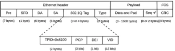
Fig. 2. QoS-ARRP frame structure
Indeed, to take the full advantage of redundant paths on ring topologies while avoiding infinite message looping, the QoS-ARRP specifies the following filtering rules within the ring devices:
• for transmission where both the message and its FCS field
are correct:
– Unicast messages, independently from their priority level, are filtered from the ring within the destination device. In addition, in the specific case of hard real-time messages, the destination node delivers only the first valid received replica. This fact is enabled due to the added sequence number of 2 bytes within the payload field, as illustrated in Fig. 2, which allows identifying and discarding the replicas. When the destination receives a correct hard real-time message, it stores the couple (src MAC, sequence number); and once the replica is received, or after a timeout, the stored couple (src MAC, sequence number) is removed from the memory. It is worth noting that the timeout is a parameter fixed by the network designer, which must be greater than the maximum end-to-end delay;
– Broadcast messages, independently from their
priority level, are filtered within the source node;
• for transmission where the FCS field is not correct,
i.e., detected error, the filtering rules are similar to the previous case;
• for transmission where the message is not correct and its
FCS field is correct, i.e., non detected error: if the error occurs on the header, then the frame can be eliminated from the network by any ring device based on its routing table, i.e., the source or the destination MAC address is not within the routing table.
B. Failure Detection and Recovery
To reduce the failure detection time, the QoS-ARRP uses a local failure detection mechanism. In practice, any QoS-ARRP
device has to consider a connection as down with a neighbor, if it does not receive any message from its neighbor during a certain period called ”detection period”. This detection period can be easily tuned by the network designer. Furthermore, the QoS-ARRP uses the link status information provided by the physical layer mechanisms of Ethernet, as specified in ISO/IEC 8802-3:20000 Clause 24 [17].
Fig. 3. Sub-structure of a control message
Therefore, the QoS-ARRP failure detection mechanism is based on three main steps:
(i) First, if a ring device has no data to transmit to its neighbor(s), then it announces periodically each announcing
period its status to the neighbor(s) through sending control
messages. These messages have the minimum Ethernet frame length of 64 bytes, and are identified with a CTL field set to ”0000” and a type value ”0x9000”, as illustrated in Fig. 3;
(ii) Second, any ring device, which did not receive any data or control message from a ring port for a duration equal to the
detection period3, will detect a failure. Afterwards, this ring
device informs the other ring devices about the failure through a control message, which has the same structure illustrated in Fig. 3 and a CTL field set to ”0010”;
(iii) Finally, any ring device receiving the control message with a CTL code ”0010” from the device detecting the failure will update its routing table to bypass the failure during the data transmission. This step is based on the auto-configuration mechanism of the QoS-ARRP (described in Section III-C).
It is worth noting that such a failure detection mecha-nism is a distributed mechamecha-nism and it has no restrictions on the number of failures. Concerning the failure recovery process, when the ring device that has detected the failure starts receiving messages (data or control) from its neighbor again, then it deduces that the connection is operational again. Consequently, it sends a control message with a CTL code ”0010” to enable the routing tables update of the other ring devices; thus to take into account the failure recovery, based on the auto-configuration mechanism of the QoS-ARRP.
C. Auto-Configuration Mechanism
To reduce the configuration effort, the QoS- ARRP provides an auto-configuration mechanism to build and update the rout-ing tables within all the rrout-ing devices. This auto-configuration mechanism enables the QoS-aware routing algorithm to trans-mit the low priority level messages, i.e., soft real-time and best-effort, on the shortest path (ports 1 or 2 in Fig. 1).
The QoS-ARRP auto-configuration mechanism is enabled through the exchanged control messages between the ring devices. The structure of such control messages is illustrated in Fig. 4 and consists of: (i) a CTL field set to ”0001”; (ii) a NBAD field to encode the number of MAC addresses inserted 3This period is higher than the announcing period and covers in general the reception of more than one control message.
in ADDx fields; (iii) ADDx fields to insert the MAC addresses of the different ring devices. This kind of control message can contain up to 249 MAC addresses if we respect the maximum Ethernet size of 1500 bytes, and up to 1499 MAC addresses if the use of jumbo frames, i.e., up to 9000 bytes, is enabled.
Fig. 4. Sub-structure of a control message to build/update the routing tables The QoS-ARRP auto-configuration mechanism is based on the main following steps:
• First, any ring device detecting a topology change
event, i.e., equipment connection, device/link failure or
recovery, sends periodically4on both ring ports a control
message with a NBAD field set to zero and empty ADDx fields, to update the routing tables of the other ring devices;
• Second, any ring device receiving such a control message
will contribute in building/updating the routing tables through:
1) updating the control message by incrementing the NBAD counter, inserting its MAC address at the end of the ADDx list to respect the physical order of the ring and computing the new FCS field; 2) forwarding the updated control message to the next
device;
3) updating its routing table through inserting the MAC addresses of new devices and deleting the ones that no longer exist;
• Third, when receiving such a control message on one
of the ring ports of the device that has detected the topology change event, then that device deduces that it has a neighbor on that port and it is no longer the last device of the segment. Consequently, it stops the periodic transmission of the control messages with a CTL ”0001” on the corresponding ring port; and it stops completely transmitting control messages on both ring ports when detecting both neighbors;
• Finally, the transmission of such control messages stops
completely when the ring is closed; thus all the routing tables are up to date.
Figures 5 and 6 illustrate the different steps of the QoS-ARRP auto-configuration mechanism for a failure detection event and a failure recovery event, respectively. As we can notice in Fig. 5, after the failure detection of the ring device 5 by the ring devices 4 and 6, the latter send control messages on both opposite ring ports, to inform the rest of the ring devices about the failure and to enable their routing tables update. Afterwards, at the reception of the control message on a ring port, each ring device updates its routing table by erasing the MAC addresses located after the device detecting the failure, 4The period can be tuned according to the application requirements by the network designer
Fig. 5. The QoS-ARRP Auto-configuration Mechanism after a failure
detection
e.g., the device 3 erases all MAC addresses in its routing table located after the device 4 (5,6,1,2), when receiving the control message on the corresponding ring port.
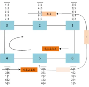
Fig. 6. The QoS-ARRP Auto-configuration Mechanism after a failure
recovery
In Fig. 6, after the failure recovery of the ring device 5, the latter sends control messages on both ring ports to enable the routing tables update of the other ring devices. Therefore, each ring device receiving the control message inserts its own MAC address, increments the NBAD and updates the FCS. At the end, the device 5 receives the control messages on its both ring ports containing the list of MAC addresses respecting the physical order to build its routing table, e.g., the list (4, 3, 2, 1, 6) on the left port.
D. Maximum Recovery Time Analysis
According to the IEC 61784-2 [3] and IEC 62439-1 [18], one of the most relevant Performance Indicators (PIs) of Ring Redundancy Protocols is the Maximum Recovery Time. This indicator is essential to evaluate the network availability, a key requirement for safety-critical embedded systems. Moreover, this recovery time has not to exceed the grace time [18], i.e., time during which we tolerate a system degradation, which is typically less than 20ms for safety-critical systems. In this section, we express the maximum recovery time induced by our proposed protocol QoS-ARRP.
According to the QoS-ARRP, since the hard real-time traffic is sent on both paths, then in case of a failure occurrence the guaranteed recovery time for this kind of traffic is zero. Hence, we will express herein the maximum recovery time guaranteed for the soft real-time or best-effort traffic sent only on the shortest path; thus can be submitted to an additional delivery delay in case of a failure occurrence.
The maximum recovery time of QoS-ARRP, Trecovery,
covers the duration of the different steps, which need to be handled since the failure occurrence until the ring reconfiguration to bypass this failure. Therefore, to compute such a maximum recovery time, we need to consider the main following steps of QoS-ARRP, depicted in Fig. 7.
Failure Detection
First, when a failure occurs, the QoS-ARRP needs a detection time, Tdetection, to be aware of the failure, e.g., faulty device or
link. In absence of received traffic on one of the ring ports of a given device, the latter sends a control message to its neighbor on that port. After a maximum number of control messages, Ndetect, sent periodically each Plocal detectwithout receiving
a feedback from the corresponding neighbor, the QoS-ARRP device detects a failure. Furthermore, the ring device is able to detect a failure based on the link status information provided by the physical layer of the IEEE 802.3 [17], which detects the
failure after a network fault sense time, Tf ault sense. Hence,
the detection time is as follows:
Tdetection= min(Tf ault sense, Ndetect× Plocal detect) (1)
For instance, Tf ault sense = 2ms for the Gigabit Ethernet
[17].
Failure Declaration
After the failure detection, the ring devices, neighbors of the failure, need to declare the failure to all the other devices; thus to enable the ring reconfiguration and bypass the failure. This declaration corresponds to the transmission time of one control message with a CTL code ”0010” and of minimum
size Lctl, i.e., Lctl/C, where C is the transmission capacity
of the network.
In addition, due to the QoS-aware redundancy management, the control message with the highest priority 0 can be at the worst-case delayed by at most one maximum length packet
of low priority pp at each crossed device, Lpp. This blocking
delay, TBlocDelay, is as follows:
TBlocDelay= (M − 3) × (
maxpp>0Lpp
C + τ ) (2)
, where τ is the technological latency of each crossed device, and (M − 3) is the number of crossed devices apart the both detecting the failure and the faulty one.
Hence, using Eq. (2), the declaration time is as follows: Tdeclaration= Lctl/C + TBlocDelay (3)
Ring Reconfiguration
Now that all the ring devices are aware of the occurred failure, they need to update their routing tables to bypass the failure when transmitting data. This duration corresponds
to the routing table update, Ttab−up, which is equivalent to
the transmission time of the control message containing the
list of the MAC addresses, Ladd−list, exchanged between
the ring devices to update their routing table. As detailed in Section III-C, QoS-ARRP needs only one control message to update the routing table, which inherently reduces the control overhead. Moreover, as illustrated in Fig. 5, since the control message for ring reconfiguration (with a CTL code ”0001”) is sent right after the control message for failure declaration (with a CTL code ”0010”), the blocking delay of the reconfiguration message due to low priorities has been already integrated in the declaration time in Eq. (3).
Hence, the ring reconfiguration time corresponds to the time needed for routing table update, which is as follows:
Ttab−up=
Ladr−list
C (4)
, where Ladd−list is equal in bytes to 42 + max(42, 2 + 6 ×
(M − 2)) with: 42 bytes for the overhead of the Ethernet header (with the 802.1q tag), 12 bytes for the IFG, 2 bytes to identify the message type, and (M − 2) × 6 bytes due to the size of an Ethernet MAC address multiplied by the maximum number of crossed devices (M − 2), i.e., all the devices apart the both detecting the failure.
Therefore, based on Eqs. (1), (3) and (4), the maximum recovery time is as follows:
Trecovery= Tdetection+ Tdeclaration+ Ttab−up (5)
It is worth noting that the propagation delay is neglected herein, since it is typically less than 50 ns per 10m for a cable of category 5.
IV. NUMERICALRESULTS
In this section, we report the numerical results of the maximum recovery time of the QoS-ARRP protocol. First, we present the considered case study and the considered network configurations. Afterwards, we discuss the impact of varying the protocol parameters that need to be tuned by the designer on the maximum recovery time. Finally, we compare the QoS-ARRP with existing protocols to evaluate its efficiency. A. Case Study
We consider the case study with the following assumptions:
• The network is a ring connecting M devices;
• The transmission capacity is C = 1Gbps;
• Each device has a technological latency τ = 600ns;
• Each device generates a periodic data flow with a period
of 2ms and a maximum packet length of 1500bytes. The
latter is used to compute the TBlocDelay in Eq. (2).
We experiment various network configurations, as illustrated in Table III, through varying the network size M and the proto-col parameters to tune, i.e., (Tdetection, Ndetect, Plocal detect),
to assess their impact on the recovery time.
It is worth noting that the lowest value of Plocal detect
is higher than the transmission time of one control message with a minimum length (64 bytes). Moreover, the highest value of the same parameter multiplied by the maximum
number of Ndetect = 3 allows a Tdetection smaller than the
Tf ault sense= 2ms of the Gigabit Ethernet.
The results are illustrated in Figures 8, 9, 10 and 11. TABLE III NETWORKCONFIGURATIONS Parameter Range M [10 : 10 : 200] Tdetection [0.1 : 0.2 : 3]ms Ndetect [1 : 1 : 3]
Plocal detect (low(10us), medium(100us), high(600us))
B. Impact of Protocol Parameters on Recovery Time
Tdetection (s) ×10-3 0 0.5 1 1.5 2 2.5 3 Recovery time (s) ×10-3 0.5 1 1.5 2 2.5
Fig. 8. The impact of Tdetectionon the Maximum Recovery Time for (M =
40, Tdetection∈ [0.1 : 0.2 : 3]ms) Network size 0 20 40 60 80 100 120 140 160 180 200 Recovery time (s) ×10-3 0.5 1 1.5 2 2.5 3 3.5 4 4.5 5 Tdetection=0.5ms T detection=1ms T detection=2ms
Fig. 9. The impact of Tdetection on the Maximum Recovery Time vs the
Network Size for (M ∈ [10 : 10 : 200], Tdetection∈ {0.5, 1, 2}ms)
As shown in Fig. 8, when increasing the Tdetection from
0.1ms until 2ms, the maximum recovery time increases lin-early from 0.6ms until 2.5ms and then becomes constant.
This is due to the fact that Tdetection is at most equal
to the Tf ault sense of the Gigabit Ethernet, i.e., 2ms, and
Tdeclaration and Ttab−up (Eqs. (3) and (4) respectively) are
also constant for a fixed network size, i.e., M = 40. Con-sequently, for a medium-scale network, the failure detection phase has the most noticeable impact on the recovery time, in comparison to the failure declaration and the ring configuration phases.
However, when increasing the network size, as illustrated in Fig. 9, we actually observe the inverse for a large-scale network. For instance, for M = 200, the recovery time is
about 3ms for Tdetection = 0.5ms; thus, less than 17% of the
recovery time is due to the failure detection phase.
Hence, to better understand the impact of the detection time parameter on the recovery time, we have varied the parameters Ndetect and Plocal detect, as depicted in Figures 10 and 11.
There are actually two main observations to note:
(i) for a fixed network size, the maximum recovery time grows
logarithmically with the Ndetect, e.g., for M = 200, when the
Ndetectincreases from 1 to 3, i.e., ×3, the recovery time grows
only from 3.1ms to 4.4ms, i.e., ×0.42;
(ii) the maximum recovery time for a fixed network size
increases in a less noticeable way with the Plocal detect but
still grows logarithmically, e.g., for M = 200, the recovery
time goes from 2.6ms to 4.4ms, i.e., ×0.69, when Plocal detect
increases from 10us to 600us, i.e., ×60.
These results infer that the protocol parameter Ndetect has
higher impact on the recovery time than Plocal detect.
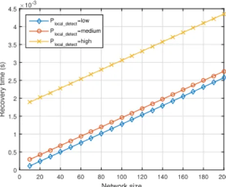
As shown in Figures 9, 10 and 11, the recovery time grows linearly in terms of the network size for a fixed protocol parameter, i.e., Tdetection, Ndetectand Plocal detect. This fact
is consistent with the recovery time expression in Eq. (5),
where Tdeclarationand Ttab−upgrow linearly with the network
size M while Tdetection stays constant. In addition, to avoid
losing more than one data packet sent by each device because of a failure occurrence, we need to guarantee a maximum recovery time at most equal to 2ms, i.e., the implicit deadline of the generated data flow. This constraint limits the maximum network size when varying the different protocol parameters,
e.g., for Tdetection = 1ms, the accepted network size is at
most M = 80 in Figure 9. Network size 0 20 40 60 80 100 120 140 160 180 200 Recovery time (s) ×10-3 0.5 1 1.5 2 2.5 3 3.5 4 4.5 N detect=1 N detect=2 N detect=3
Fig. 10. The impact of Ndetect on the Maximum Recovery Time vs the
Network Size for (M ∈ [10 : 10 : 200], Ndetect ∈ [1 : 1 : 3],
Plocal detect= high)
Therefore, the network designer needs to cope with the trade-off between the protocol overhead and the scalability of the network when tuning the QoS-ARRP parameters. For
instance, increasing Plocal detect infers a decrease of the
protocol overhead. Nevertheless, this choice will limit the network scalability.
C. Comparison with existing protocols
Similarly to static redundancy protocols like PRP and HSR, QoS-ARRP offers a high availability level with zero recovery time for hard real-time traffic by duplicating the message on both directions. However, like the most common dynamic
Network size 0 20 40 60 80 100 120 140 160 180 200 Recovery time (s) ×10-3 0 0.5 1 1.5 2 2.5 3 3.5 4 4.5 P local_detect=low P local_detect=medium P local_detect=high
Fig. 11. The impact of Plocal detect) on the Maximum Recovery Time vs
the Network Size for (M ∈ [10 : 10 : 200], Ndetect= 3, Plocal detect∈ {low, medium, high})
protocols, QoS-ARRP improves the resource-efficiency in comparison to HSR, since it sends the soft-real time and best effort traffic only on the shortest path.
To conduct further comparative analyses in terms of avail-ability of existing dynamic protocols against QoS-ARRP, we consider the recovery time expressions of MRP, DRP and RRP detailed in [12] [11] [13], respectively. Moreover, we extrapolate their transmission capacity to 1Gbit/s and their different parameters, i.e., all the existing constants have been divided by 10 in our analysis. Finally, we have considered Ndetect = 3, Plocal detect = medium for the QoS-ARRP
since it is considered as a good configuration regarding the trade-off between availability and scalability (as shown in Figure 11). The results regarding the network size are shown in Fig. 12. Network size 0 20 40 60 80 100 120 140 160 180 200 Recovery time (s) 0 0.002 0.004 0.006 0.008 0.01 0.012 0.014 0.016 0.018 QoS-ARRP MRP DRP RRP
Fig. 12. Recovery time for the different Redundancy Protocols
As we can see, the QoS-ARRP offers the lowest recovery time, e.g., the recovery time for a large-scale network of 200 nodes with QoS-ARRP, RRP, MRP and DRP is 3ms, 5.6ms, 14.5ms and 16ms, respectively. This fact is mainly due to: (i) the optimized local failure detection mechanism, based on control messages having the highest priority level and sent in cut-through mode, inducing shorter failure detection time than the centralized mechanisms implemented within MRP and DRP and the local mechanism of RRP based on the fault sense of the Ethernet physical layer, i.e., equal to 2ms for the Gigabit Ethernet;
(ii) the use of only one control message to update the routing tables, limiting the overhead and enabling shorter reconfigu-ration time than using as many control messages as devices
like in RRP.
Hence, QoS-ARRP outperforms the most common dynamic redundancy protocols in terms of guaranteed availability level.
V. CONCLUSION
A new redundancy protocol, called QoS-ARRP, has been proposed in this paper to handle the emerging requirements in terms of high availability for real-time communications on Ethernet networks. The main features of the QoS-ARRP enable a high flexibility level as static protocols, and low deployment costs as common dynamic protocols. Moreover, the numerical results show that QoS-ARRP outperforms the main existing dynamic protocols in terms of availability level, i.e., maximum recovery time.
The implementation of QoS-ARRP on FPGA is an on-going work. This step will enable the measurement of the recovery time and the consolidation of the numerical results.
REFERENCES
[1] R. Bosch GmbH, “CAN specification Version 2,0,” Tech. Rep., 1991. [2] “802.1D - IEEE Standard for Local and Metropolitan Area Networks
Media Access Control (MAC) Bridges,” IEEE, International Standard, 2004.
[3] IEC61784-2, Industrial Communication Networks - Profiles - Part 2: Additional Fieldbus Profiles for Real-Time Networks Based on ISO/IEC 8802-3, 2014.
[4] “EtherCat - the Ethernet Fieldbus [Online], URL:”www.ethercat.org”.” [5] R. Pigan and M. Metter, Automating with PROFINET: Industrial
Com-munication Based on Industrial Ethernet. Wiley-VCH, 2008.
[6] “Real-Time Ethernet: EPL (Ethernet Powerlink): Proposal for a Publicly Available Specification for Real-Time Ethernet,” Doc. IEC 65C/356a/NP, 2004.
[7] TSN TG, “Time Sensitive Networking Specifications,”
www.ieee802.org/1/pages/tsn.html.
[8] “IEEE 802.1Qci-2017 - IEEE Standard for Local and metropolitan area networks–Bridges and Bridged Networks–Amendment 28: Per-Stream Filtering and Policing,” IEEE Std, 2017.
[9] “IEEE 802.1CB-2017 - IEEE Standard for Local and metropolitan area networks–Frame Replication and Elimination for Reliability,” IEEE Std, 2017.
[10] IEC 62439-3, Industrial Communication Networks - High Availability Automation Networks - Part 3: Parallel Redundancy Protocol (PRP) and High-availability Seamless Redundancy (HSR), 2016.
[11] IEC 62439-6, Industrial Communication Networks - High Availability Automation Networks - Part 6: Distributed Redundancy Protocol (DRP), 2012.
[12] IEC 62439-2, Industrial Communication Networks - High Availability Automation Networks - Part 2: Media Redundancy Protocol (MRP), 2012.
[13] IEC 62439-7, Industrial Communication Networks - High Availability Automation Networks - Part 7: Ring-based Redundancy Protocol (RRP), 2011.
[14] A. Amari and A. Mifdaoui, “ Specification and Performance Indicators of AeroRing-A Multiple-Ring Ethernet Network for Avionics Embedded Systems,” Sensors, vol. 18, no. 11, 2018.
[15] O. Kleineberg and M. Rentschler, “Redundancy Enhancements for In-dustrial Ethernet Ring Protocols,” in Emerging Technologies and Factory
Automation (ETFA), 2010 IEEE Conference on. IEEE, 2010, pp. 1–8.
[16] “802.1Q - IEEE Standard for Local and Metropolitan Area Networks– Media Access Control (MAC) Bridges and Virtual Bridged Local Area Networks,” 2011.
[17] “IEEE Standard for Information Technology - Telecommunications and Information Exchange Between Systems - Local and Metropolitan Area Networks - Specific Requirements Part 3: Carrier Sense Multiple Access with Collision Detection (CSMA/CD) Access Method and Physical Layer Specifications,” IEEE Std 802.3-2005 (Revision of IEEE Std 802.3-2002 including all approved amendments), pp. 1–2695, Dec 2005. [18] IEC 62439-1, Industrial Communication Networks High Availability Au-tomation Networks-Part 1: General Concepts and Calculation Methods, 2013.