HAL Id: cea-02509087
https://hal-cea.archives-ouvertes.fr/cea-02509087
Submitted on 16 Mar 2020
HAL is a multi-disciplinary open access
archive for the deposit and dissemination of
sci-entific research documents, whether they are
pub-lished or not. The documents may come from
teaching and research institutions in France or
abroad, or from public or private research centers.
L’archive ouverte pluridisciplinaire HAL, est
destinée au dépôt et à la diffusion de documents
scientifiques de niveau recherche, publiés ou non,
émanant des établissements d’enseignement et de
recherche français ou étrangers, des laboratoires
publics ou privés.
To cite this version:
B. Hary, T. Guilbert, P. Wident, T. Baudin, Y. de Carlan. Investigation of the relationship between
mechanical properties and microstructure in a Fe-9%Cr ODS steel. ICAPP 2015 - International
Congress on Advances in Nuclear Power Plants, May 2015, Nice, France. Paper 15486. �cea-02509087�
INVESTIGATION OF THE RELATIONSHIPS BETWEEN MECHANICAL
PROPERTIES AND MICROSTRUCTURE IN A Fe-9%Cr ODS STEEL
B. Hary
1, T. Guilbert
1, P. Wident
1, T. Baudin
2, Y. de Carlan
11. Service de Recherches Métallurgiques Appliquées, CEA Saclay 91191 Gif-sur-Yvette CEDEX, France 2. Institut de Chimie Moléculaire et des Matériaux d’Orsay, UMR CNRS 8182, SP2M, Université Paris-Sud,
91405 Orsay CEDEX, France
Corresponding author: benjamin.hary@cea.fr, +33 1 69 08 32 67
Abstract – Ferritic-martensitic Oxide Dispersion Strengthened (ODS) steels are potential
materials for fuel pin cladding in Sodium Fast Reactor (SFR) and their optimization is essential for future industrial applications. In this paper, a feasibility study concerning the obtaining of specimens into a quenched-dilatometer is presented. The ODS steel investigated contains 9%Cr and exhibits a phase transformation between ferrite and austenite around 880°C. The purpose was the generation of model microstructures and the evaluation of their tensile properties. The specimens were machined from a cladding tube and underwent highly controlled heat treatments into the dilatometer. Then, tensile tests were performed on the model microstructures. Thereafter, macroscopic residual stresses relaxation during the heat treatment was evaluated.
Results show that a martensitic structure seems to be the most optimized state for the tensile properties even if a reasonable fraction of ferrite does not appear to be compromising. Moreover, macroscopic residual stresses within the tube linearly decrease upon increasing temperature. The dilatometer has turned out to be an efficient method to perform analytic treatments and generate microstructures. However, in this investigation, experimental phenomena such as decarburization remain an important source of limitation and need to be controlled.
I. INTRODUCTION
Research works performed at CEA during these last years have revealed that ODS (Oxide Dispersion Strengthened) steels are promising materials for fuel pin cladding in Sodium Fast Reactor1,2. It appears that the bbc
ferritic-martensitic lattice allows a high resistance to irradiation swelling up to a dose around 150 displacements per atom (dpa) and nano-oxides significantly improve creep and tensile properties at high temperature (650°C) by blocking the dislocations motion.
ODS steels are elaborated by powder metallurgy and mechanical alloying3 in order to obtain a fine
homogeneous dispersion of the nano-oxides within the matrix. Afterwards, the powder is compacted in a soft steel can and hot extruded at 1100°C. The bar obtained is cold-worked under the shape of cladding tube by several passes of rolling. This manufacturing process tends to create a crystallographic (fiber α) and a morphologic texture into
the material. Theses passes also induce important residual stresses that can be limited or annealed by intermediate heat treatments that decrease hardness and prevent the tube from damaging.
A martensitic ODS steel tube with 9%Cr has been studied here. Considering an out of equilibrium state with a heat rate of 5°C/s, these grades exhibit a phase transformation ferrite-austenite between 880°C (As) and
940°C (Af) that enables a total restauration of the
microstructure and facilitate the cold-working of the tube4,5. Moreover, it is possible to obtain different
microstructures from ferrite to martensite applying various cooling rates from the austenitic domain using the continuous cooling transformation (CCT) diagram.
The investigation was focused on a new analytic method to heat treat sample, using a dilatometer to precisely control the temperature cycles and measure the dimensional variations of the sample. The aim was to perform different final heat treatments and determinate the
The interest was also to evaluate the efficiency of a highly controlled treatment compared to industrial treatments on massive tubes into classical furnace. Another purpose of the study was the understanding of the macroscopic residual stresses relaxation (1st order stresses) into the
cladding tube during the heat treatments.
II. MICROSTRUCTURES CHARACTERIZATIONS II.A. Generation of Microstructures for Mechanical Assessments
The CEA reference of the tube is K30-M1. Tensile specimens (26 x 2 x 0,5 mm3) were machined from the
tube in the axial direction at the as-rolling step in the ferritic state before undergoing a highly controlled heat treatment into a dilatometer under a helium atmosphere. This high speed Adamel-Lhomargy DT1000 dilatometer, retrofit by AET Technologies, enables to perform a various range of cooling rate from 0,1°C/s to 100°C/s using a cryogenic system with liquid nitrogen. Thermocouples (Fig.1) allow the measurement of the real temperature on the specimens all along the experiment. In order to prevent the useful part of the specimen dedicated to mechanical test from welding defects, the thermocouples are welded on a second specimen. A sensor motion (silica probe) is used to measure dimensional variation of the specimen and identify the allotropic phase transformations during the heat treatment. The applied treatment presented on Fig. 2 was an austenitisation plateau at 1050°C during 20 minutes followed by a cooling where the rate is carefully chosen. Then, an annealing treatment was performed at 750°C during 20 minutes to allow carbide precipitation inside the martensite. Three different cooling rates were chosen from the CCT diagram6 in order to obtain the following
microstructures: annealed martensitic (10°C/s), dual-phase 50% martensitic-50% ferritic (2°C/s) and ferritic (0,1°C/s).
Figure 1: Experimental device
Once the specimens were treated, tensile tests were performed under longitudinal direction at room
Observation of the fractures surfacehas enabled to identify the rupture mechanisms. The same treatments were applied to cylinder cut into the tube in order to characterized each microstructure using EBSD. The samples were prepared by vibratory auto-polishing using non-crystalline colloidal silica during several hours. Analyses were made in the rolling plan.
Figure 2: Applied heat treatment for microstructure generation
II.B. Results
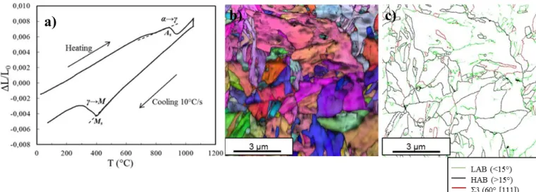
Dilatation curves attest to the obtaining of the three different microstructures. Indeed, one can see that the dilation during heating is the same for the three sample, with an austenitisation around 870°C (As). On the other
hand, significant changes are observables during cooling. On Fig. 3a, only the ferritic transformation (Fs) around
780°C is present. Fig. 4a shows that both ferritic and martensitic transformation occurred and their proportion can be graphically estimated comparing AB and BC segment. Here, the two segments are equal and thus the proportion (50-50%). Then, Fig.5a shows that only martensite is created from Ms temperature. All the grains
orientation maps show neither crystallographic texture nor morphologic texture, which confirmed the reset effect of the phase transformation during the heat treatment: the fiber α texture is erased. The recrystallized ferritic structure on Fig. 3b is composed of equiaxial grains about 10 micrometers large whereas the annealed martensitic structure (Fig. 5b), observed at higher magnification, show very thin tangled laths (up to 200 nm thick). Fig. 4b shows a microstructure with fine grains which is difficult to identify, even though the dilatation curve attests to a 50-50% dual phase structure. The understanding of this morphology will be discussed in the following. The grain boundaries misorientation maps have enabled to identify a typical characteristic of the martensitic transformation, the Σ3 boundary misorientation, corresponding to a rotation of 60° around the <111> axis between two grains. These grain boundaries are representing in red color. One can see that they are numerous in both dual-phase and martensitic structure but almost absent from the ferritic structure (Fig. 3c).
Figure 3: Dilation curve (a), Grain Orientation map (b) and Grain Boundaries Misorientation map (c) for the ferritic microstructure
Figure 4:Dilation curve (a), Grain Orientation map (b) and Grain Boundaries Misorientation map (c) for the dual-phase microstructure
Figure 5: Dilation curve (a), Grain Orientation map (b) and Grain Boundaries Misorientation map (c) for the martensitic microstructure
On Fig. 6, tensile tests performed at room temperature show a significant strain hardening. The yield strength increases upon increasing martensitic content and the total strain decreases. Due to the presence of very fine grains in martensite and larger grains in ferrite, the Hall-Petch
hardening effect can be claimed to explain this evolution. The fracture surfaces on the three microstructures shew numerous dimples (Fig. 7a-b), characteristic of a ductile behavior. One can attest of the strong relationship between microstructure and tensile properties at this temperature.
a)
b)
c)
a)
b)
c)
On one hand, mechanical resistances seem no more to be depending on the microstructure, particularly between the martensitic and the dual-phase sample where behaviors are very close from each other. In addition, the strain hardening is much less important at this temperature. On the other hand, the total strain of annealed martensite highly increases from 10 % to almost 30% whereas it remains the same that at room temperature for the ferrite, around 20%. Fracture surfaces analyses show dimpled features in the martensite (Fig. 7c) and in the dual-phase but intergranular decohesion areas in the ferrite (Fig. 7d).
Figure 6: Tensile properties of the microstructures created using the dilatometer
Figure 7: Fracture surfaces of tensile specimens
650°C. In the literature7, intergranular decohesion
mechanisms were already observed in ferritic ODS (14%Cr) steel above 600°C caused by cavities lining up along the grain boundaries.
II. C. Discussion
Regarding these mechanical tests, the martensitic structure seems to be the most optimized state for a tension sollicitation. In fact, it show the best resistance and a ductile behavior in the whole range of temperature. However, it can be noted that the presence of a certain amount of ferrite does not appear to be detrimendal for the mechanical resistance at 650°C. In order to evaluate the efficiency of controlled treatment into the dilatometer, tensile properties of the martensitic sample were compared to another ODS 9%Cr cladding tube studied at CEA8-10,
K30-M2, elaborated from the same powder, with the same chemical composition. Concerning this grade, the entire cladding tube was treated into a classical furnace (industrial treatment) after cold rolling and tensile specimens were machined afterwards. The same heat treatment than the K30-M1 was carried out but the cooling rate was of 70°C/min (about 1°C/s). This value is a parameter of the furnace and is not measured directly on the tube during the treatment. The microstructure of K30-M2 was observed and shew essentially laths of martensite. One should note that this grade have undergone a lower cooling rate under a less controlled atmosphere than the K30-M1 martensitic specimen prepared into the dilatometer. Despite these considerations, Fig. 8 shows that the yield strength of the K30-M1 grade (blue) at 650°C is about 60 MPa lower than the industrial grade (orange).
Figure 8: Yield strength comparison at 20°C and 650°C of different 9%Cr ODS steel cladding tubes investigated at CEA
To explain these results, a decarburization into the dilatometer during the austenitisation seemed to be the most probable hypothesis. In fact, observations on the
a)
b)
dual-phase cylindrical sample using MEB with the back-scattering electron detector shew only large grains of ferrite on the edge of the sample. It is well known that low carbon content promote growth of ferrite and thus increase the quench critical rates, which determine the formation domain of the different microstructures. Another effect of the carbon loss is the lower concentration of carbides formed during cooling, that are likely to reinforce the material.
The decarburization thickness can be estimated by calculating the diffusion length of carbon into the material. In first approximation, the diffusion coefficient of carbon within pure iron is used. At 1050°C, it is estimated to 3, 8.10-11 m2.s-1 (Ref. 11). Considering this approximation and
a diffusion time of 20 minutes, one obtains a diffusion length around 300µm. Knowing that the tensile specimens are only 500 µm thick, an important amount of carbon is likely to escape from the samples. To prevent this decarburization, a new heat treatment without austenitisation plateau was performed into the dilatometer to get an annealed martensitic microstructure. The more important carbon content in this sample compared to those with the initial treatment has been confirmed looking at the two martensitic start temperatures (Ms). On the dilatation
curves, one shows that the austenitisation plateau of the initial treatment induces a shift of Ms around 30°C toward
higher temperatures and it reaches 400°C (Fig.4a). The Andrews relation12 gives:
𝑀𝑠(°𝐶) = 539 − 423%𝐶 − 30,4%𝑀𝑛 − 17,7%𝑁𝑖
− 12,1%𝐶𝑟 − 11%𝑆𝑖 − 7%𝑀𝑜 Using this formula and the chemical composition of the material, one finds a carbon loss of approximatively 70% due to the austenitisation during 20 minutes at 1050°C. Therefore, one can see on Fig.8 that the new treatment induces higher mechanical properties for the annealed martensite (purple) than the initial one, particularly at 650°C where the yield strength reaches 325 MPa and is nearly equal to K30-M2, the industrial grade. This improvement of the mechanical properties between these two annealed martensitic sample shows that the carbides precipitation has a significant reinforcement role into the material. In addition, it has been previously mentionned that the carbon loss induces changes in the CCT diagramm. In this way, on further studies, treatments without plateau with different cooling rates will be carry out in order to reestimate the CCT of the K30-M1 ODS steel. In fact, it is probable that a cooling rate of 2°C/s (120°/min) would not induce a dual-phase structure but rather a martensitic structure, as it was observed on others 9%Cr ODS previously studied.
This investigation has shown that the dilatometer is a useful tool to applied controlled heat treatments and generate different microstructures. Nonetheless, because of the thin samples, decarburization is likely to rapidly occur
and needs to be control to avoid an heterogenous microstructure and a decrease of the mechanical properties.
III. MACROSCOPIC RESIDUAL STRESSES
RELAXATION
III.A. Experimental Procedure
The dilatometer has also been used to evaluate the efficiency of simple heat treatments on the relaxation of residual stresses. Both orthoradial and longitudinal macroscopic residual stresses have been sources of interest. The measurements were made with the calculation method proposed by Béchade et al.13, which uses the following
hypotheses: A transversal isotropic stresses state and a linear gradient of the stresses in the thickness of the tube as presented on Fig. 10 and 11. To perform this experiment, 9 mm long cylinders were cut into the as-rolling tube and heat to different temperatures (Tx on Fig.9) between 400°C
and 950°C. Then a very rapid quench (100°C/s) was applied to freeze the microstructure and thus the stress state.
Figure 9: Applied heat treatment
II.B.1.Orthoradial Stresses
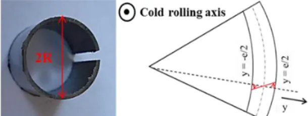
The orthoradial residual stresses were estimated by cutting the cylinder along the longitudinal direction. The measurement of the opening can give access to the maximal residual stress using the following formula10:
𝜎𝜃𝜃𝑚𝑎𝑥 = 𝐸.𝑒2. (𝑅1 0−
1
𝑅) (1)
Where E is the Young Modulus of the steel (225 GPa), e is the thickness of the tube, R0 is the radius before cutting and
R is the radius after cutting.
Two stripes were diametrically cut along the cylinder. The measurement of the spire enables the calculation of the maximal longitudinal residual stress4,10:
𝜎𝑧𝑧𝑚𝑎𝑥 = −𝑢(𝐿).𝐸𝐿2 ℎ
(2)
Where u(L) is the spire, L is the length of the stripes and h is the thickness of the tube.
Figure 11: Longitudinal stresses measurement
III.A. Results and Discussion
Fig. 12 shows the evolution of the macroscopic residual stresses into the tube during the heating. At room temperature longitudinal stresses are much more important than orthoradial stresses and almost reach 800 MPa. This value is not so far from the yield strength of the material and it shows the need to anneal these stresses. With increasing temperatures, both longitudinal and orthoradial stresses linearly decrease when the material is under the ferritic state. Then, the macroscopic residual stresses are almost annealed at the austenitisation start temperature (As), around 880°C. Therefore, one can conclude that the
phase transformation is not responsible for the relaxation of the first order residual stresses, which is an unexpected result according to the literature14 because the main
relaxation mechanism, the recrystallization, has not occurred yet. Indeed, one could have expected a plateau from room temperature to As and then a sharp decrease of
the residual stresses due to the phase transformation. To understand this phenomenon, further experiments using energetic X-ray would be necessary to obtain the entire residual stresses state and find out the relaxation mechanisms. In fact, different hypotheses could be considered such as small intragranular dislocations motions or rearrangements at interfaces and grains boundaries. It would also be interesting to perform this analytic
a phase transformation.
Figure 12: Macroscopic residual stresses evolution during the heat treatment
IV. CONCLUSION
The use of the quenched dilatometer has revealed to be an efficient analytic method to perform controlled treatment and generate different microstructures varying the cooling rates. In a first part, tensile tests have shown that the martensitic microstructure is the best compromise concerning yield strength and ductility in the whole temperature range even though the presence of ferrite does not induce an important decrease of the mechanical resistance at high temperature. EBSD analyses have shown that the good properties of the martensite can be correlated with the structure essentially composed of very thin laths that seem to increase the resistance at low temperature and prevent the material from intergranular damaging at 650°C. However, it should be taken into account that the use of the dilatometer gives rise to experimental limitation. In this study, decarburization was noticed and appears to be the main problem because of the material and the thin geometry of the samples. Thus, one should try to avoid as much as possible this decarburization that decreases the properties and can create heterogeneous microstructure. In this purpose, a new treatment without austenitisation plateau was proposed and shew encouraging results on the martensitic structure. Further experiments have to be performed applying other cooling rater in order to reestimate the CCT diagram of this material without the decarburization. Nevertheless, industrial treatment into furnace remains the best way to heat treat ODS steels in order to achieve high properties and homogenous microstructures.
In a second part, the dilatometer also allowed carrying out analytic treatments for the estimation of the macroscopic residual stresses. This experiment turns out to
provide good but quite unexpected results since the residual stresses linearly decrease during the heating and the phase transformation does not seem to influence their relaxation. Different mechanisms are suspected and it would be interesting to perform the same investigation on a ferritic 14%Cr ODS to compare the stresses relaxation of the two materials.
ACKOWLEGEMENT
The authors thank Jean-Luc Flament for the realisation of the mechanical test and Annick Bougault for her help to the interpretation of the fracture surfaces.
REFERENCES
1. Y. DE CARLAN et al., “CEA development of new ferritic ODS alloys for nuclear application”, J. Nucl.
Mater. , 386-388, 430-432 (2009).
2. P. DUBUISSON, Y. DE CARLAN, V. GARAT, M. BLAT, “ODS Ferritic/martensitic alloys for Sodium Fast Reactor fuel pin cladding”, J. Nucl. Mater. ,
428, 6-12 (2012).
3. J.S. BENJAMIN, “Dispersion strengthened superalloys by mechanical alloying”, Metall. Trans.,
Vol.1, 2943-2951 (1970).
4. L. TOUALBI, C. CAYRON, P. OLIER, R. LOGE, Y. DE CARLAN, “Relationships between mechanical behavior and microstructural evolutions in Fe 9Cr– ODS during the fabrication route of SFR cladding tubes”, J. Nucl. Mater. , 42, 410-416 (2013).
5. L. TOUALBI et al., “Assessment of a new fabrication
route for Fe–9Cr–1W ODS cladding tubes”, J. Nucl.
Mater. , 428, 47-53 (2012).
6. P. MOAYEART, Investigation of the martensitic transformation using dilatometry, Rapport CEA,
DEN/DANS/DMN/SRMA/LA2M (2013).
7. M. PRAUD, F. MOMPIOU, J. MALAPLATE, D.
CAILLARD, J. GARNIER, A. STECKMEYER, B. FOURNIER, “Study of the deformation mechanism in Fe-14% Cr ODS alloys”, J. Nucl. Mater. , 428, 90-97 (2012).
8. S. VINCENT, J. RIBIS, Caractérisations mécaniques
et microstructurales des aciers ODS CEA, Rapport
technique,
DEN/DANS/DMN/SRMA/LC2M&LA2M/NT/2013/3 393/A.
9. C. CAYRON, A. MONTANI, D. VENET, N. HERVE, Y. DE CARLAN, Caractérisation microstructurale
d’aciers ODS après mise en forme et après fluage,
Rapport technique DEHT/DL/2013/122.
10. L. TOUALBI, Optimisation de la gamme de
fabrication de tubes en aciers renforcés par dispersion nanométriques d’oxydes (ODS), PhD thesis,
CEMEF-Mines ParisTech (2012).
11. H. BAKKER et al., Landolt Borsntein, Diffusion in
Solid Metals and Alloy, Volume 26, p.481,
Springer-Verlag (1990)
12. C.Y. KUNG, J.J. RAYMENT, “An examination of the validity of existing empirical formulae for the calculation of Ms temperature”, Met. Trans. A., vol.
13A, 328-331 (1982).
13. J.L. BECHADE, L. TOUALBI, S. BOSONNET, “Macroscopic and microscopic determination of residual stresses in thin Oxides Dispersion Strengthened steel tubes”, Mater. Sci. Forum, 768-769, 296-303 (2014).
14. H.R.Z. SANDIM, R.A. RENZETTI, A.F. PADILHA, D. RAABE, M. KLIMENKOV, R. LINDAU, A. MOSLANG, “Annealing behavior of ferritic-martensitic 9%Cr-ODS-Eurofer steel”, Mater. Sci.