Abstract— Recently, modular powertrains have come under attentions in fuel cell vehicles to increase the reliability and efficiency of the system. However, modularity consists of hardware and software, and the existing powertrains only deal with the hardware side. To benefit from the full potential of modularity, the software side, which is related to the design of a suitable decentralized power allocation strategy (PAS), also needs to be taken into consideration. In the present study, a novel decentralized convex optimization (DCO) framework based on auxiliary problem principle (APP) is suggested to solve a multi-objective PAS problem in a modular fuel cell vehicle (MFCV). The suggested decentralized APP (D-APP) is leveraged for accelerating the computational time of solving the complex problem. Moreover, it enhances the durability and the robustness of the modular powertrain system as it can deal with the malfunction of the power sources. Herein, the operational principle of the suggested D-APP for the PAS problem is elaborated. Moreover, a small-scale test bench based on a light-duty electric vehicle is developed and several simulations and experimental validations are performed to verify the advantages of the proposed strategy compared to the existing centralized ones.
Index Terms— Fuel cell system, distributed optimization, fuel cell hybrid vehicle, energy management, multi-agent system.
I. INTRODUCTION
uel cell vehicles (FCVs) have become a propitious substitute for internal combustion engines (ICEs) to mitigate the greenhouse gas (GHG) emissions in transportation sector [1, 2]. Among several types of fuel cell (FC), proton exchange
membrane fuel cell (PEMFC) has been adopted broadly in green mobility thanks to its appropriate characteristics [3]. However, the use of a sole FC system (FCS) cannot satisfy all the requirements in vehicular applications as its performance is drastically declined in the presence of dynamic load profiles. Moreover, it is not able to capture the energy from regenerative braking owing to its energy storage incapability. Hence, hybridization of the FCS with other power sources, such as battery (B) or supercapacitor (SC), has been abundantly practiced in the literature to compensate for the mentioned weaknesses [4, 5].
In FCVs, the end-user cost is defined based on several factors, such as hydrogen consumption, FCS degradation, and battery unit degradation. To minimize this cost, it is required to define a well-developed multi-objective power allocation strategy (PAS). A variety of PASs, such as rule-based [6-8], equivalent consumption minimization [9, 10], model predictive control [11], adaptive [12, 13], dual-mode [14], and heuristic [15, 16], have been suggested in the past few decades for the FCVs. Some of these papers have also highlighted the possibility of integrating the prognostic and health management techniques into the design of PASs [17]. These techniques can be categorized into two main groups of model-based [18, 19], and data-driven [20, 21]. They are utilized to estimate the state of health (SOH) and remaining useful life (RUL) and then this estimation can be included as an input in the strategy to distribute the power. For the sake of combining the advantages of model-based and data-driven methods, a hybrid prognostic framework is introduced in [22]. The suggested method provides an uncertain characterization of RUL probability distribution. This method can be integrated into the existing PASs as a guiding principle for making appropriate sequential decisions to prolong the powertrain system lifetime. However, all the discussed strategies have been developed for single FCSs. Hence, they are very sensitive to the malfunction of the power sources, which is likely to happen in such a powertrain configuration.
In this respect, a new direction called modular energy systems (MESs) has come under attentions to overcome the limitations of a single FCS and increase reliability as well as the scalability of the FCVs [23]. Unlike the typical FCVs, a modular FCV (MFCV) is composed of a battery pack and a set of low-power FC modules, instead of a high-power one, to
Power Allocation Strategy based on
Decentralized Convex Optimization in Modular
Fuel Cell Systems for Vehicular Applications
Arash Khalatbarisoltani, Member, IEEE, Mohsen Kandidayeni, Member, IEEE,
Loïc Boulon, Senior
Member, Xiaosong Hu, Senior Member, IEEE
F
This work was supported in part by the Natural Sciences and Engineering Research Council of Canada (NSERC) and Canada Research Chairs program. The work of X. Hu was supported by the Chongqing Natural Science Foundation for Distinguished Young Scholars (Grant No. cstc2019jcyjjq0010), Chongqing Science and Technology Bureau, China.
(Corresponding authors: Loïc Boulon and Xiaosong Hu.)
A. Khalatbarisoltani, and L. Boulon are with the Hydrogen Research Institute, Department of Electrical and Computer Engineering, Université du Québec à Trois-Rivières, QC G8Z 4M3, Canada ([email protected], [email protected]). M. Kandidayeni is with e-TESC lab, Department of Electrical and Computer Engineering, Université de Sherbrooke, QC, Canada and also with Hydrogen Research Institute of Université du Québec à Trois-Rivières ([email protected]). X. Hu is with the State Key Laboratory for Mechanical Transmission, Department of Automotive Engineering, Chongqing University, Chongqing 400044, China and also with the Advanced Vehicle Engineering Centre, Cranfield University, Cranfield, MK43 0AL, UK ([email protected]).
Copyright (c) 2015 IEEE. Personal use of this material is permitted. However, permission to use this material for any other purposes must be obtained from the augment the reliability and the scalability characteristics.
Several PASs have been suggested for such modular systems, such as rule-based [24], hysteresis strategy [25], and droop control [26, 27]. In [28], Marx et al. have reported a comparative review of different concepts for these modular topologies in multi-stack FCs from a hardware point of view. They have concluded that the robustness is improved in parallel-connected configuration compared to other topologies. In [29], a PAS based on forgetting factor recursive least square is proposed for a MES composed of two 300-W PEMFC stacks with a parallel configuration. The strategy shows lower hydrogen consumption compared to average power and daisy chain algorithms. In [24], an adaptive state machine strategy is proposed for a MES composed of four 500-W PEMFCs and a battery pack. This strategy has improved the hydrogen economy compared to Daisy Chain and Equal distribution strategies while keeping the PEMFCs with the same health states.
Therefore, the hardware modularity has been already investigated in the MFCSs while the software modularity has escaped the attentions. Literature consideration shows that most of the existing PASs, regardless of having a modular or normal powertrain topology, are centralized. Therefore, they are very sensitive to a precipitous single point of failure through their powertrains from a software point of view. Moreover, the additional degrees of freedom in the MESs make the centralized algorithms substantially complicated and time-consuming to be solved. In this respect, some papers have focused on the distributed optimization algorithms to solve the PAS optimization problems [30-34]. In [30], a projected interior point method is proposed under the framework of model predictive control (MPC) to solve the power allocation problem and concluded that this strategy is faster than CVX tool, which is a general-purpose convex optimization software. In [31], CVX tool is utilized to solve a formulated convex optimization problem for a plug-in FCV, and it is shown that the proposed approach can effectively distribute the power between the power sources and also find the optimal sizes of each source. In [32], the slew rate of the PEMFC current and the battery state of charge (SoC) are considered to formulate the PAS in the form of quadratic programming (QP). Subsequently, a solver is utilized to solve the QP problem based on the alternating direction method of multipliers (ADMM). It is concluded that this approach is much faster than interior point or active set methods. In [33], a PAS for a hybrid electric vehicle is proposed based on ADMM and concluded that this strategy can achieve up to 90% of fuel saving obtained by dynamic programming (DP) while it is 3000 times faster than DP. In [34], a distributed optimization approach is put forward to solve the PAS of a hybrid vehicle. The comparison of this distributed algorithm with a centralized convex optimization problem shows that the proposed algorithm can result in the same fuel economy as the centralized method while its computational time is declined up to 1825 times. Although the discussed papers in [30-34] have improved the PAS formulation to a further step regarding the accuracy and computational time reduction, they are not still fully decentralized, and are sensitive to the occurrence of malfunction in their systems. In [35, 36], a decentralized approach based on non-cooperative game theory is proposed to formulate the PAS in a multi-source hybrid vehicle. The method in these papers shows a comparable performance to that
of the centralized strategies. Moreover, the potential of this approach for dealing with the sudden reconfigurations in the system is also demonstrated in [35]. However, this decentralized method is not able to deal with the constraints with a high amount of nonlinearity which are inevitable in FCVs.
In the light of the discussed papers, it can be stated that the design of MESs for a FCV application has gained considerable attentions. However, most of the existing works only deal with one side of modularity, either hardware or software. The hardware is related to the configuration of the powertrain (for instance a parallel multi-stack PEFMC system coupled with a battery pack), and the software is related to the development of a suitable PAS (like a decentralized algorithm). Furthermore, most of the papers which have focused on the software side are for hybrid electric vehicles with an ICE and not a FCV.
In this regard, this paper puts forward a decentralized convex optimization (DCO) methodology based on auxiliary problem principle (APP) [37-39] to solve a constrained convex approximation power distribution problem in a MFCV. This MFCV is composed of two PEMFCs, which are connected in parallel, and a battery pack. To the best of the authors’ prior knowledge, this is one of the first attempts, if any, to formulate an accelerated decentralized PAS for a MFCV to benefit from the full modularity potential considering hardware and software viewpoints. To this end, a multi-objective cost function, including the hydrogen consumption, battery SOC variation, PEMFC health state, and battery health state, is defined and minimized by the proposed decentralized APP (D-APP). To verify the performance of the suggested D-APP, it is compared with dynamic programming, which is an offline strategy, and an online centralized PAS based on sequential quadratic programming (SQP). Moreover, the performance of the D-APP has been justified by an experimental modular FC (MFC) test bench developed for the purpose of this work.
The rest of this paper is organized as follows. The powertrain and the modeling are detailed in section II. Section III formulates the convex PAS for a MFCV. The application of the D-APP is explained in section IV. Several numerical studies are given in section V. A real-time implementation via the developed small-scale MFC test bench is performed to confirm the effectiveness of the DCO in Section VI. Finally, conclusion and future directions are presented in Section VII.
II. MFCV POWERTRAIN CONFIGURATION AND MODELING A. Powertrain Structure and modeling
For the purpose of this study, a small-scale MFC test bench has been developed based on a low-speed vehicle called Nemo [40]. This test bench is presented in Fig. 1 and used for evaluating the performance of the proposed decentralized PAS. The MFC test bench is composed of two FC modules, a battery pack, a power supply, and a programmable load to emulate the prolusion system. The main device in each module is a 500-W FCS, a smoothing inductor, and a unidirectional DC-DC converter to control the current of the FCS. The powertrain is formulated as:
where 𝑃𝑚[𝑘] is the power of each FCS while 𝑀 = {1,2} is the
index of each FC module, 𝐷𝑚 is the duty cycle defined by
Fig.1. A MFC powertrain: a) schematic of powertrain, b) developed test bench.
each DCO-based control unit controller, 𝑃𝐵[𝑘] is the power of
the battery, 𝑃𝐿[𝑘] is the requested power from the propulsion
system, and 𝑘 is the index of time period. B. MFCS modeling and constraints
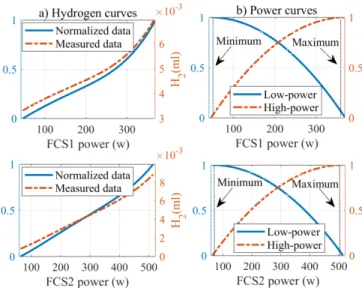
The FCSs are modeled as a voltage source by means of their static polarization curves which are validated by experimental tests, as shown in Fig. 2. The polarization curves of the employed FCSs are illustrated in Fig. 2a. Moreover, the power and hydrogen consumption curves of each utilized FCS are presented in Fig. 2b and Fig. 2c, respectively. Each FC has two fans which consume approximately 12 W. It is worth mentioning that the FCSs do not have the same performance as they have different ageing milestones.
To avoid FC degradation owing to the start-stop cycles and operation at open circuit voltage (OCV) within very low-power region, the requested power from the FCSs is supplied under some limitations. Equations (2.a) and (2.b) apply the FCSs’ power and slew rate limits, respectively.
Fig.2. The characteristics of the utilized 500-W FCSs, a) polarization curves, b) power curves, and c) hydrogen consumption curves.
𝑃𝑚,𝑚𝑖𝑛≤𝑃𝑚[𝑘]≤𝑃𝑚,𝑚𝑎𝑥, (2.a)
𝑅𝑑,𝑚𝛥𝑡 ≤ 𝑃𝑚[𝑘]-𝑃𝑚[𝑘 − 1]≤𝑅𝑢,𝑚𝛥𝑡, (2.b)
where 𝑃𝑚,𝑚𝑖𝑛 and 𝑃𝑚,𝑚𝑎𝑥 are the minimum and the
maximum power of the FCSs, 𝑅𝑑,𝑚 and 𝑅𝑢,𝑚 are the minimum
and the maximum slew rates, and 𝛥𝑡 is the time step duration. It should be noted that when the FCs go under degradation (which is a slow process), their rated power decreases. In this regard, the considered constraints regarding the minimum and maximum power of the PEMFC should be updated from time to time to keep the operation of the FCs within the safe and allowed zone [41].
C. Battery modeling and constraints
The battery pack which is passively linked to the DC bus is modeled by: 𝐼𝐵[𝑘] = 𝑢0[𝑘]−𝑅𝑠𝐼𝐵[𝑘]−𝑢𝐵[𝑘] 𝑅𝑐 + (3) 𝐶𝑐 𝑑 𝑑𝑡(𝑢0[𝑘] − 𝑅𝑠𝐼𝐵[𝑘] − 𝑢𝐵[𝑘]),
where 𝑢𝐵 and 𝐼𝐵 are the voltage and the current of the battery
unit, and 𝑢0 is the battery OCV. Technical description of the
battery system is given in Table I.
Equation (4.a) and (4.b) impose the power and the slew rate boundaries of the battery.
𝑃𝐵,𝑚𝑖𝑛≤ 𝑃𝐵[𝑘] ≤ 𝑃𝐵,𝑚𝑎𝑥, (4.a)
𝑅𝑑,𝐵𝛥𝑡 ≤ 𝑃𝐵[𝑘] − 𝑃𝐵[𝑘 − 1] ≤ 𝑅𝑢,𝐵𝛥𝑡, (4.b)
where 𝑃𝐵,𝑚𝑖𝑛 is the minimum battery power, 𝑃𝐵,𝑚𝑎𝑥 is the
battery maximum power, 𝑅𝑑,𝐵 is the falling slew rate, and 𝑅𝑢,𝐵 is the rising slew rate. Equation (5.a) presents the SoC limitations.
𝑆𝑜𝐶𝑚𝑖𝑛≤ 𝑆𝑜𝐶[𝑘] ≤ 𝑆𝑜𝐶𝑚𝑎𝑥, (5.a)
𝑆𝑜𝐶[𝑘 + 1] = 𝑆𝑜𝐶[𝑘] − 𝑃𝐵[𝑘]∆𝑡 𝑄𝐵𝑉𝐵[𝑘]3600,
(5.b)
𝑆𝑜𝐶[0] = 𝑆𝑜𝐶0, (5.c)
where 𝑆𝑜𝐶𝑚𝑖𝑛 and 𝑆𝑜𝐶𝑚𝑎𝑥 are the minimum and the
maximum limits of the 𝑆𝑜𝐶, and (5.b) denotes the SoC equation starting from 𝑆𝑜𝐶0 which is determined by (5.c). The service
life of battery unit is affected by the depth of discharge [42]. According to the manufacturer’s datasheet, when adopting the depth of discharge of 30%, the battery lifetime (𝑛𝐵) is equal
to the 80% of capacity fade. The battery’s state of health (𝑆𝑜𝐻𝐵)
is calculated by (6). 𝑆𝑜𝐻𝐵[𝑘 + 1] = 𝑆𝑜𝐻𝐵[𝑘] − |𝑃𝐵[𝑘]|∆𝑡 2𝑛𝐵𝑄𝐵𝑉𝐵[𝑘]3600, (6.a) 𝑆𝑜𝐻𝐵[0] = 𝑆𝑜𝐻𝐵,0, (6.b) 𝑆𝑜𝐻𝐵,𝑚𝑖𝑛≤ 𝑆𝑜𝐻𝐵[𝑘], (6.c)
where 𝑆𝑜𝐻 𝐵,𝑚𝑖𝑛 and 𝑆𝑜𝐻𝐵,0 denote the minimum and the
initial 𝑆𝑜𝐻 values, respectively.
D. Boost converter modeling and characteristics The DC-DC converters’ equations are as follows:
Copyright (c) 2015 IEEE. Personal use of this material is permitted. However, permission to use this material for any other purposes must be obtained from the 𝐿𝑚 𝑑 𝑑𝑡𝐼𝑚[𝑘] = 𝑉m[𝑘] − 𝑢ℎ,m[𝑘] − 𝑟𝐿𝑚𝐼m[𝑘], (7) {𝐼𝑢ℎ,m[𝑘] = 𝑚ℎ,m𝑉𝐵[𝑘] ℎ,m[𝑘] = 𝑚ℎ,m𝐼m[𝑘]𝜂ℎ,m𝑧 z= { 1 if 𝑃m> 0 −1 if 𝑃m< 0
where 𝑚ℎ,m is the modulation ration, 𝐼m is the FCs’ current, 𝑉m
is the FCs’ voltage, and 𝑉𝐵 is the battery pack voltage. The
technical parameters of the utilized DC-DC converters are given in Table II.
Table I
The battery pack parameters Variable Symbol Value Unit Series resistance 𝑅𝑠 0.0141 Ω
Capacity 𝑄𝐵 18.2 𝐴ℎ
Parallel capacitor 𝐶𝑐 1792 𝐹
Parallel resistance 𝑅𝑐 0.0177 Ω
Table II
Characteristics of the two boost converters Variable Symbol Value Inductor inductance 𝐿𝑚 1.2 mH
Inductor resistance 𝑟𝐿𝑚 23.7 mΩ
Average efficiency 𝜂ℎ,𝑚 95.7%
III. FORMULATION OF THE GENERAL PROBLEM
The multi-objective PAS problem for the considered MFCV is formulated as (8)–(12). Beside hydrogen consumption, the health limitations are normalized and added into the proposed cost function to extend the lifetime of the FCSs and the battery pack. The cost function (𝑠[𝑘]) takes into account four items and is calculated by:
𝑠[𝑘] = 𝑠ℎ,𝑚[𝑘] + 𝑠𝑑,𝑚[𝑘] + 𝑠𝐵[𝑘] + 𝑠𝑆𝑜𝐶[𝑘], (8)
where 𝑠ℎ,𝑚[𝑘] is the normalized hydrogen consumption cost
shaping function for each FCS, obtained by: 𝑠ℎ,𝑚[𝑘] =
ℎ𝑚[𝑘]−ℎ𝑚,𝑚𝑖𝑛 ℎ𝑚,𝑚𝑎𝑥−ℎ𝑚,𝑚𝑖𝑛 ,
(9) where ℎ𝑚[𝑘] is the hydrogen consumption, ℎ𝑚,𝑚𝑖𝑛 is the
minimum and ℎ𝑚,𝑚𝑎𝑥 is the maximum hydrogen consumption
of each FCS, as shown in Fig. 2c. The normalized FC degradation term (𝑠𝑑,𝐹𝐶𝑚[𝑘]) is defined by:
𝑠𝑑,𝐹𝐶𝑚[𝑘] = 𝛼𝑙𝑠𝑑,𝑚 𝑙 [𝑘] + 𝛼
ℎ𝑠𝑑,𝑚ℎ [𝑘], (10.a)
where 𝑠𝑑,𝑚𝑙 [𝑘] is the normalized degradation cost shaping term
related to low power operation, given by: 𝑠𝑑,𝑚𝑙 [𝑘] = 1 −
[𝑃𝑚[𝑘]−𝑃𝑚,𝑚𝑖𝑛]2 [𝑃𝑚,𝑚𝑎𝑥−𝑃𝑚,𝑚𝑖𝑛]2,
(10.b) 𝑠𝑑,𝑚ℎ [𝑘] is the normalized degradation cost shaping term related
to high power operation as: 𝑠𝑑,𝑚ℎ [𝑘] = 1 −
[𝑃𝑚[𝑘]−𝑃𝑚,𝑚𝑎𝑥]]2 [𝑃𝑚,𝑚𝑎𝑥−𝑃𝑚,𝑚𝑖𝑛]2,
(10.c)
𝛼𝑙 and 𝛼ℎ are the constant coefficients which are defined by:
𝛼𝑙= 𝜀𝑙 𝜀𝑙+𝜀ℎ, (10.d) 𝛼ℎ = 𝜀ℎ 𝜀𝑙+𝜀ℎ, (10.e) where 𝜀𝑙= 8.662 𝜇𝑉 ℎ⁄ and 𝜀ℎ=10 𝜇𝑉 ℎ⁄ are the low-power
and the high-power cell degradation rates [43, 44] . Fig.3 illustrates the measured and the normalized data of the hydrogen consumption beside the low-power and the high-power cost shaping functions. The normalized battery pack degradation function (𝑠𝐵[𝑘]) is calculated by:
𝑠𝐵[𝑘]= 𝑃𝐵[𝑘]
𝑃𝐿,𝑚𝑎𝑥 , (11)
where 𝑃𝐿,𝑚𝑎𝑥 is the maximum requested power.
Fig.3. a) The measured and normalized hydrogen consumption curves b) the low-power and the high-power cost shaping functions.
𝑠𝑆𝑜𝐶[𝑘] is a punishment term to try to maintain the SoC level
similar or near to its initial value (𝑆𝑜𝐶0).
𝑠𝑆𝑜𝐶[𝑘]=𝛽[𝑆𝑜𝐶[𝑘]-𝑆𝑜𝐶0], (12)
where 𝛽 is a big positive coefficient. The equality and inequality constraints are based on (1)-(2) and (4)-(6).
IV. DECENTRALIZED APP CONVEX ALGORITHM In this section, a detailed framework is presented to clarify the relaxation approach and the decentralized solution of the aforementioned optimization problem. In this algorithm, the PAS problem is decomposed into two individual subproblems where the output power of each FC module is the coupling variable and each of subproblems is assigned into one of the two FC modules. Then, the output power of each FC is duplicated into two new terms, real variable and virtual variable to mimic the rest of the powertrain system. The virtual variables are linked to each of the two subproblems. The local PAS subproblems are defined and formulated for each module, and an iterative procedure based on the decentralized APP approach
is carried out to coordinate between subproblems and seek the optimal operating point of the original modular powertrain system. At the end of each iteration, the local optimization algorithms based on the defined cost functions and constraints are used to calculate the real power of the local FC modules and the virtual power of the neighboring FC modules. These values are then sent to the neighboring FC modules. As each of the real and virtual variables are essential to have the same values once the APP approach is converged, equal constraints are used by the two local PASs restricting the error of the shared powers to be zero. If the calculated errors by the PAS modules and their duplicated ones are less than a predetermined level, the convergence is obtained. If not, a set of penalty multipliers (λ) are calculated and then the local PASs are solved again via the new variables. This algorithm is run repeatedly until it converges. Since the convergence speed of the algorithm is faster than the system dynamic, the virtual variables get very close to the real values, and this makes the final results be very close to the DP. It is worth noting that although the number of sharing variables increases the size of the matrixes, the decentralized forms are solved in a parallel manner which reduces the computational time. As shown in Fig.4, in the developed DCO-based algorithm, the general optimization problem with coupling constrains is decomposed into two sub-problems of 𝑀1 and 𝑀2. The battery pack is assumed to be
located in the shared area as a storage device and all of the FC modules are needed to be informed about the estimated SoC level. The equality constraints for 𝑀1can be formulated in
terms of 𝐹𝑀1(𝑎, 𝑏) = 0 and for 𝑀2by means of 𝐹𝑀2(𝑏, 𝑐) = 0.
In a similar way, the inequality constraints for 𝑀1 and 𝑀2 are
represented in the form of 𝐺1(𝑎, 𝑏) ≤ 0 and G2(b, c) ≤ 0,
respectively. By defining the two sets: 𝐴 =
{(𝑎, 𝑏): 𝐹𝑀1(𝑎, 𝑏) = 0, 𝐺𝑀1(𝑎, 𝑏) ≤ 0 } for 𝑀1 and 𝐵 = {(𝑏, 𝑐): 𝐹𝑀2(𝑏, 𝑐) = 0, 𝐺𝑀2(𝑏, 𝑐) ≤ 0 } for 𝑀2, the feasible response is a point (𝑎, 𝑏, 𝑐) that satisfies (𝑎, 𝑏) ∈ 𝐴 and (𝑏, 𝑐) ∈ 𝐵. Moreover, 𝑀1 and 𝑀2 have a vector (X,Y) with
regard to the data which need to be shared with the neighboring FC module, as shown in Fig.5. The vector X has the real FC
module power (𝑃𝑀11), and the virtual FC module power (𝑃𝑀 21), which is the 𝑀2 power in point of 𝑀1. The vector Y has the real
FC module power (𝑃𝑀 22) and the virtual FC module power (𝑃𝑀12), which is the 𝑀1 power in point of 𝑀2.
Fig. 4. The configuration of the D-APP PAS [45].
Fig.5. The APP steps a) defining the virtual modules b) duplicating the virtual modules.
By taking (8)-(12) into account, the cost of 𝑀1and 𝑀2
(𝐶𝑀[𝑘]) and the battery pack cost (𝐶𝐵[𝑘]) are separately defined
as:
𝐶M[𝑘] = sℎ,𝑚[𝑘] + s𝑑,𝑚[𝑘], (13.a)
𝐶𝐵[𝑘] = 𝑠𝐵[𝑘] + 𝑠𝑆𝑜𝐶[𝑘], (13.b)
Based on (13), the centralized optimization is reformulated by:
𝑚𝑖𝑛 {𝐶𝑀11{𝑃𝑀11[𝑘]}+ 𝐶𝑀22{𝑃𝑀22[𝑘]} + 𝐶𝐵{𝑃𝐵[𝑘]}}, (14) {𝑃𝑀11[𝑘], 𝑃𝑀12[𝑘]}ϵ A ,{𝑃𝑀12[𝑘], 𝑃𝑀22[𝑘]}ϵ 𝐵,
In order to solve the modified sub-problems, a regional decomposition framework based on APP approach is suggested in [37]. For the sake of relaxing the coupling between 𝑀1 and
𝑀2,𝑃𝑀𝑑𝑑− 𝑃𝑀𝑑𝑓= 0, d, 𝑓 = 1,2 𝑑 ≠f, and instead of applying standard Lagrangian technique, linearized augmented Lagrangian technique is applied to (14) to aid the convergence speed [38]. {𝑃𝑀11[𝑘], 𝑃𝑀21[𝑘], 𝑃𝑀12[𝑘], 𝑃𝑀22[𝑘]} = (15) 𝑚𝑖𝑛{𝐶𝑀11{𝑃𝑀11[𝑘]} + 𝐶𝑀22{𝑃𝑀22[𝑘]} + 𝐶𝐵{𝑃𝐵[𝑘]} +𝛽 2‖𝑃𝑀11[𝑘] − 𝑃𝑀12[𝑘]‖ 2 +𝛽 2‖𝑃𝑀22[𝑘] − 𝑃𝑀21[𝑘]‖ 2 : 𝑃𝑀11[k] − 𝑃𝑀12[k] = 0, 𝑃𝑀22[k] − 𝑃𝑀21[k] = 0}, {𝑃𝑀11[𝑘], 𝑃𝑀21[𝑘]}𝜖𝐴, {𝑃𝑀12[𝑘], 𝑃𝑀22[𝑘]}𝜖 𝐵,
The new quadratic function does not change the optimal result although the decomposition of the coupled C-PAS considerably improves the convergence speed [39].
A. Centralized APP
After applying the APP decomposition [37], (15) is solved by means of a sequence process. The suggested algorithm based
Copyright (c) 2015 IEEE. Personal use of this material is permitted. However, permission to use this material for any other purposes must be obtained from the on APP is formulated as follows:
{𝑃𝑀 𝑗+111[𝑘], PM 21 j+1 [𝑘], 𝑃𝑀𝑗+121[𝑘], 𝑃𝑀𝑗+122[𝑘]} = (16) min{𝐶𝑀1{𝑃𝑀11[𝑘]} + 𝐶𝑀22{𝑃𝑀22[𝑘]} + 𝐶𝐵{𝑃𝐵[𝑘]} +𝛽 2{𝑃𝑀11[𝑘]– 𝑃𝑀11 𝑗 [𝑘]}2 +𝛽 2{𝑃𝑀21[𝑘] − 𝑃𝑀21 𝑗 [𝑘]}2 +𝛽 2{𝑃𝑀12[𝑘] − 𝑃𝑀12 𝑗 [𝑘]}2 +𝛽 2{𝑃𝑀22[𝑘]– 𝑃𝑀22 𝑗 [𝑘]}2 +
𝜌
{𝑃𝑀11[𝑘] − 𝑃𝑀12[𝑘]}{𝑃𝑀11 𝑗 [𝑘]– 𝑃𝑀𝑗12[𝑘]} +𝜌
{𝑃𝑀22[𝑘] − 𝑃𝑀21[𝑘]}{𝑃𝑀22 𝑗 [𝑘]– 𝑃𝑀𝑗21[𝑘]} +𝜆1 𝑗 {𝑃𝑀11[𝑘] − 𝑃𝑀12[𝑘]} +𝜆2 𝑗 {𝑃𝑀22[𝑘] − 𝑃𝑀21[𝑘]}}, 𝜆1 𝑗+1 = 𝜆1 𝑗+ 𝛼{𝑃 𝑀11 𝑗+1 [𝑘]– 𝑃𝑀12 𝑗+1[𝑘]}, (17) 𝜆2𝑗+1= 𝜆2𝑗+ 𝛼{𝑃𝑀𝑗+122[𝑘]– 𝑃𝑀𝑗+121[𝑘]}, (18) where 𝑗 is the index of optimization iteration, and 𝛼, 𝛽, and 𝜌 are predefined positive values. The starting points 𝑃𝑀11, 𝑃𝑀21, 𝑃𝑀12, 𝑃𝑀22, and 𝜆 can be set as the prior answer or zero (cold start). 𝜆1,2𝑗
, as the Lagrange multipliers, are the estimated virtual FC module costs to keep the equality coupling constraints on the shared area at iteration 𝑗. The centralized APP utilizes the power values and the Lagrange parameters obtained from the previous step. It then alternates the achieved solutions of regional FC modules and updates the Lagrange multipliers. This iterative process will be completed if the stopping requirements are fulfilled.
B. Decentralized APP
With the aim of reducing the computational time and improving the fault-tolerant and the modularity features, (16)-(18) is divided into smaller subproblems for each autonomous FC module. The D-APP for the 𝑀1 is formulated by:
{𝑃𝑀11 𝑗+1 [𝑘], 𝑃𝑀21 𝑗+1[𝑘]} = (19) min{𝐶𝑀11{𝑃𝑀11[𝑘]}+𝐶𝐵{𝑃𝐵[𝑘]} +𝛽 2{𝑃𝑀11[𝑘]– 𝑃𝑀11 𝑗 [𝑘]} 2 +𝛽 2{𝑃𝑀21[𝑘] − 𝑃𝑀21 𝑗 [𝑘]} 2 +
𝜌
𝑃𝑀11[𝑘]{𝑃𝑀11 𝑗 [𝑘]– 𝑃𝑀𝑗12[𝑘]} −𝜌
𝑃𝑀21[𝑘]{𝑃𝑀22 𝑗 [𝑘]– 𝑃𝑀21 𝑗 [𝑘]} +𝜆1 𝑗 𝑃𝑀11[𝑘] − 𝜆2 𝑗 𝑃𝑀21[𝑘]}, 𝜆1 𝑗+1 = 𝜆1 𝑗+ 𝛼{𝑃 𝑀11 𝑗+1 [𝑘]– 𝑃𝑀12 𝑗+1[𝑘]}, (20) 𝜆2𝑗+1= λ2j+ 𝛼{𝑃𝑀 𝑗+121[𝑘]– 𝑃𝑀𝑗+122[𝑘]}, (21) The D-APP for the 𝑀2 is given by:{𝑃𝑀12 𝑗+1 [𝑘], 𝑃𝑀22 𝑗+1 [𝑘]} = (22) min{𝐶𝑀22{𝑃𝑀22[𝑘]} +𝐶𝐵{𝑃𝐵[𝑘]} +𝛽 2{𝑃𝑀22[𝑘] − 𝑃𝑀22 𝑗 [𝑘]}2+𝛽 2{𝑃𝑀12[𝑘] − 𝑃𝑀12 𝑗 [𝑘]}2 +
𝜌
𝑃𝑀22[𝑘]{𝑃𝑀22 𝑗 [𝑘]– 𝑃𝑀𝑗21[𝑘]} −𝜌
𝑃𝑀12[𝑘]{𝑃𝑀11 𝑗 [𝑘]– 𝑃𝑀𝑗12[𝑘]} −𝜆1𝑗𝑃𝑀12[𝑘]+𝜆2 𝑗 𝑃𝑀11[𝑘]}, 𝜆1𝑗+1= 𝜆1𝑗+ 𝛼{𝑃𝑀𝑗+112[𝑘]– 𝑃𝑀𝑗+111[𝑘]}, (23) 𝜆2𝑗+1= 𝜆2𝑗+ 𝛼{𝑃𝑀𝑗+122[𝑘]– 𝑃𝑀𝑗+121[𝑘]}, (24) These new modifications (19)-(21) and (22)-(24) basically lead to two D-APPs as a decentralized control layer, as shown in Fig.4. In [37], the APP parameters are defined based on:𝛼
=
1
2
𝛽= 𝜌
(25) It is worth mentioning that this parallel process will be stopped if the stopping conditions are satisfied. To better clarify the performance of the discussed method, a diagrammatic representation of the developed decentralized PAS layer is presented in Fig.6.
Fig.6. The general step-by-step flowchart of the D-APP strategy. V. COMPARISON AND RESULTS OF NUMERICAL CASE STUDIES
In this section, to have a comprehensive discussion, a number of important items are considered to elucidate the DCO-based PAS. An optimal PAS based on DP has been developed to serve as a baseline. Moreover, SQP, as a well-known centralized approach, is used to evaluate the performance of the proposed decentralized method.
The numerical studies have been tested via MATLAB. The calculation time depends on the utilized PC hardware (Processor= Core i5, 2.30 GHz, RAM= 4.00 GB). The total end-user cost, 𝑆𝑇, in USD, which includes five items is calculated
by:
𝑆𝑇 = 𝑆𝑆𝑜𝐶+ ∑ ∑ S𝐻,𝑚[𝑘] + S𝑑,𝑚[𝑘] + 𝑆𝐵[𝑘] 𝑚
𝑘
(26) The hydrogen cost (𝑆𝐻,𝑚[𝑘]), in USD, is computed by:
S𝐻,𝑚[𝑘] = H𝑚[𝑘]𝐶𝐻2∆𝑡, (27)
where 𝐻𝑚[𝑘] is the hydrogen consumption (per gram) and
𝐶𝐻2is the hydrogen price. The modules’ degradation cost (𝑆𝑑,𝑚[𝑘]), in USD, is calculated by:
S𝑑,𝑚[𝑘] = 𝑆𝑑,𝑚𝑙 [𝑘] + 𝑆𝑑,𝑚ℎ [𝑘], (28.a)
where 𝑆𝑑,𝑚𝑙 [𝑘] is the cost of low-power degradation and
𝑆𝑑,𝑚ℎ [𝑘] is the cost of high-power degradation, given by:
𝑆𝑑,𝑚𝑙 [𝑘] = 𝑛𝑚𝜀𝑙𝐶𝑚∆𝑡𝜇𝑙,𝑚 3600 𝑉𝑛,𝑚 , (28.b) 𝑆𝑑,𝑚ℎ [𝑘] = 𝑛𝑚𝜀ℎ𝐶𝑚∆𝑡𝜇ℎ,𝑚 3600 𝑉𝑛,𝑚 , (28.c) where 𝑛𝑚 is the cell numbers, 𝜀𝑙is the low power cell-level
degradation, 𝜀ℎ is the high power cell-level degradation, and
𝐶𝐹𝐶𝑚 is the FCS cost. 𝜇𝑙 and 𝜇ℎ are determined by:
𝜇𝑙,𝑚= { 1, If 𝑃𝑚𝑖𝑛,𝑚≤ 𝑃𝑚≤ 0.2𝑃𝑛𝑜𝑚,𝑚 0, otherwise (28.e) 𝜇ℎ,𝑚= { 1, If 0.8𝑃𝑛𝑜𝑚,𝑚≤ 𝑃𝑚≤ 𝑃𝑚𝑎𝑥,𝑚 0, otherwise (28.f) where 𝑉𝑛,𝑚 is the 10 % voltage drop of the nominal voltage of
each module. The cost of the battery unit degradation (𝑆𝐵[𝑘]),
in USD, is determined by:
𝑆𝐵[𝑘] = 𝐶𝐵{𝑆𝑜𝐻𝐵[𝑘] − 𝑆𝑜𝐻𝐵[0]} (29)
where 𝐶𝐵 is the battery pack price. The punishment term for the
battery pack (𝑆𝑆𝑜𝐶) in USD is calculated based on the price of
the hydrogen to recharge the battery unit at the end of the driving profile to reach the same level as the initial SoC. The battery pack is recharged by utilizing the FC stacks at their maximum efficiency points. This cost is added to the final end-user price. The reference price of the hydrogen, the FCS, and the battery pack are listed in Table. III.
Table. III
The reference price of hydrogen, battery, and FCS Cost Symbol Value Hydrogen 𝐶𝐻2 3.9254 $/Kg [46]
FCS 𝐶𝑚 35 $/kW [47]
Battery unit 𝐶𝐵 189 $/kWh [48]
A. Optimal power distribution under real driving pattern As shown in Fig.7, a real profile is herein considered. The power split based on DP, SQP, and DCO between the modules and the battery unit are shown in Fig. 8, Fig. 9, and Fig. 10, respectively, where Pload is the requested power, FC is the power provided by the modules, and Battery is the battery unit power. Fig. 8 demonstrates the performance of DP regarding the distribution of power and battery SoC. From this figure, it is seen that in the very beginning (0 to 25s), the FC modules recharge the battery. Then, from 25s to almost 140s, the FC modules operate in low power and battery SoC level decreases. From 140s on, the modules slightly recharge the battery to reach the same level of SoC as the initial one. In fact, knowing the driving cycle in advance makes DP have such a good performance. Fig. 9 illustrates the SQP strategy performance.
Fig.7. Six different analyses of the real cycle (a) the power, (b) the speed, (c) the power histogram, (d) the speed histogram.
Fig.8. The DP results under real driving profile: (a) power profiles, (b) the modules (𝑀1, 𝑀2) split powers, (c) the SoC.
Fig.9. The SQP results under real driving profile: (a) power profiles, (b) the modules (𝑀1, 𝑀2) split powers, (c) the SoC.
According to Fig. 9c, during the first 50s, this strategy tries to sustain the SoC level very close to 70 %. Afterwards. It fluctuates between charging and discharging and finishes almost with 71% of SoC. Fig. 10 presents the power distribution
Copyright (c) 2015 IEEE. Personal use of this material is permitted. However, permission to use this material for any other purposes must be obtained from the Fig.10. The APP results under real driving profile: (a) power profiles, (b) the
modules (𝑀1, 𝑀2) split powers, (c) the SoC.
obtained by the proposed decentralized strategy. From Fig. 10b, the modules largely operate at the efficient region to mitigate the degradation price, which leads to lower cost of degradation with the aid of battery power differences. Fig. 10c depicts the SoC level of the battery. The SoC fluctuates between 68.9% and 71.1%, less than approximately 2.2% variation. This strategy also manages to reach a very close SoC level to the initial one, as shown in Fig. 10c. The time series and the distribution of the real and the virtual FCSs’ power based on DCO are presented in Fig.11. It is evident that in both of the modules, the real and the virtual power are well-matched, and are almost located in the efficient region.
To evaluate the developed DCO-based method, the performance of the obtained results is compared with DP as an off-line optimization method and SQP as a centralized optimization algorithm. According to Table IV, the D-APP has achieved a near end-user price to DP (with 12% difference) while the computational burden is much less. Moreover, the
Fig.11. The profile and the distribution of the modules’ optimal powers (a) the power profile of the 𝑀1 (𝑀11: the real, 𝑀12: the virtual), (b) the distribution of
the 𝑀1. (c) the power profile of the 𝑀2 (𝑀22: the real, 𝑀21: the virtual), (d) the
distribution of the 𝑀2.
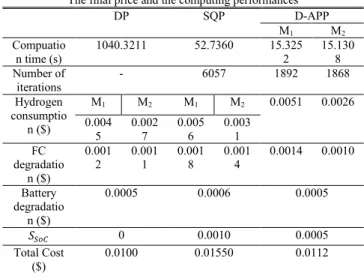
TABLE IV
The final price and the computing performances
DP SQP D-APP M1 M2 Compuatio n time (s) 1040.3211 52.7360 15.3252 15.1308 Number of iterations - 6057 1892 1868 Hydrogen consumptio n ($) M1 M2 M1 M2 0.0051 0.0026 0.004 5 0.0027 0.0056 0.0031 FC degradatio n ($) 0.001 2 0.0011 0.0018 0.0014 0.0014 0.0010 Battery degradatio n ($) 0.0005 0.0006 0.0005 𝑆𝑆𝑜𝐶 0 0.0010 0.0005 Total Cost ($) 0.0100 0.01550 0.0112
end-user price of D-APP is 27.74% lower than SQP while benefiting from a substantial decline in case of the computational time (71.31%) and the number of iterations (68.76 %). # denotes the number of iterations in the optimization algorithms (SQP, APP), and 𝑆𝑆𝑜𝐶 is the
punishment term to recharge the battery pack. Based on our experience, despite slight differences between the centralized APP (17)-(19) and the D-APP (20)-(25), the final results of both approaches are almost the same while the D-APP is faster. To have a clear understanding, here, the number of iterations and the computational time evaluation according to the 𝑀1 are
illustrated in Fig.12. It is evident that the computational time is related to the number of iterations.
Based on the obtained results, the decentralized method has less computational time which shows that this method is a reasonable and practical candidate in the real-time PAS optimization applications.
Fig.13 presents the price trajectories of different sources under a long test. The final end-user cost is approximately $0.2134, to which the total hydrogen price of $0.1033 contributes most (48.41% of the end-user expense). Between these two, the 𝑀1 with about $0.0641 (30.04% of the end-user
Fig.13. Optimal price trajectories: the total end-user, the hydrogen of 𝑀1, the
hydrogen of 𝑀2, the degradation of 𝑀1, and the degradation of 𝑀2, the battery
degradation.
cost) contributes more compared to the 𝑀1 with about $0.0392
(18.37% of the final cost). The second largest cost is the modules degradation cost of nearly $0.0330 (15.46% of the end-user cost). The battery degradation cost is around $0.0077 (3.61% of the final cost). It is the lowest cost, compared to the ones related to the modules. The punishment term to recharge the battery pack is approximately $0.0694 (32.52% of the final cost).
B. Impact of parameter tuning
The effect of tuning 𝜌 on the end-user price and the computational performance is scrutinized in this subsection. Fig.14 describes a detailed analysis of 𝜌 in a wide range, from 10 e-9 to 10 e+7. Fig. 14a shows the relation of 𝜌 with the final cost ($) and the computational time (s). In Fig. 14b, to verify that all the comparisons finish with the nearly same final state variable, the battery SoC evolution is presented. Fig. 14c shows a comparison between the computational complexity (s) and the number of iterations. It is apparent that they have the same pattern.
Generally, considering the modular powertrain problem and the hardware characteristics, 𝜌 shows a significant influence over the performance where an improper 𝜌 could lead to slower convergence and higher final cost. The end-user cost gradually
Fig.14. The investigation of the parameter ρ in the DCO performances.
decreases as 𝜌 grows. However, the computational complexity (s) becomes progressively heavy, particularly when 𝜌 exceeds 10 e-5. On the basis of our experience, 𝜌 in the range of 10 e-8 -10 e-7 is more suitable for the DCO problem and relying on our analyses, 𝜌=10e-7 is selected as the optimal value.
C. Sensitivity analysis
In this subsection, a sensitivity analysis of the proposed D-APP method with SQP is conducted. In this regard, different cost functions are taken into consideration: 1) hydrogen, 2) hydrogen and FCS degradation, 3) hydrogen, FCS and battery degradation. As shown in Fig.15, in case (2), the computational time of D-APP rises by almost 6.3378% in comparison with case (1) while the computational time of SQP increases by nearly 24.2079% compared to case (1). Moreover, the computational time of D-APP grows by around 10.5112 % in case (3), compared to case (1). However, in case (2), the computational time of SQP increases by approximately 62.4511 % compared to case (1). This analysis shows that D-APP has less sensitivity to a complex function with several constraints, which is important in practical real-time applications.
Fig.15. The comparison of the computational burdens. VI. EXPERIMENTAL IMPLEMENTATION
To verify the results, the D-APP has been implemented in the PAS layer of the developed scaled-down test bench via LabVIEW. As demonstrated in Fig.1.b, the test bench is equipped with two open-cathode 500-W HorizonTM PEMFCs
(𝑀1 and 𝑀2) and a battery unit, composed of six series 12-V,
18-Ah batteries. The voltage of 𝑀1 oscillates between 14.1 and
22.7 V, and the voltage of 𝑀2 varies between 14.5 and 23.4 V,
while the voltage of the DC-bus is given by the battery unit. The two boost converters are from Zahn ElectronicsTM. Each module has its PAS unit inside the National Instrument CompactRIO (NI 9022). The D-APP iteratively calculates the optimal references in parallel. The optimal reference of each module, 𝑃𝑅𝑒𝑓𝑀1 and 𝑃𝑅𝑒𝑓𝑀2, is updated at every control instant with
an interval of 10Hz. The results under the real profile is presented in Fig.16 and Fig.17. These results verify the validation of the real-time implementation of the D-APP as well as the correctness of the previous theoretical discussions.
Copyright (c) 2015 IEEE. Personal use of this material is permitted. However, permission to use this material for any other purposes must be obtained from the Fig.16. Optimal results under real driving profile via the developed test bench:
(a) power profiles, (b) the modules split powers, (c) the SoC.
Fig.17. The trajectories and the distribution of the power profiles. VII. CONCLUSION
In this paper, a DCO algorithm for MFCVs is suggested to address a multi-objective PAS optimization problem. In the proposed decentralized framework, a novel distributed normalized cost function, including hydrogen consumption and health-conscious constraints of the FC modules and the battery pack, is minimized via a fully D-APP algorithm. The effectiveness of the D-APP algorithm is validated via several numerical studies, such as the effect of parameter tuning and driving behavior. Moreover, the performance of the proposed approach is compared with DP strategy, as an off-line method, and SQP, as a centralized method. This comparison shows that D-APP is able to achieve an end-user price very near to DP while it is a real-time method. Moreover, compared to SQP, the decentralized method leads to less computational time and also provides less sensitivity in case of having complex function with several constraints. Finally, an experimental validation is performed on a developed test bench which justifies the effectiveness of the proposed D-APP.
Looking forward, a number of recommendations can be made to extend the contributions of this paper:
The proposed decentralized algorithm can be combined with an advanced MPC method to enhance the inherent robustness against uncertainty in both of vehicle model and projection of future driving conditions.
Another future direction can be integrating the proposed approach with advanced prognostic frameworks which consider variable loading condition to further prolong the lifetime of the power sources. In this work, the robustness and the modularity points
of view have not been demonstrated yet. Therefore, a comprehensive study regarding the raised matters will be performed in future.
REFERENCES
[1] S. F. Tie and C. W. Tan, "A review of energy sources and energy management system in electric vehicles," Renewable and
Sustainable Energy Reviews, vol. 20, pp. 82-102, 2013/04/01/ 2013.
[2] W. Su, H. Eichi, W. Zeng, and M. Chow, "A Survey on the Electrification of Transportation in a Smart Grid Environment,"
IEEE Transactions on Industrial Informatics, vol. 8, pp. 1-10, 2012.
[3] U. Eberle, B. Müller, and R. Helmolt, "Fuel cell electric vehicles and hydrogen infrastructure: Status 2012," Energy & Environmental
Science, vol. 5, pp. 8790-8798, 07/30 2012.
[4] B. Geng, J. K. Mills, and D. Sun, "Two-Stage Energy Management Control of Fuel Cell Plug-In Hybrid Electric Vehicles Considering Fuel Cell Longevity," IEEE Transactions on Vehicular Technology, vol. 61, pp. 498-508, 2012.
[5] H. B. Jensen, E. Schaltz, P. S. Koustrup, S. J. Andreasen, and S. K. Kaer, "Evaluation of Fuel-Cell Range Extender Impact on Hybrid Electrical Vehicle Performance," IEEE Transactions on Vehicular
Technology, vol. 62, pp. 50-60, 2013.
[6] S. Ziaeinejad, Y. Sangsefidi, and A. Mehrizi-Sani, "Fuel Cell-Based Auxiliary Power Unit: EMS, Sizing, and Current Estimator-Based Controller," IEEE Transactions on Vehicular Technology, vol. 65, pp. 4826-4835, 2016.
[7] D. Zhou, A. Al-Durra, F. Gao, A. Ravey, I. Matraji, and M. Godoy Simões, "Online energy management strategy of fuel cell hybrid electric vehicles based on data fusion approach," Journal of Power
Sources, vol. 366, pp. 278-291, 2017/10/31/ 2017.
[8] R. Wai, S. Jhung, J. Liaw, and Y. Chang, "Intelligent Optimal Energy Management System for Hybrid Power Sources Including Fuel Cell and Battery," IEEE Transactions on Power Electronics, vol. 28, pp. 3231-3244, 2013.
[9] Y. Yan, Q. Li, W. Chen, B. Su, J. Liu, and L. Ma, "Optimal Energy Management and Control in Multimode Equivalent Energy Consumption of Fuel Cell/Supercapacitor of Hybrid Electric Tram,"
IEEE Transactions on Industrial Electronics, vol. 66, pp.
6065-6076, 2019.
[10] E. Tazelaar, B. Veenhuizen, P. vandenBosch, and M. Grimminck, "Analytical Solution of the Energy Management for Fuel Cell Hybrid Propulsion Systems," IEEE Transactions on Vehicular
Technology, vol. 61, pp. 1986-1998, 2012.
[11] X. Hu, C. Zou, X. Tang, T. Liu, and L. Hu, "Cost-optimal energy management of hybrid electric vehicles using fuel cell/battery health-aware predictive control," ieee transactions on power
electronics, pp. 1-1, 1/1/2019 2019.
[12] J. Chen, C. Xu, C. Wu, and W. Xu, "Adaptive Fuzzy Logic Control of Fuel-Cell-Battery Hybrid Systems for Electric Vehicles," ieee
transactions on industrial informatics, vol. 14, pp. 292-300,
1/1/2018 2018.
[13] C. Wu, J. Chen, C. Xu, and Z. Liu, "Real-Time Adaptive Control of a Fuel Cell/Battery Hybrid Power System With Guaranteed Stability," IEEE Transactions on Control Systems Technology, vol. 25, pp. 1394-1405, 2017.
[14] X. Meng, Q. Li, G. Zhang, T. Wang, W. Chen, and T. Cao, "A Dual-Mode Energy Management Strategy Considering Fuel Cell Degradation for Energy Consumption and Fuel Cell Efficiency Comprehensive Optimization of Hybrid Vehicle," IEEE Access, vol. 7, pp. 134475-134487, 2019.
[15] M. G. Carignano, V. Roda, R. Costa-Castelló, L. Valino, A. Lozano, and F. Barreras, "Assessment of energy management in a fuel cell/battery hybrid vehicle," ieee access, vol. 7, pp. 16110-16122, 1/1/2019 2019.
[16] N. Sulaiman, M. A. Hannan, A. Mohamed, E. H. Majlan, and W. R. Wan Daud, "A review on energy management system for fuel cell hybrid electric vehicle: Issues and challenges," Renewable and
Sustainable Energy Reviews, vol. 52, pp. 802-814, 2015/12/01/
2015.
[17] M. Yue, S. Jemei, R. Gouriveau, and N. Zerhouni, "Review on health-conscious energy management strategies for fuel cell hybrid electric vehicles: Degradation models and strategies," International
Journal of Hydrogen Energy, vol. 44, pp. 6844-6861, 2019/03/08/
2019.
[18] M. Jouin, R. Gouriveau, D. Hissel, M.-C. Péra, and N. Zerhouni, "Prognostics of PEM fuel cell in a particle filtering framework,"
International Journal of Hydrogen Energy, vol. 39, pp. 481-494,
2014/01/02/ 2014.
[19] E. Lechartier, E. Laffly, M.-C. Péra, R. Gouriveau, D. Hissel, and N. Zerhouni, "Proton exchange membrane fuel cell behavioral model suitable for prognostics," International Journal of Hydrogen
Energy, vol. 40, pp. 8384-8397, 2015/07/13/ 2015.
[20] R. E. Silva, R. Gouriveau, S. Jemeï, D. Hissel, L. Boulon, K. Agbossou, et al., "Proton exchange membrane fuel cell degradation prediction based on Adaptive Neuro-Fuzzy Inference Systems,"
International Journal of Hydrogen Energy, vol. 39, pp.
11128-11144, 2014/07/15/ 2014.
[21] K. Javed, R. Gouriveau, N. Zerhouni, and D. Hissel, "Prognostics of Proton Exchange Membrane Fuel Cells stack using an ensemble of constraints based connectionist networks," Journal of Power
Sources, vol. 324, pp. 745-757, 2016/08/30/ 2016.
[22] Y. Cheng, N. Zerhouni, and C. Lu, "A hybrid remaining useful life prognostic method for proton exchange membrane fuel cell,"
International Journal of Hydrogen Energy, vol. 43, pp.
12314-12327, 2018/07/05/ 2018.
[23] A. K. Soltani, M. Kandidayeni, L. Boulon, and D. L. St-Pierre, "Modular Energy Systems in Vehicular Applications," Energy
Procedia, vol. 162, pp. 14-23, 2019/04/01/ 2019.
[24] A. O. M. Fernandez, M. Kandidayeni, L. Boulon, and H. Chaoui, "An Adaptive State Machine Based Energy Management Strategy for a Multi-Stack Fuel Cell Hybrid Electric Vehicle," IEEE
Transactions on Vehicular Technology, pp. 1-1, 2019.
[25] H. Zhang, X. Li, X. Liu, and J. Yan, "Enhancing fuel cell durability for fuel cell plug-in hybrid electric vehicles through strategic power management," Applied Energy, vol. 241, pp. 483-490, 2019/05/01/ 2019.
[26] T. Wang, Q. Li, H. Yang, L. Yin, X. Wang, Y. Qiu, et al., "Adaptive current distribution method for parallel-connected PEMFC generation system considering performance consistency," Energy
Conversion and Management, vol. 196, pp. 866-877, 2019/09/15/
2019.
[27] Q. Li, T. Wang, C. Dai, W. Chen, and L. Ma, "Power Management Strategy Based on Adaptive Droop Control for a Fuel Cell-Battery-Supercapacitor Hybrid Tramway," IEEE Transactions on Vehicular
Technology, vol. 67, pp. 5658-5670, 2018.
[28] N. Marx, L. Boulon, F. Gustin, D. Hissel, and K. Agbossou, "A review of multi-stack and modular fuel cell systems: Interests, application areas and on-going research activities," International
Journal of Hydrogen Energy, vol. 39, pp. 12101-12111, 2014/08/04/
2014.
[29] T. Wang, Q. Li, L. Yin, and W. Chen, "Hydrogen consumption minimization method based on the online identification for multi-stack PEMFCs system," International Journal of Hydrogen Energy, vol. 44, pp. 5074-5081, 2019/02/26/ 2019.
[30] S. East and M. Cannon, "Energy Management in Plug-In Hybrid Electric Vehicles: Convex Optimization Algorithms for Model Predictive Control," ieee transactions on control systems and
technology, pp. 1-13, 1/1/2019 2019.
[31] X. Wu, X. Hu, X. Yin, L. Li, Z. Zeng, and V. Pickert, "Convex programming energy management and components sizing of a
plug-in fuel cell urban logistics vehicle," Journal of Power Sources, vol. 423, pp. 358-366, 2019/05/31/ 2019.
[32] H. Chen, J. Chen, Z. Liu, and H. Lu, "Real‐time optimal energy management for a fuel cell/battery hybrid system," asian journal of
control, vol. 21, pp. 1847-1856, 7/1/2019 2019.
[33] S. East and M. Cannon, "Fast Optimal Energy Management With Engine On/Off Decisions for Plug-in Hybrid Electric Vehicles," presented at the IEEE Control Systems Letters, 2019.
[34] T. C. J. Romijn, M. C. F. Donkers, J. T. B. A. Kessels, and S. Weiland, "A Distributed Optimization Approach for Complete Vehicle Energy Management," IEEE Transactions on Control
Systems Technology, vol. 27, pp. 964-980, 2019.
[35] H. Yin, C. Zhao, and C. Ma, "Decentralized Real-Time Energy Management for a Reconfigurable Multiple-Source Energy System," ieee transactions on industrial informatics, vol. 14, pp. 4128-4137, 9/1/2018 2018.
[36] H. Yin, C. Zhao, M. Li, C. Ma, and M.-Y. Chow, "A Game Theory Approach to Energy Management of An Engine– Generator/Battery/Ultracapacitor Hybrid Energy System," ieee
transactions on industrial electronics, vol. 63, pp. 4266-4277,
7/1/2016 2016.
[37] B. H. Kim and R. Baldick, "Coarse-grained distributed optimal power flow," IEEE Transactions on Power Systems, vol. 12, pp. 932-939, 1997.
[38] D. Hur, J. Park, and B. H. Kim, "Evaluation of convergence rate in the auxiliary problem principle for distributed optimal power flow,"
IEE Proceedings - Generation, Transmission and Distribution, vol.
149, pp. 525-532, 2002.
[39] G. Cohen, "Auxiliary problem principle and decomposition of optimization problems," Journal of Optimization Theory and
Applications, vol. 32, pp. 277-305, November 01 1980.
[40] F. Martel, S. Kelouwani, Y. Dubé, and K. Agbossou, "Optimal economy-based battery degradation management dynamics for fuel-cell plug-in hybrid electric vehicles," Journal of Power Sources, vol. 274, pp. 367-381, 2015/01/15/ 2015.
[41] M. Kandidayeni, A. O. M. Fernandez, A. Khalatbarisoltani, L. Boulon, S. Kelouwani, and H. Chaoui, "An Online Energy Management Strategy for a Fuel Cell/Battery Vehicle Considering the Driving Pattern and Performance Drift Impacts," IEEE
Transactions on Vehicular Technology, vol. 68, pp. 11427-11438,
2019.
[42] S. Ebbesen, P. Elbert, and L. Guzzella, "Battery state-of-health perceptive energy management for hybrid electric vehicles," IEEE
Transactions on Vehicular technology, vol. 61, pp. 2893-2900,
2012.
[43] H. Chen, P. Pei, and M. Song, "Lifetime prediction and the economic lifetime of Proton Exchange Membrane fuel cells,"
Applied Energy, vol. 142, pp. 154-163, 2015/03/15/ 2015.
[44] N. Herr, J.-M. Nicod, C. Varnier, L. Jardin, A. Sorrentino, D. Hissel,
et al., "Decision process to manage useful life of multi-stacks fuel
cell systems under service constraint," Renewable Energy, vol. 105, pp. 590-600, 2017/05/01/ 2017.
[45] A. Khalatbarisoltani, L. Boulon, D. L. St-Pierre, and X. Hu, "Decentralized Implementation of an Optimal Energy Management Strategy in Interconnected Modular Fuel Cell Systems," in 2019
IEEE Vehicle Power and Propulsion Conference (VPPC), 2019, pp.
1-5.
[46] S. Satyapal, "US Department of energy hydrogen and fuel cell technology overview," Presented at The 14th International
Hydrogen and Fuel Cell Expo (FC EXPO 2018), 2018.
[47] USDRIVE, "Fuel Cell Technical Team Roadmap," 2017. [48] K. Mongird, V. V. Viswanathan, P. J. Balducci, M. J. E. Alam, V.
Fotedar, V. S. Koritarov, et al., "Energy Storage Technology and Cost Characterization Report," Pacific Northwest National Lab.(PNNL), Richland, WA (United States)2019.
Copyright (c) 2015 IEEE. Personal use of this material is permitted. However, permission to use this material for any other purposes must be obtained from the
Arash Khalatbarisoltani (S’18) received the master’s
degree in mechatronics from Arak University, Arak, Iran, in 2016. He is currently working toward the Ph.D. degree with the Hydrogen Research Institute (IRH) and the Department of Electrical and Computer Engineering, Université du Québec à Rivières (UQTR), Trois-Rivières, QC, Canada. His research interests include optimal control, decentralized systems, fuel cell systems, energy management, renewable energy, and intelligent transport systems. He had three years’ research experience, especially in renewable vehicles and fuel cell systems. He published seven scientific papers in SCI journals such as IEEE Transactions on Vehicular Technology, Energy Procedia, and Energy. He presented his research works in several international conferences such as the IEEE Vehicle Power and Propulsion Conference (VPPC), International Conference on Fundamentals & Development of Fuel Cells (FDFC). He received the excellent student scholarship of Université du québec à Trois-rivières for his Ph.D. program. He is a reviewer in multiple high impact factor SCI journals, selectively including IEEE Transactions on Vehicular Technology, Renewable & Sustainable Energy Reviews, IEEE Access, Applied Energy and IET Electrical Systems in Transportation. He did an internship at Chongqing Automotive Collaborative Innovation Center, Chongqing University in China under supervising of Prof. Xiaosong Hu.
Mohsen Kandidayeni (S’18) was born in Tehran (Iran) in 1989. His educational journey has spanned through different paths. He received the B.S. degree in Mechanical Engineering in 2011, and then did a master’s degree in Mechatronics at Arak University (Iran) in 2014. He joined the Hydrogen Research Institute of University of Quebec, Trois-Rivières (UQTR), QC, Canada, in 2016 and received his Ph.D. degree in Electrical Engineering from this university in 2020. He is currently a postdoctoral researcher in electric-Transport, Energy Storage and Conversion Lab (e-TESC) at Université de Sherbrooke and a research assistant member in Hydrogen Research Institute of UQTR. He was a straight-A student during his Master and Ph.D. programs. Moreover, he has been the recipient of several awards/honors during his educational path, such as a doctoral scholarship from the Fonds de recherche du Québec–Nature et technologies (FRQNT), a postdoctoral scholarship from FRQNT, an excellence student grant from UQTR, and the 3rd prize in Energy Research Challenge from the Quebec Ministry of Energy and Natural Resources. He has been actively involved in conducting research through authoring, coauthoring, and reviewing several papers in different prestigious scientific journals and also participating in various international conferences. His research interests include energy-related topics, such as hybrid electric vehicles, fuel cell systems, energy management, Multiphysics systems, modeling, and control.
Loïc Boulon (M'10, SM'15) received the master degree in
electrical and automatic control engineering from the University of Lille (France), in 2006. Then, he obtained a PhD in electrical engineering from University of Franche-Comté (France). Since 2010, he is a professor at UQTR (Full Professor since 2016) and he works into the Hydrogen Research Institute (Deputy director since 2019). His work deals with modeling, control and energy management of multiphysics systems. His research interests include hybrid electric vehicles, energy and power sources (fuel cell systems, batteries, and ultracapacitors). He has published more than 120 scientific papers in peer-reviewed international journals and international conferences and given over 35 invited conferences all over the word. Since 2019, he is the world most cited authors of the topic "Proton exchange membrane fuel cells (PEMFC); Fuel cells; Cell stack" in Elsevier SciVal. In 2015, Loïc Boulon was general chair of the IEEE-Vehicular Power and Propulsion Conference in Montréal (QC, Canada). Prof. Loïc Boulon is now VP-Motor Vehicles of the IEEE Vehicular Technology Society and he found the "International Summer School on Energetic Efficiency of Connected Vehicles" and the "IEEE VTS Motor Vehicle Challenge". He is the holder of the Canada Research Chair in Energy Sources for the Vehicles of the future.
Xiaosong Hu (SM’16) received the Ph.D. degree in automotive engineering from the Beijing Institute of Technology, Beijing, China, in 2012. He did scientific research and completed the Ph.D. dissertation in Automotive Research Center at the University of Michigan, Ann Arbor, MI, USA, between 2010 and 2012. He is currently a Professor with the State Key Laboratory of Mechanical Transmissions and at the Department of Automotive Engineering, Chongqing University, Chongqing, China. He was a Postdoctoral Researcher with the Department of Civil and Environmental Engineering, University of California, Berkeley, CA, USA, between 2014 and 2015, as well as at the Swedish Hybrid Vehicle Center and the Department of Signals and Systems at Chalmers University of Technology, Gothenburg, Sweden, between 2012 and 2014. He was also a Visiting Postdoctoral Researcher with the Institute for Dynamic Systems and Control at Swiss Federal Institute of Technology (ETH), Zurich, Switzerland, in 2014. His research interests include modeling and control of alternative powertrains and energy storage systems. Dr. Hu was the recipient of several prestigious awards/honors, including Emerging Sustainability Leaders Award in 2016, EU Marie Currie Fellowship in 2015, ASME DSCD Energy Systems Best Paper Award in 2015, and Beijing Best Ph.D. Dissertation Award in 2013.
![Fig. 4. The configuration of the D-APP PAS [45].](https://thumb-eu.123doks.com/thumbv2/123doknet/14604919.731660/5.918.518.799.76.365/fig-configuration-d-app-pas.webp)