In October 2016, an international challenge devoted to the energy management of a fuel cell/battery vehicle was launched during the 2016 IEEE Vehicle Power and Propulsion Conference (VPPC), in Hangzhou, China. The vehicle driving cost, which includes the hydrogen and the source degradation costs, was used as a base of comparison. Following the success of this first initiative, this paper analyses the best participant energy managements. It appeared that well designed Energy Management Strategies (EMS) lead to reduce significantly the trip cost while ill-designed EMS may lead to high fuel consumption or premature source degradations. Tight deadlines have deliberately limited the development times, but the best results are close to the theoretical dynamic programming optimum. Knowing in advance the mission profile also does not appears so important because the best developed strategies have quite similar results than for the dynamic programing optimal strategy.
A complex system
The increase in the average temperature of the planet has been observed since the industrial era. Transport contributes significantly to climate change. The greenhouse gases created by the burning of fossil fuels activate this phenomenon. In 50 years, the number of cars could increase by 160 % [1], [2]. The International Energy Agency (IEA) thus calls for a 60 % reduction in transport emissions in 2050 compared to 1990 to limit the rise in temperature to 2 °C compared to the pre-industrial era. Cleaner means of transport must be offered. Electric, hybrid and Fuel Cell vehicles are developing to face this challenge [2]. Electric vehicles have a limited range and long charging time. Hybrid vehicles yet require fossil fuel. Fuel cell vehicles are based on hydrogen as energy source. As hydrogen can be produced by the electrolysis of water, this energy could be “clean” and sustainable. However, the electric production has also to be considered.
Today, FC vehicles appear in the automotive market (e.g. Toyota, Honda and Hyundai) due to some advantages. For an equivalent energy storage mass, the autonomy of a fuel cell
vehicle (FCV) is higher than a battery electric vehicle (BEV) one. With a full tank of H2, a driver can expect to travel about 500 km (310 mi), against 200 km (130 mi) for an electric car and 1,000 km (620 mi) for a conventional thermal vehicle. However, even if the energy density of hydrogen is high (33.3 kWh/kg), the current hydrogen storage capacities are limited (generally 5.5 kg of H2 pressurized at 700 bar) [3]. Moreover, the hydrogen tank fills up in a few minutes in station whereas a full charge of a battery electric vehicle lasts several hours. However, FCVs have to face some issues. The FC converts the chemical hydrogen energy into electrical energy to supply an electric traction motor. However, fast power transients can lead to a gas starvation, which will permanently damage the FC [4]. The traction of a vehicle requires high power dynamics, which is harmful to the FC. Furthermore, the energy flow of FC systems is unidirectional, which does not allow recovering braking energy [5]. Batteries can then be used as a secondary source to handle the power transients and to recover braking energy. This secondary source allows extending the FC lifetime and reduces its related cost. In this way, Toyota uses a 1.6 kWh nickel-metal hydride (NiMh) battery to assist the 114 kW FC in its Mirai car [6]. Similarly, lithium batteries supply the Honda FCX Clarity or the Hyundai Tucson FCEV [7], [8].
The FC/battery vehicle represents a complex system. Its control can be organized in two parts: the local control and the Energy Management Strategy (EMS) (figure 1). The local control aims to tune the variables of each subsystem (light blue blocks in figure 1). The EMS aims to distribute the energy between the subsystems from the driver requests (dark blue block in figure 1). The EMS leads to the references of the local control. The vehicle performances are then dependent on the target objectives, e.g. the reduction of the fuel consumption. Thus, the EMS appears as a key element in the operation of a FC/battery vehicle. The EMS determines the distribution of the energy flows between the energy sources according to a vehicle mission profile and the technical specifications of the sources (green oval pictograms in figure 1).
IEEE VTS Motor Vehicle Challenge
2017
Fuel Cell/Battery Vehicle Energy
Management – Key Issues
Clément Dépature1, Samir Jemeï2, Loïc Boulon1, Alain Bouscayrol3, Neigel Marx2, Simon Morando2, Ali Castaings3 1 Université du Québec à Trois-Rivières, 2 University of. Bourgogne Franche-Comté, 3 University of Lille 1, POSTPRINT VERSION. The final version is published here:
Depature, C., Jemei, S., Boulon, L., Bouscayrol, A., Marx, N., Morando, S., & Castaings, A. (2018). Energy management in fuel-cell\/battery vehicles: Key issues identified in the ieee vehicular technology society motor vehicle challenge 2017. IEEE Vehicular Technology Magazine, 13(3), 144-151.
http://dx.doi.org/10.1109/MVT.2018.2837154
© 2018 IEEE. Personal use of this material is permitted. Permission from IEEE must be obtained for all other uses, in any current or future media, including reprinting/republishing this material for advertising or promotional purposes, creating new collective works, for resale or redistribution to servers or lists, or reuse of any copyrighted component of this work in other works.
multi-source system local control driver requirements
Energy Management Strategy
strategy inputs from specifications source 1 source 2 source n
subsystem 1 subsystem 2 subsystem n controller 1 controller 2 controller n
Figure 1 Multi-source system management
Motivation
Over the last 10 years, several works have been devoted to the energy management of FC/battery vehicles. For example, over the period from January 1, 2007 to May 1, 2017, IEEE Xplore identifies 54 journals and magazines, and 309 conference papers on this subject (keywords: battery, fuel cell, management, vehicle). Minimization of fuel consumption, maximal efficiency or maximal power identification, degradation or cost minimization are used as criteria to build EMS. For multi-source vehicles, EMS can be distinguished: heuristic and optimal strategies [9]. Heuristic strategies rely on rules based on human expertise and depending on strategy inputs. Optimization-based strategies mathematically defined specifications in a cost function to reach an optimal behavior for a specific driving cycle. However, optimization-based strategies cannot be used in real time because they need long computation time and the considering driving cycle must be known in advance.
Based on fuel consumption or source degradations arguments, different works propose ad hoc strategies for energy management of FC/battery vehicles. However, it is difficult to compare the performance and effectiveness of these EMSs without a common subject and criteria. In this way, an international challenge was recently created to compare different strategies for a FC/battery vehicle [10]. Within the framework of this challenge, a complete vehicle model and the associated local control were provided. The participants had to design the EMS. However, in order to consider a realistic driving application, the knowledge of the scoring driving cycle was not known beforehand and off-line optimal strategies were forbidden. The developed EMS should be designed to minimize two important aspects identified in the literature: the fuel consumption and the energy source degradations. An equivalent global cost function $global (in US$) was defined to combine the consumption and the degradation criteria. The global trip cost $global then serves as a common criterion to
compared the developed participants EMSs. The aim of this challenge was then to develop a robust on-line EMS to:
1 Increase the FC lifetime which depends on the FC
power operation and start/stop events. During a trip, the cost of the FC system degradation $Δfc is calculated depending on a degradation function Δfc and the FC system cost.The complete model of the degradation and cost functions are detailed in [10].
2 Minimize the hydrogen consumption which is a
function of the FC current. Considering the H2 price, the trip cost $H2 is calculated considering the total fuel consumption.
3 Limit the battery State of Charge (SoC). The battery
degradation Δbat depends on its SoC and on the power transients. For example, high currents in the battery reduce its lifetime. The battery system degradation cost $Δbat is then calculated from Δbat and the initial battery cost.
Depending on the battery SoC at the end of the driving cycle, a battery charge penalty is finally set up. In this way, the battery is full charged at the best FC efficiency point at the end of a driving cycle. This consider the related additional H2 consumption and the
FC and the battery degradations. The cost of this recharge $charge is then taken into account for the global
cost function definition $global:
charge 2 $ $ $ $ $global fc H bat Realization
The studied vehicle traction is based on the commercial Tazzari Zero battery Electric Vehicle (EV) [11] (figure 2). The studied FC/battery vehicle is composed of a 15 kW induction machine fed by a voltage-source-inverter through the ESS, composed of a Lithium Iron Phosphate (LiFePO4) battery pack, a Proton Exchange Membrane Fuel Cell (PEMFC) and its corresponding smoothing inductor and chopper (figure 3). This configuration limits the number of converters and therefore the weight, the volume and the cost of the vehicle because the battery is directly connected to the traction subsystem. The vehicle is limited to a maximal speed up of 85 km/h (53 mph). The main vehicle parameters are presented in table 1.
ubat iim2 Tim gear iim1 its L ufc iL ibat itot1 ich uch H2 5,5 kg of H2 350 bar
Energy Storage Subsystem Traction Subsystem
Figure 3 Studied FC/battery vehicle architecture
Fuel Cell 40-60 V, 16 kW
Smoothing inductors 5.5 mΩ, 0.25 mH
Battery 80 V, 40 Ah
Electric drive 15 kW
Vehicle empty weight 698 kg
Table 1 Fuel cell/battery vehicle parameters
The complete vehicle model organization and control is depicted thanks to the Energetic Macroscopic Representation (EMR) in [10]. EMR is a graphical description for the definition of control schemes of complex energetic systems [12], [13]. This clearly differentiates the system model, the local control and the management strategy. A simplified descriptive diagram of the considered FC/battery vehicle management is depicted in figure 4.
Depending on the driver requirements, the traction subsystem imposes a traction current to the ESS, which provides the battery voltage. From inputs to be defined, two strategy-level outputs needed to be managed by the participants (Energy source and braking strategies block in figure 4). First, the mechanical and electrical distribution of the braking force Fb must be realized from a braking distribution parameter kD. Secondly, the FC current reference value ifc-ref must be determined to supply the battery. This current is controlled through the chopper modulation ratio tuning input mch.
FC/battery vehicle model local control driver requirements
Energy source and braking strategies
ESS traction subsystem battery voltage traction current Fb mch ifc-ref kD participants strategies ? ? fuel cell battery brake road
Figure 4 Considered FC/battery vehicle management
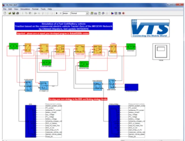
Figure 5 Downloadable Matlab SimulinkTM simulation program vehicle speed (m/s) time (s) (a) (b) (c) (d) vehicle speed (m/s) vehicle speed (m/s) vehicle speed (m/s)
Figure 6 Considered driving cycles: (a) Adapted NEDC, (b)
WLTC, (c) urban driving cycle and (d) scoring driving cycle
In order to develop and to test their strategies, a unique simulation program capable of simulating different strategies with the same local control was developed and provided to the participants. This was built under the Matlab SimulinkTM software (figure 5). Then, the EMR and the control scheme of the vehicle have been implemented in Matlab SimulinkTM using an EMR SimulinkTM library with basic elements. This program is totally open and still downloadable [14]. It can be used according to a user interface in order to build an expertise and facilitate the EMS developments (choice of the simulated driving cycle (figure 6a,b,c), end of simulation graphs and report, etc.). A dedicated website [14], a technical email, a forum assistance and the related VPPC 2016 paper [10] have helped the participants in their achievements. The strategy scoring was carried out on a driving cycle unknown to the participants (figure 6d). This 32.6 km driving cycle include urban and extra urban parts and was obtained from a real
Tazzari Zero driving test. Finally, an optimal Dynamic Programming (DP) strategy has been developed for the scoring step. This has been carried with the knowledge of the driving cycle to determine if the participant’s strategies are close to the theoretical global optimal cost.
Participation
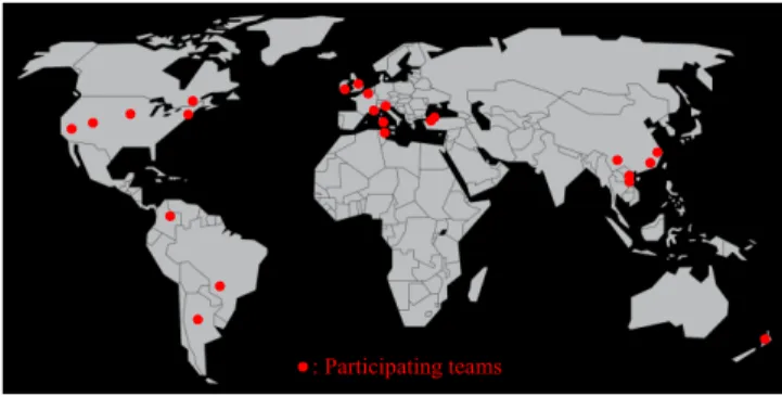
In total, 48 academic (54 %), student (40 %) and professional (6 %) participants from 14 different countries took part in the challenge (figure 7). The teams that developed the best EMSs received an award that consisted of: a certificate, an invitation to write and present a paper for the IEEE-VPPC’17, and a grant that covered all expenses related to the participation and attendance to IEEE-VPPC’17 (conference registration, transport, hotel, etc.).
First prize: up to a limit of 3000 US$; Second prize: up to a limit of 1500 US$.
From a participation survey, all the participants were interested by the open-ended program (available models, Matlab SimulinkTM program, etc.). 80 % was also motivated by the competitive nature of the proposed challenge. Participate to an international challenge to compare their work on a common subject and criteria then appears as a motivation for many researchers.
: Participating teams
Figure 7 World map participation (world map from commons.wikimedia.org)
Results and discussion
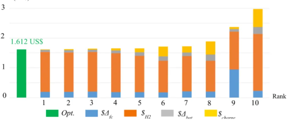
The ten best participant strategy costs are compared in figure 10. The FC degradation $Δfc, the battery degradation $Δbat, the H2 consumption $H2 and the final battery charge cost $charge are differentiate from the global cost $global. Some participant strategies are close to the theoretical DP optimum of 1.612 US$ (green chart). The best EMS allows to perform the scoring driving cycle of figure 6d with a global cost of 1.624 US$ (+ 0.73%) compared to 1.629 US$ (+ 1.05%) for the second. The cost differences at the leader group are very low because the cost distribution is quite similar than for the DP optimal strategy (figure 8 and figure 10). Here, the H2
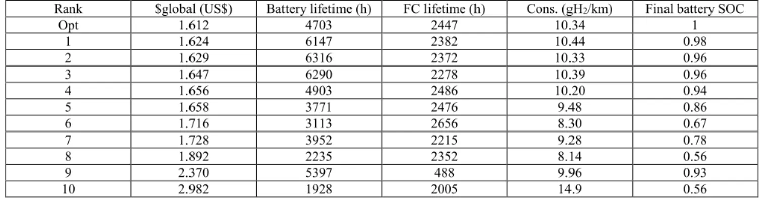
consumption represents 82 % of the trip cost. However, even if the fuel consumption during a trip is an important part of the global cost, it is not the major key issue of a competitive EMS (table 2). Indeed, low consumptions during a trip are not related to the best strategies. For example, the best strategy allows to consume 10.34 gH2/km during the scoring trip compared to only 8.14 gH2/km for the 8th strategy. However, this consumption does not consider the additional related battery charging H2 consumption. The final battery charging cost $charge appears as a major key issue in the EMS development (yellow part in figure 10 and table 2). In a general way, lower is the final battery SoC, higher is the global cost because maintain a low SoC 1) degrades the battery during the trip and 2) requires to charge the battery with a high current of 248 A at the end of the trip, which corresponds to the best FC efficiency point. This is related to additional battery and FC degradations (figure 9). This means that keeping a high battery SoC during the driving cycle will ensure a low charge cost at the end, and then a low global cost. This also reduces the battery degradation (table 2). The 9th strategy respects this criterion. However, its global cost is high (2.37 US$) because of several FC start/stop events. This increases the FC degradation and reduces its lifetime to 488 h. In this way, considering a repetitive sequence of the scoring cycle, the FC can operate 2,656 h with a well-designed EMS. This must be balanced with the battery lifetime to perform a competitive EMS (table 2).
$charge $Δfc $H2 $Δbat
82% 6% 12%
Figure 8 Optimal cost distribution
0 0 Cost (US$) Battery SOC at the end of the cycle $Δfc $H2 $Δbat 0.2 0.4 0.6 0.8 1 1.2 1.4 100 90 80 70 60 50 40 30 20 10
All the EMSs are based on heuristic strategies to reduce the H2 consumption and the source degradations. Based on the challenge specification and on their expertise, the participants designed their strategies from various inputs and heuristic rules [15]-[19]. The best strategy maintains the battery SoC at it maximal value while the FC operates at its maximal efficiency and lower degradation operating [15]. [16] and [17] (4th and 5th positions) use similar concepts to build their EMSs but they do not reach such good results because they neglect the battery SoC effect on the battery degradation. The second best strategy extracts comprehensive rules from optimized results of twelve typical driving cycles [18]. The third best EMS defines the most suitable FC reference current depending on the battery SoC and the traction power by means of a look-up table [19]. The challenge participants then had to find an acceptable compromise between the H2 consumption and the source's degradations without any information about the future scoring driving cycle. This is the most interesting issue that the challenge participants faced during the competition. Look-up tables, relays, fuzzy logic functions or genetic algorithm are then combined to design the EMS depending on the battery SoC, the FC voltage, FC current, the traction reference force, etc. In this way, even if the developed strategies are different and sometimes complex, it did not take much time for competitors to achieve competitive results. From a participation survey and considering the challenge deadlines, participants have, on average, spent between 10 to 30 days to develop their strategies. This time period is relatively short, considering that participants had to assimilate a simulation program and the organization formalisms (i.e. EMR).
It is possible to conclude that, with a good expertise and a good knowledge of the system, one comes to efficient on-line managements and this, rather quickly. For example, based on the proposed models, it appears that maintaining a high battery SoC is an important key issue to reduce the global trip cost. On
the other hand, the influence of management remains predominant and a bad analysis of the system can quickly result in high cost (e. g. EMS from the 9th participant).
Conclusion
An international challenge devoted to the energy management of a fuel cell/battery vehicle was launched in October 2016 during the IEEE-VPPC’16, in Hangzhou, China. In total, 48 participants from 14 different countries took part in this challenge. It has rewarded the best EMSs based on a common vehicle and specifications. The vehicle driving cost, which includes the hydrogen and the source degradation costs, was used as a base of comparison. For example, the best strategy passed through the scoring driving cycle for an overall cost of 1.62 US$ against 2.98 US$ for the tenth (+ 84 %). In this way, well designed EMS may lead to reduce significantly the trip cost while ill-designed EMS may lead to high fuel consumption or premature source degradations.
Tight deadlines have deliberately limited the development times, but the best results are close to the theoretical dynamic programming optimum. Thus, although the developed strategies are different and sometimes complex, it did not take much time for participants to achieve competitive results. Knowing in advance the mission profile also does not appears so important because the best developed strategies have quite similar results than for the DP optimal strategy.
The top scoring participants have been distinguished and presented their results in a special session at the IEEE-VPPC’17 in Belfort, France. 7 papers were presented. This special session was also an opportunity to present the second IEEE VTS Motor Vehicles Challenge 2018 focused on the energy management of a Range Extender Electric Vehicle, the Chevrolet Volt [20].
Rank $global (US$) Battery lifetime (h) FC lifetime (h) Cons. (gH2/km) Final battery SOC
Opt 1.612 4703 2447 10.34 1 1 1.624 6147 2382 10.44 0.98 2 1.629 6316 2372 10.33 0.96 3 1.647 6290 2278 10.39 0.96 4 1.656 4903 2486 10.20 0.94 5 1.658 3771 2476 9.48 0.86 6 1.716 3113 2656 8.30 0.67 7 1.728 3952 2215 9.28 0.78 8 1.892 2235 2352 8.14 0.56 9 2.370 5397 488 9.96 0.93 10 2.982 1928 2005 14.9 0.56
1 2 3 4 5 6 7 8 9 10 0 1 2 3 Cost (US$) Rank 1.612 US$ $charge $Δfc $H2 $Δbat Opt.
Figure 10 Best scoring driving costs
References
[1] M. Sorrentino, G. Rizzo, and L. Sorrentino, "A study aimed at assessing the potential impact of vehicle electrification on grid infrastructure and road-traffic green house emissions", Applied
Energy, vol. 120, pp. 31-40, May 2014.
[2] G. Pasaoglu, A. Zubaryeva, D. Fiorello, and C. Thiel, “Analysis of the European mobility surveys and their potential to support studies on the impact of electric vehicles on energy infrastruscture needs in Europe”, Technological Forecasting &
Social Change, vol. 87, pp. 41-50, Sep. 2014.
[3] D. J. Durbin, and C. Malardier-Jugroot, “Review of hydrogen storage techniques for on board vehicle applications”, Int.
Journal of Hyd. En., vol. 38, no. 34, pp. 14595-14617, Nov.
2013.
[4] B. Chen, Y. Cai, Z. Tu, S. Hwa Chan, J. Wang, and Y. Yu, “Gas purging effect on the degradation characteristic of a proton exchange membrane fuel cell with dead-ended mode operation I. With different electrolytes”, Energy, vol. 141, pp. 40-49, Dec. 2017.
[5] C. Dépature, W. Lhomme, P. Sicard, A. Bouscayrol, and L. Boulon, “Real-Time Backstepping Control for Fuel Cell Vehicle Using Supercapacitors”, IEEE Trans. Veh. Technol., vol. 67, no. 1, pp. 306-314, Jul. 2017.
[6] T. Yoshida, and K. Kojima, “Toyota MIRAI fuel cell vehicle and progress toward a future hydrogen society”, The Electrochemical
Society Interface, vol. 24, no. 2, pp. 45‑ 49, Sum. 2015.
[7] R. Álvarez-Fernández, F. Beltrán Cilleruelo, and I. Villar Martinez, “A new approach to battery powered electric vehicles: A hydrogen fuel-cell range extender system”, International
Journal of Hydrogen Energy, vol. 41, no. 8, pp. 4808-4819, Mar.
2016.
[8] N. Sulaiman, M. A. Hannan, A. Mohamed, E. H. Majlan, and W. R. Wan Daud, “A review on energy management system for fuel cell hybrid electric vehicle: Issues and challenges”, Renewable
and Sustainable Energy Reviews, vol. 52, pp. 802‑ 814, Dec.
2015.
[9] F.R. Salmasi, “Control Strategies for Hybrid Electric Vehicles: Evolution, Classification, Comparison, and Future Trends,” IEEE
Trans. Veh. Technol., vol. 56, no. 5, pp. 2393–2404, 2007.
[10] C. Dépature, S. Jemei, L. Boulon, A. Bouscayrol, N. Marx, S. Morando, and A. Castaings, “IEEE VTS motor vehicles challenge 2017 – Energy management of a fuel cell/battery vehicle”, IEEE
VPPC16, Hangzhou, China, Oct. 2016.
[11] http://www.tazzari-zero.com/ - “Tazzari Zero Website”, Jul. 2017.
[12] A. Bouscayrol, B. Davat, B. de Fornel, B. François, J. P. Hautier, F. Meibody-Tabar, E. Monmasson, M. Pietrzak-David, H. Razik, E. Semail, and M.F. Benkhoris, “Control Structures for Multi-machine Multi-converter Systems with upstream coupling,”
Math. Compu. Simul., vol. 63, no. 3-5, pp. 261-270, Nov. 2003.
[13] A. Bouscayrol, J. P. Hautier, and B. Lemaire Semail, “Systemic design methodologies for electrical energy systems Analysis, Synthesis and Management”, Chapter 3: Graphic formalism for the control of multi-physical energetic system: CoG and EMR,
ISTE and Wiley, ISBN 978-1-84821-3888-3, 2012.
[14] http://www.uqtr.ca/VTSMotorVehiclesChallenge17
[15] E. G. Amaya, H. Chiacchiarini, C. De Angelo, and M. Asensio, “The Energy Management Strategy of FC/Battery Vehicles Winner of the 2017 IEEE VTS Motor Vehicles Challenge”, IEEE
VPPC17, Belfort, France, Dec. 2017.
[16] K. Davis, and J. G. Hayes, “Energy Management Strategy Development to Minimize the Operating Costs for a Fuel Cell Vehicle”, IEEE VPPC17, Belfort, France, Dec. 2017.
[17] F. Duchossois, N. Madi, and J. Pascal, “Ruled-based energy management strategy for a Fuel- Cell battery vehicle”, IEEE
VPPC17, Belfort, France, Dec. 2017.
[18] Z. Chen, N. Guo, Q. Zhang, J. Shen, and R. Xiao, “An Optimized Rule Based Energy Management Strategy for a Fuel Cell/Battery Vehicle”, IEEE VPPC17, Belfort, France, Dec. 2017.
[19] A. Serpi, and M. Porru, “A Real-Time Energy Management System for Operating Cost Minimization of Fuel Cell/Battery Electric Vehicles”, IEEE VPPC17, Belfort, France, Dec. 2017. [20] C. Dépature, S. Pagerit, L. Boulon, S. Jemeï, A. Rousseau, and A.
Bouscayrol, “IEEE VTS Motor Vehicles Challenge 2018 – Energy Management of a Range Extender Electric Vehicle”,
IEEE VPPC17, Belfort, France, Dec. 2017.
Author information
Clément Dépature received his master’s degree in
Electrical Engineering from University Lille1 (France) in 2011. In 2011, he has been engaged as an engineer at L2EP, in Lille. He was in charge of the development of an experimental platform dedicated to electric and hybrid vehicles.
In 2017, he obtained a Ph.D in collaboration with University Lille1 and Université du Québec à Trois-Rivières (Canada). Since 2017, he has a postdoctoral position at the Hydrogen Research Institute. His research activities deal with modeling, linear and non-linear control and energy management for fuel cell, hybrid and electric vehicles.
Samir Jemeï received the M.S. degrees in electrical
engineering from University of Franche-Comté, France, in 2001 and the Ph.D. degree in engineering sciences from University of Franche-Comté, France, in 2004.
From 2005 to 2010, he was a Research Engineer with the Energy Department of FEMTO-ST Institute. Since 2010, he has been an Associate Professor with the University of Franche-Comté. He received his habilitation to conduct researches in 2016. Their research activities deal with Diagnosis and Prognosis of Fuel Cell Systems and also with Energy Management of Hybrid systems. Since 2011, he is also chairman of the scientific axis “Fuel Cell Systems and Ancillaries” at FuelCell Lab (FR CNRS 3539) and FEMTO-ST Institute (UMR CNRS 6174) in Belfort, France.
Loïc Boulon received the master degree in electrical and
automatic control engineering from University Lille1, in 2006. Then, he obtained a PhD in electrical engineering from University of Franche-Comté (France). Since 2010, he is a professor at Université du Québec à Trois-Rivières and he works at the Hydrogen Research Institute (Full Professor since 2016). His work deals with modeling, control and energy management of multiphysics systems. His research interests include hybrid electric vehicles, energy and power sources (especially battery in cold weather operation), and fuel cell systems.
In 2015, Loïc Boulon was general chair of the IEEE-Vehicular Power and Propulsion Conference in Montréal (QC, Canada). Prof. Loïc Boulon is VP-Motor Vehicles of the IEEE Vehicular Technology Society and he is the holder of the Canada Research Chair in Energy Sources for the Vehicles of the future.
Alain Bouscayrol received a Ph.D. degree in Electrical
Engineering from the Institut National Polytechnique de Toulouse, France, in 1995.
From 1996 to 2005, he was Associate Professor at University Lille1, where he has been a Professor since 2005. Since 2004,
he has managed the national network on Energy Management of Hybrid Electric Vehicles France. He has initiated the Energetic Macroscopic Representation (EMR) in 2000 for the description and the control of energetic systems. His research interests at the L2EP include graphical descriptions for control of electric drives, wind energy conversion systems, railway traction systems, hybrid electric vehicles and hardware-in-the-loop simulation.
Neigel Marx received his phD degree in Electrical
Engineering from University of Franche-Comté, in 2017. His research area cover modeling and energy management of fuel cells and multi fuel cell systems.
Simon Morando obtained his master degree in 2012 in
Electrical Engineering from the university of Franche-Comté. Then, he joined the FEMTO-ST institute as a Ph.D student, and works in collaboration with the Energy and Automatic department (AS2M). In 2015, he received a PhD in electrical engineering from University of Franche-Comté. Since this date, he has a postdoctoral position at FCLAB institute. His research area cover characterization, diagnosis and prognosis of Fuel cell, specially using Artificial Intelligence methods.
Ali Castaings received his engineer degree and his master’s
degree in Electrical Engineering from Arts et Métiers ParisTech (France) in 2012. He received his PhD degree in Electrical Engineering from University Lille1 in 2016. He is an active member of the French research network on hybrid and electric vehicles, MEGEVH and has been involved in several projects on energy management of hybrid and electric vehicles. His research activities deal with energy management of multi-sources vehicles, including battery, supercapacitors, and fuel cells.