A Comprehensive Review of Solutions and
Strategies for Cold Start of Automotive
Proton Exchange Membrane Fuel Cells
ALI AKREM AMAMOU1,2, SOUSSO KELOUWANI1, LOIC BOULON1,2, AND KODJO AGBOSSOU1,2
1Institut de Recherche sur l’Hydrogène, Université du Québec à Trois-Rivières, Trois-Rivières, QC G9A 5H7, Canada 2Groupe de Recherche en Électronique Industrielle, Université du Québec à Trois-Rivières, Trois-Rivières, QC G9A 5H7, Canada Corresponding author: A. Amamou (ali.amamou@uqtr.ca)
This work was supported in part by the Bureau de l’éfficacité et de l’innovation énergétique, Ministère des Ressources Naturelles et de la Faune du Québec and in part by the Natural Science and Engineering Research Council of Canada.
ABSTRACT Proton exchange membrane fuel cell (PEMFC) can be a significant eco-friendly alternative power source for vehicles. However, under subfreezing conditions, cell degradation and irreversible perfor-mance decay can occur because of ice formation and repetitive thaw/freeze cycles. These problems have limited the further commercialization of PEMFC in cold weather countries. Thus, many improvements have been made to repair the freeze protection and rapid cold startup problems in PEMFC vehicles. In this paper, a comprehensive review dedicated to engineers of the recent research progress on the PEMFC cold start problems is presented. Systems and methods for fuel cell shutdown are summarized and classified into two categories: purge solution and material to avoid freezing. Regarding the system and solutions for PEMFC cold startup, different heating solutions are classified into two main groups depending on their heating sources and categorized as internal and external heating methods. This paper concludes with a detailed review of cold startup strategies based on an exhaustive survey of journal papers and patents.
INDEX TERMS Cold start strategies, heating solutions, hybrid and electric vehicles, PEMFC, purge.
I. INTRODUCTION
Energy demand is growing dramatically, a very critical prob-lem due to the related pollution, the depletion of fossil resources and the high cost [1]. More and more studies are focusing on finding alternative renewable energies. Hydrogen is, therefore, one of the most important substitutes for gas, and fuel cells are considered a promising solution [2].
A fuel cell is a device that converts hydrogen into electric-ity through an electrochemical reaction. The proton exchange membrane fuel cell (PEMFC) is a type of fuel cell developed essentially for transportation and residential power genera-tion [3], [4]. The PEMFC operagenera-tion is based on an electro-catalytic reaction with the hydrogen oxidation at the anode and the oxygen reduction at the cathode [2]. A PEMFC has the advantages of high efficiency, high power density, quick response, low/zero local emission levels and low operating temperature (50-100 ◦C) [5]. Various phenomena occur-ring duoccur-ring fuel cell operation, including electrochemical reactions, electronic /ionic transport, and heat/mass trans-fer, govern the operation of the fuel cell. PEMFCs have passed the test or demonstration phase and have reached the
commercialization stage due to an impressive worldwide research effort. However, further scientific improvements are needed to overcome barriers related to durability, cost and cold startup to enable fuel cell commercialization.
Breakthroughs in material development, performance
improvement, and development of new strategies, analytical models and experimental tools are particularly important for the current fuel cell evolution [6]. The cold startup is of critical importance for optimal PEMFC performance and durability. The water produced at the cathode through the electrochemical reaction could freeze and lead to ice formation under subfreezing temperatures [5]. The ice that is formed can reduce the performance, damage the cell components, block the gas passage, coat the catalyst and lead to cold start failure [7].
A detailed understanding of the cold start mechanisms and developing related operative solutions are the main interest of many studies [8]. Different works focusing on cold startup of the fuel cell aim to satisfy the specific targets for cold start performance set by several countries and regions. For example, in the United States, the latest target was set by
the Department of Energy (DOE) in 2012, which in 2020, requires a rapid startup of a fuel cell vehicle to 50 % rated power soaked at −20 ◦C in less than 30 s with less than 5 MJ of energy. The DOE also requires unassisted successful start up from −30 ◦C [9]. There are worldwide technical targets for the next few years. The European Union aims to achieve the lowest cold start at −25◦C and to maintain a good proton conductivity at low temperatures (over 10 mS cm−1 at −20 ◦C) [10]. General Motors Corporation also has a target of achieving unassisted startup from −40◦C [10]. The plan of the Japanese government has shifted from ‘‘strategic development’’ to ‘‘commercialization promotion’’ [10]. For example, Toyota commercialized one of the first hydrogen fuel cell vehicles (the Toyota MIRAI) in 2015, and one of the large technical issues addressed by Toyota over several years is the cold start from −30◦C. Toyota announced that it
had become possible to start up the FCHV at temperatures
down to −30 ◦C and has announced royalty-free use of
approximately 5680 fuel cell related patents until the end of 2020, including critical technologies developed for the new Toyota MIRAI.
The recent literature contains several review papers on cold startup PEMFC. Wan et al. [11] published an extensive review on the cold start of PEMFCs, but its main focus was on the state and phase changes of water in the PEMFCs, the impacts of water freezing on PEMFCs and model-ing and experimental work on the cold start of PEMFCs. Meng and Ruan [12] also presented a comprehensive review of the experimental and numerical research on PEMFC cold start phenomena. Pesaran et al. [13] published an important report concerning PEMFC freeze and rapid startup inves-tigation as part of NREL’s 2005 Hydrogen, Fuel Cell and Infrastructure Technologies (HFCIT) Annual Operating Plan with the U.S. Department of Energy (DOE). This report categorized more than 100 patents related to PEMFC cold startup and investigated the problem of rapid startup from subfreezing temperatures and solutions that could address them.
All of these reviews have presented the experimental and numerical research on cold start of PEMFC and focused on identifying the main parameters that influence the cold start performance, but no comprehensive review has classified and compared the different heating solutions, purge solution and cold startup strategies. Over the last few years, in an effort to enhance the cold startup of PEMFC systems for automobile applications, significant progress has been made in the development of a purge solution, the generation of alternate materials less susceptible to freeze damage and the improvement of heat generation and management systems. In addition, various strategies for cold start problems have been developed and reported through a considerable number of papers and patents. Consequently, there is a need for a detailed review regrouping and comparing the different heat-ing solutions (internal and external), the several solutions for shutdown processes (purge, material to avoid freezing) and the main cold startup strategies.
The purpose of this review is therefore to summarize the studies conducted by academic and industrial researchers on the cold startup of PEMFC, but the review does not include modeling work because a discussion of modeling work was recently presented by Wan et al. [11]. First, a description of cold start problems of PEMFC is provided for a clear under-standing of what happens to fuel cells during these processes. Second, systems and methods for fuel cell shutdown are summarized and investigated. Third, systems and methods for fuel cell startup are discussed in detail. The paper concludes with a detailed review of cold startup strategies, based on an exhaustive survey of journal papers and patents.
II. ENGINEERING PERSPECTIVES OF COLD START PROBLEMS OF PEMFCs
The residual water in the PEMFC at subzero temperatures prevents cold startup and causes irreversible degradation of the PEMFC [14], [15]. When the fuel cell is subjected to sub-freezing temperatures for a long time, the residual water in the stack can freeze, leading to irreversible performance decay and hence to mechanical damage of the cell components, even causing physical breakdown [16]. The repeated freeze/thaw cycles will cause damage to the structure and performance of the cell components [16], [17].
Many researchers have studied the freezing mechanism and cold start performance and found that subfreezing temperatures cause a reduction in the oxidation cath-ode reduction (OCR) value and the fuel cell maximum power (approximately 2.4% of the maximum power loss is observed after 3000 cycles) [18]. The gas diffusion layer (GDL), the catalyst layer (CL) and the electrolyte mem-brane were also shown to suffer the most damage [14], [19]. Therefore, the electrolyte membrane is one of the most impor-tant elements in PEMFCs because this membrane directly affects the fuel cell performance. When water freezes inside the membrane, it damages the membrane electrode assem-bly (MEA). The water volume inside the cell expands by 9% due to the difference between water and ice densi-ties (0.9998 and 0.9168 g·m−3, respectively) [20]. Moreover, the repetitive cycles of freezing and melting of water on the surface of the membrane delaminate the catalyst layers of the membrane and of the gas diffusion layer [20], [21]. Cracks in the membrane cause gas crossover and, in turn, lead to an uncontrolled reaction between oxygen and hydrogen with subsequent pinhole formation, reducing the life of the cell and ruining the membrane [21].
The research reported in [22] and [23] associated the ice formation on the membrane surface with its initial water content and thickness. The authors concluded that the higher the initial water content is and the thicker the membrane is, the thicker the developing ice layer will be. Further-more, Schmittinger and Vahidi [16] and Park et al. [24] carried out many tests showing that the cracking of fully hydrated membranes and performance decrease (approx-imately 0.4 mV/cycle of degradation at 1 A/cm2) was observed after several freeze/thaw cycles (from −30◦C to
20 ◦C/70 ◦C). Therefore, the lower the hydration state of
the membrane is after shutdown, the less serious the cracks will be [16]. Mukundan et al. [25] observed that the lower the water content is, the higher the conductivity of a Nafion membrane is for temperatures below 0◦C. Tajiri et al. [26] tested isothermal cold startup at −31 ◦C, and they showed that the membrane is a critical component for improving the cell performance during isothermal startup.
To investigate the impacts of ice on the GDL and CL, many researchers [27]–[30] have studied freezing that depends on temperature and on the GDL. The results indicate that the water content during operation and after shutdown was frozen at the interface of CL and GDL at −10◦C and in the CL at −20◦C [30]. Moreover, Fuller and Wheeler [31] showed that most of the residual water was in the GDL and the gas chan-nel, not on the CL. Oszcipok et al. [32] and Hou et al. [33] drew the conclusion through statistical analyses of the exper-imental results that residual water at −5◦C froze in the GDL instead of reaching the flow field and hindered the transport of the reactant gases but did not affect the electrochemical active surface area. Ice formation mainly affects the cathode layer pores and could hinder the O2transport, which increases
the electrical resistance of the cell [29], [34]. Therefore, the fuel cell reaction is limited or even inhibited due to severe voltage drops [14]. Additionally, bipolar and flow channels are blocked by ice, which causes startup failure and electrode deterioration due to localized fuel starvation [11]. Consequently, it is very important to prevent water freezing in the flow channels, and research on this topic should be performed. Hou et al. [35] studied the effect of repeated cold start failure and showed that significant performance degradation was detected due to the change of the reactive region from the membrane/CL region to the CL/GDL region as blockages developed.
All research reported in [36]–[38] presents a summary of critical parameters for the cold startup of fuel cells, and some conclusions are summarized in Table 1. In this context, many studies showed that purging residual liquid water at shutdown is the key to a successful cold start. Other studies focused on finding heating solutions at startup to raise the stack temperature above the freezing point of water and prevent ice blockage from occurring. On the one hand, the differ-ent studies aim to obtain a successful cold start and avoid performance degradation. On the other hand, they attempt to satisfy the specific targets for cold startup time and energy requirement.
III. SYSTEMS AND SOLUTIONS FOR FUEL CELL SHUTDOWN
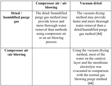
In this section, the different systems and solutions for fuel cell shutdown will be investigated. The present systems and methods aim to avoid water freezing during shutdown and particularly, to improve the ability of a fuel cell to start following exposure to freezing conditions. First, the different purge solutions will be presented and are divided into three main methods: ‘‘Dried or humidified purge gas’’, ‘‘Purge with
TABLE 1.Summary of model results and critical parameters for the cold start [36].
compressor air or air blowing’’ and ‘‘Vacuum dried purge’’. Second, solutions to avoid freezing at shutdown by using alternate materials less susceptible to freeze damage will be presented.
A. PURGE SOLUTION
Based on reviews of the cold start PEMFC literature, it is clear that purging residual water that remains in the fuel cell system at shutdown is the key to a successful cold start. This purging is performed to reduce ice formation that can cause system damage within the stack and to improve the ability to restart the fuel cell from freezing temperatures [39]. For a successful cold start, the amount of the liquid water must be minimized at system shutdown [40]. All of the purge solutions are effective to minimize the majority of the liquid water, but they do not have the same effectiveness in removing the residual water after the purge. The residual water will freeze at subzero
temperatures, which hinders the smooth supply of reactant gas [13], [41].
Several researchers have suggested effective purge meth-ods. The research reported in [42]–[44] proposed to purge the anode side and/or cathode side reactant gas flow channels using compressor air or an air blowing process. The standard purge method of air blowing is not consistently effective because the difference in the water concentration between the CL and the channel is too small to transport water to the channel in a limited time [18].
Using the method proposed in [41], [42], and [45]–[50], water is purged from the passages by flowing a dried or humidified reactant stream through at least a portion of the fuel cell stack prior to shutting down the power gen-erating system. The dried reactant may be, for example, an inert liquid or gas (such as nitrogen) or one of the tant streams [46]. Referring to this method, a dried reac-tant generates a large amount of heat, which significantly increases the amount of residual water evaporation in the GDL and CL [18]. The water carrying capacity of a gas is increased by decreasing the gas pressure [46]. In other embodiments, drying may be accomplished by operation of the fuel cell in such a way as to create a drying condition that causes a net outflux of water from the stack [51], [52]. Tajiri et al. [49] presented a novel experimental procedure to achieve excellent water removal performance of a dry purge gas using the high frequency resistance (HFR) of the cell as an indicator of membrane water content and hence of purge effectiveness. Tajiri et al. [49] compared purge gas flow rate and relative humidity of two purge gases, helium (He) and nitrogen (N2), at different temperatures and found that
a helium gas purge has better performance due to its higher water diffusivity, particularly for shorter purge durations and lower purge temperatures. In another study, Tajiri et al. [50] developed an equilibrium purge solution in which the fuel cell is purged with partially humidified gas for a long period of time (typically 3 h or more) to remove all of the liquid water in the PEMFC and to equilibrate the ionomer in the CL and the PEM with the purge gas relative humidity. Whereas the equilibrium purge is useful to evacuate most of the water on the CL and the membrane electrolyte, a practical gas purge for FCVs requires a much shorter duration, preferably less than 60 s, and high efficiency [49]. Tajiri et al. [50] performed a comparison between cold start after equilibrium purge solu-tion using partially humidified purge gas and after the dry gas purge solution. They concluded that the equilibrium purge cold start has 0.5 and 0.3 mg cm−2larger amounts of product water than the dry purge cold start for −20 and −30 ◦C, respectively [50].
All studies reported in [44], [53], and [54] recommend evaporating water out of the fuel cell using a sudden pres-sure reduction, called vacuum drying, before storing the fuel cell under freezing conditions. The vacuum drying is the removal of liquid from a component at reduced air pres-sure so that it dries at a lower temperature than would be required at full pressure [44]. However, this method has
limited use in the fuel cells composed of porous water trans-port plates because, in this case, there is a too much water to be purged by slow evaporation into the vacuum stream [54]. The intensity of the applied vacuum depends on the fuel cell temperature. A lower vacuum can be applied at higher temperatures than at lower temperatures to affect the same amount of dehydration. Preferably, evacuation will occur just after the deactivation of the fuel cell while it is still warm [54]. Tang et al. [44] compared the latter method to purging using dry N2, and experimental results have demonstrated
that the vacuum drying method may provide faster and more thorough water removal than N2purging. Table 2 summarizes
a comparison between the different purge solutions presented above.
TABLE 2.Comparison between different purge solutions.
For automotive applications, purge duration is very impor-tant because additional energy is consumed during the purge process, and it must be controlled to avoid total membrane dehydration [13], [41], [42]. Moreover, the flow rate of purge gas, time of purge start and fuel cell temperature are important factors for a successful purge. Therefore, an effective purge strategy is necessary [18]. Two purge strategies were investi-gated by St-Pierre et al. [45]. When the first strategy, namely, dry gas purge, is used immediately after the shutdown of the fuel cell, the cell performance decreases continuously at high current densities, but no significant decrease in the cell performance was observed when the second strategy, namely, dry gas purge after the fuel cell cooled down, was used. Several researchers [45], [46] have found that purging only the cathode yields satisfactory results and contributes to fuel efficiency. Some researchers [45], [55]–[57] observed ice formation on the stack during purging time by employ-ing silver screen GDLs or microholes. Water was shown to evaporate first in the channels, followed by the gas diffusion layers and finally the membrane when dry gas flows through the fuel cell. As a result, the stack resistance, due mostly to the membrane resistance, increases slightly due to the water evaporation in channels and GDL and more rapidly as
water is evacuated from membrane. The membrane resistance increases critically if the purge is too long, which limits the current drawn during cold startup and thus the amount of heat generated. In the same study, experimental results showed that the ideal purge duration is in the range of 90-120 s, which will reduce the water content to the needed level before a cold startup [55]–[57]. In another study, the purge duration was generally limited to 2 min in fuel cell vehicles [58], [59]. Roberts et al. [46] focused on the effect of stack temperature on purge performance and found that the fuel cell temperature must be greater than the freezing temperature of water and preferably at least approximately 20 ◦C below the normal stack operating temperature, more preferably in the range of approximately 15◦C to 30◦C. Sinha and Wang [60] modeled the specific effects of the gas purge to better understand the water removal processes during the gas purge. The model considers water transport in the GDL and predicts the energy requirements as well as the drying times of the GDL. The model can successfully predict that an efficient water removal is favored by a low gas relative humidity, high gas flow rates and high cell temperature.
B. MATERIAL TO AVOID FREEZING
The patent literature is richer and includes solutions to avoid freezing at shutdown by using alternate materials less sus-ceptible to freeze damage (for example, coolants that do not freeze at subfreezing temperatures). Some researchers proposed a PEMFC cooling system with a low freezing temperature, non-electrically conductive heat transfer fluid to replace pure water as a coolant [61]. A pure glycol and deionized water coolant mixture may be used as a coolant to obtain suitable antifreeze protection [62], [63]. Usually, the additive package contains an organic corrosion inhibitor and a polymeric ion suppressant to avoid the cor-rosion process on the bipolar plates [62]. There are other coolant compositions such as mixtures of 1,3-propanediol or mixtures of 1,3-propanediol with alkene glycols and/or derivatives [64]. To improve the PEMFC performance at subfreezing temperature, it is recommended to separate stack and radiator coolant loops that are thermally coupled with a heat exchanger [61].
To avoid the freezing problem, Converse and Mueller [65] used a heat exchanger arranged in a fluid communica-tion component. The heat exchanger has a cooling rate greater than the component cooling rate. With this solution, water vapor will condense and freeze in the heat exchanger rather than in the component, avoiding malfunction of the fuel cell component during freezing temperatures [65]. Ko et al. [66], [67] proposed a dual-function microporous layer (MPL) to provide additional volume for ice storage during cold start operations, which improves the cold start capability of PEMFC. A freeze-tolerant fuel cell system that is based on separating the coolant loop from the membrane through the use of gaskets interposed between the collector cell plates was developed by Barbir et al. [68]. The freeze tol-erant system also requires flowing a coolant fluid other than
pure water having a sufficiently low freezing point through the coolant loop [68].
IV. SYSTEM AND SOLUTIONS FOR FUEL CELL STARTUP
In this section, the different rapid heating solutions will be investigated. Rapid heatup can raise the stack temperature above the freezing point of water and prevent ice blockage from occurring [13]. Many studies suggested different heat-ing solutions that can be divided into two main methods: ‘‘external heating’’ that uses heat generated from an external heating source and delivers it into the stack through a heat transfer medium and ‘‘internal heating’’ that uses heat gener-ated within the stack [13].
A. EXTERNAL HEATING
The external heating solutions are grouped into three cat-egories according to the heat source used. The first group uses a heater to heat up the stack, the second group uses battery energy, and the third category uses a catalytic burner to increase the stack temperature.
In the first category, several researchers [69]–[73] used a heater for instantaneously heating water in the fuel cell system upon startup. In subfreezing temperatures, a ther-mal management system is adapted to deliver a liquid heat exchange fluid or the coolant water, which passes through the channels in the cell and as a result, raises the cell temperature. Wheat et al. [74] also employed a startup heater coupled to a blower that provides air to warm the fuel cell stack and the water supply. The heater can be powered by the fuel cell or the battery. In other studies, hot air could be obtained by adiabatic compression at an air supply portion of the cell, and the hot air is divisionally supplied into a warmup box through a warmup valve [75].
Within the second category, some patents use additional current delivered by a battery that can be connected to the fuel to force the weak cells in the stack to a negative cell voltage. Heat is thus produced as a consequence of polarization within the cell. As the weak cells heat up, they quickly approach the typical performance of the good cells [76], [77]. In another study [78], the cold start procedure is accomplished through heating the fuel cell by applying a voltage of approximately 2.4 V between the electrodes to perform electrolysis of water in the fuel cell. The over-potential excluding the part used for electrolysis, which is approximately 1.2 V, is converted to heat and can be used for melting ice [78]. The method, according to Korytnikov and Novak [79], consists of connect-ing the fuel cell to a battery into an external electric circuit and maintaining a fuel cell voltage between the cathode and the anode at a value of below approximately −0.4 V to prevent the electrolysis of water and an attendant generation of oxygen at the anode. The hydrogen ions pass from the anode through the proton exchange membrane to the cathode, and the electrons are conducted through the external electrical circuit to the cathode to drive the exothermic reaction.
As another external heating method, a pressurized fuel such as hydrogen is used to produce a catalytic oxidation
reaction at a catalytic burner, which will produce heated gas that will exchange heat with the fuel cell compo-nents [80]–[82]. Johnson and Kanouff [83] developed a high-efficiency, compact catalytic burner that uses the catalytic oxidation of hydrogen to provide heat to a hydrogen stor-age system. As one can see from above, there are different external heating solutions to warm up the stack, but each method has its drawbacks. Table 3 shows the advantages and drawbacks for different external heating solutions.
TABLE 3. Advantages and drawbacks of different external heating solutions.
B. INTERNAL HEATING
The heating methods relying on external heating sources can be effective in subfreezing conditions and fulfill the cold start targets. However, the addition of other heating devices increases the volume, weight, and cost of the fuel cell sys-tem and also lowers the energy efficiency, which is a draw-back [84], [85]. Therefore, several researchers developed a self-startup solution of PEMFC from subzero temperatures by using heat generated within the stack.
Before listing the different internal heating solutions, it is important to recall the internal behavior of PEMFC at low temperatures. During the cold startup, water produced from an oxygen reduction reaction (ORR) is removed from the cathode CL via absorption into the ionomeric membrane and vapor-phase transport, followed by desublimation in the gas diffusion layer and channels [86]. The remaining water forms ice in the cathode CL [86].
A rising cell temperature favors the ORR kinetics and accelerates water removal from the cathode CL because both vapor phase diffusion and water transport properties in the membrane depend strongly on temperature [86]. The fate of
a cold startup is eventually determined by the competition between ice formation in the cathode CL and heat genera-tion [87], [88]. A successful start requires the cell to warm up to the freezing point while at the same time keeping ice formation in the cathode CL below the plugging or shutdown threshold [86]. Intricate interactions between heat generation and ice formation occurring in practical cold start processes have been elaborated by Jiang et al. [87]. Jiao et al. [89] focused on the cold start characteristics of a PEMFC through the simultaneous measurement of current and temperature distributions. Self-startup solutions usually require two steps: (1) improved water removal approaches to reduce water accu-mulation, thus lowering ice formation in the cathode CL and (2) quick heat generation methods to raise the cell tem-perature. The different solutions to minimize residual water in the stack prior to cold startup have been presented previously. In this section, the different internal heating solutions will be presented.
The internal heating solutions are grouped into three cate-gories. The first group controls current density (potentiostatic startup) or cell voltage (galvanostatic startup) to heat up the stack. The second group, called reactant starvation, has an effect on stoichiometry and current density, and the third cat-egory uses a mixture of O/H, methanol or ethanol to increase the stack temperature.
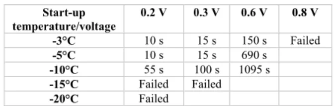
FIGURE 1. Effects of cell voltage and startup temperature on the rapid cold start [5].
In the first category, several researchers have demonstrated that it is possible to start the PEMFC at a subfreezing tem-perature without any assisting solution. Jiang and Wang [86] proposed a potentiostatic startup method, which resulted in a drastic increase in current density of the cell at subfreez-ing temperatures and thus a greater heat generation and a faster cell warmup. Lin et al. [5] also used a potentiostatic startup method and integrated the printed circuit board (PCB) technology to study the current density distributions of the PEMFC. The cell can be rapidly cold-started in 10 s from
−5◦C and 55 s from −10◦C under 0.2 V operating
condi-tions, but the cell failed at −15◦C and −20◦C [89], [90]. Fig. 1 and Table 4 show the effects of cell voltage and startup temperature on the rapid cold start. From Fig. 1 and Table 4, it is concluded that increasing the initial load and the startup temperature could help to lower the cold start time and achieve rapid warmup of the PEMFC [5]. It was shown also that cell voltage decreases 6.0% at the current density of 1.4 Acm2after the successful cold starts of −10◦C, but it decreases 11.4% after the failed cold starts of −15 ◦C. Further, the degradation becomes obvious after the failed cold starts of −20 ◦C at 1.2 A cm2 with the voltage decreases of 15.2%. It was concluded that the PEMFC performance decayed after failed cold starts. Lin et al. [5] optimized the rapid cold start from −20 ◦C by coordination of the hot
reactant gas and the waste heat generation of the PEMFC. A galvanostatic startup method using PCB technology was proposed, and they found that the ability to start the PEMFC was strong at −3 and −5◦C with any degradation, but weak at −7 and −10◦C, and the PEMFC degrades a significant amount after a failed cold start at a low temperature such as −10◦C [91]. Yan et al. [29] found that the PEMFC can be self-started at −5 ◦C if the cell is correctly purged and insulated and that there was no damage while starting up at −10◦C with a current step of 0-100 mA·cm−2, but the cell failed to start with a current step of 0-220 mA·cm−2, with resulting general cell damage [92]. Guo et al. [93] studied cold start with an anode catalytic reaction for different current densities and indicated that the cold start must be moderate because a low current density slows down the startup pro-cess, and a high current density lowers the assisted heating effect. For a faster and a more robust self-start, Ahluwalia and Wang [7] and Silva et al. [94] suggested operating the stack near short circuit conditions, which optimize hydro-gen consumption and increase the production of waste heat. Toyota also used this solution, which consists of short-circuiting the cell to convert the hydrogen energy exclusively into waste heat. Although this method is effective to warm up the PEMFC, short-circuiting the stack can be very dangerous and may cause severe damage to cell components. Addition-ally, no electricity is available for the vehicle [95]. Many studies suggested other methods for starting up the PEMFC including supplying power from the fuel cell to an external load and then increasing the power drawn and the flow rate of the reactant streams while the stack warms up [5], [42], [46], [96]. Sun et al. [96] found that the heating effects due to the catalytic reaction are generally on the same level (on the level of approximately 0.1◦C/s).
The second internal heating method was used by Roberts et al. [84] and Colbow et al. [97]: reactant star-vation, which generates more heat by either decreasing the stoichiometry at constant current [97] or increasing the cur-rent density at constant stoichiometry [84], [97]. Reactant starvation at an electrode results in an increased overvolt-age at that portion, which increases the internal heat that is generated [84]. If the current density is doubled, there is an
TABLE 4.Cold start time at different temperatures [5].
approximate doubling of the heating rate [84], [97]. This method is particularly suitable for starting up a PEMFC from subzero temperatures. In addition, this method allows for the provision of some electrical power output from the fuel cell during startup [84]. Another starting method, disclosed in a Japanese Patent [98], consists of reducing the pres-sure applied to a fuel cell to increase the contact resistance between components in the main body of the stack.
Another interesting internal heating method used by Fuller and Wheeler [31] and Wheeler and Bonville [99] consisted of introducing a dilute mixture of oxygen (O2) with a small
amount of fuel such as hydrogen distributed through the process oxidant flow channel on the cathode side of a fuel cell. The mixture reacted on a catalyst in the air inlet manifold to produce heat, thereby raising the fuel cell temperature from below freezing to a suitable operating temperature [99]. In other studies, oxygen was introduced into the hydrogen-rich anode feed stream and/or hydrogen into the oxygen-hydrogen-rich cathode feed stream to heat the MEA locally at the anode and cathode by the exothermal catalytic reaction between hydrogen and oxygen [93], [100], [101]. In the same context, Hishinuma et al. [102] used dry bottled gases to supply hydro-gen as a fuel and a 79% N2-21% O2synthetic mixture as an
oxidizer. Thompson and Fuss [42] showed that dry reactants would preferably be provided at a higher stoichiometry with air (air bleed) or O2 up to 25% supplied with the anode
reactant, resulting in an exothermic reaction with hydrogen in the presence of the Pt-coated MEA. Thompson and Fuss [42] showed that it is better if the reaction occurs under low pressure conditions because the high flow rate combined with low pressure creates maximum gas velocities through the fuel stack, which improves removal of incident water and thus prevents the freezing of the product or present water. The research reported in [103]–[105] used methanol or ethanol as a reactant by feeding it into the coolant passages during shutdown. At startup, a certain amount of air is fed through the cathode reactant flow field so that the alcohol diffused into the cathode compartment is oxidized, which produces heat and thus increases the fuel cell temperature above freez-ing to a convenient operatfreez-ing temperature. This approach also has the advantage of creating localized starvation [105]. Yan et al. [29] reported many tests to investigate the effects of gas purging, ambient temperature, air stoichiometry, insula-tion, and feed gas temperature on PEMFC startup. The results of these tests are shown in table 5.
As shown, there are different internal heating solutions to warm up the stack, but each method has its drawbacks.
TABLE 5. Cold startup cases [29].
Table 6 shows the advantages and drawbacks for different internal heating solutions.
C. WARMING MECHANISMS
Several heating mechanisms such as heating the bipolar plates or end plates by placing external heaters at the plate locations [106], heating the MEA locally by catalytic reac-tion [31], [79], [100] or passing heated fluid to heat the stack [107], [108] were investigated by some researchers. Khandelwal et al. [36] found that adding an external heat source to the bipolar plates can be effective but more complex to implement than directly heating the end plates. Anode side heating within the end plate is more effective to achieve a uniform heating profile. Heating the MEA with catalytic heating is also effective but can result in structural damage in the MEA [36]. Pre-heating the inlet reactant gas, especially on the anode side, reduces the startup time by 20-30% and thus improves the stack cold start capability [36]. Passing heated coolant can effectively achieve rapid cold startup, even at lower current density operation [36].
Khandelwal et al. [36] indicate that the appropriate heat source is determined by the startup time target and the stack thermal mass. The effectiveness of these various warming mechanisms on the startup time is summarized in Table 7 and Table 8. The last column in Table 7 represents the ratio of the percentage decrease in the startup time and the total heat supplied to the stack [36].
D. CONTROL AND SENSING
At subfreezing temperatures, it is important to detect water freezing to heat up the stack and avoid difficulty and failure of cold startup. Fujita et al. [61], [109] used a controller that detects the absence/presence of the freeze in some crit-ical components of the fuel cell system. When a detected pressure increases and a detected temperature is below a
TABLE 6.Advantages and drawbacks of different internal heating solutions.
given value, the controller prohibits the start of the fuel cell system. The freezing detection can also be performed using a phenomenon specific to the time when water starts to freeze to allow a reduction in the erroneous activation [103]. Takahashi [110] also employed a freezing detection solution comprising a sensor, which detects a parameter for determin-ing if moisture in the fuel cell stack is frozen. Based on a predetermined input such as geographical location, ambient temperature, user usage profile, date, and weather reports, Clingerman et al. [43] presented a method for determining the potential that a freeze condition will exist after the system is shut down.
Control and sensing for thermal/energy management are also very important during the cold start of the fuel cell. To prevent fuel cell temperatures from rising above the limit
TABLE 7. Effect of different heating mechanisms on the startup time (i = 1 A cm2, base condition) [36].
TABLE 8. Effect of passing heated coolant on startup time (Tamb= −20◦C, base conditions) [36]
temperature that might cause damage to the stack, some researchers developed a method to measure the fuel cell temperature directly by placing sensors at one or more sites in the fuel cell, and the fuel cell temperature can be mea-sured indirectly by monitoring the fluid stream temperatures. When the fuel cell temperature approaches the given temper-ature, a cooling fluid flow will be started [46], [72], [111]. In another study, a method to prevent flooding in the fuel cell cathode during low temperature operation was car-ried out [112]. Henao et al. [113] focused on providing an overall control system based on a supervisory architecture to minimize the energy consumption during cold startup of a PEMFC.
V. COLD START STRATEGIES
After reviewing and categorizing the different solutions for fuel cell shutdown and startup, it is important to focus on the strategies corresponding to the possible heating mecha-nisms and energy management during vehicle parking or at
vehicle start. The cold start strategies include the energy and thermal management for a fuel cell system and aim to satisfy the specific targets for cold start performance in terms of startup time and energy requirement. For successful cold startup, purging the fuel cell at shutdown and warming up before starting is undoubtedly the most viable strategy. In this regard, many studies [45], [91], [114], [115] suggested a cold start strategy of PEMFC, which can be illustrated by the following two interaction processes: (1) a purge process to avoid water freezing or (2) a temperature increasing process based on a heating solution. Another strategy proposed by Khandelwal et al. [36] and Sasmito et al. [116] recommended using thermal insulation of the stack to maintain the stack temperature above its freezing point and reduce the startup time. When a freezing condition is detected, they recommend using internal or external heating solutions to warm up the stack at startup. Lin et al. [5] and Henao et al. [113] aimed to optimize the rapid cold start strategy by combination of the heating solution (hot reaction gas, heater) and waste heat generation of the PEMFC. In another study, a rapid and stable cold start strategy was developed. This strategy can simultaneously suppress both ice formation/growth and anode dry-out [117]. Guo et al. [93] proposed to humidify the anode due to the catalytic reaction and to reduce the ohmic resistance of the membrane, which improves the cold startup performance. A current ramping strategy was proposed by Jiang et al. [115]. This strategy requires purging the fuel cell at shutdown and raising the cell temperature and improved water adsorption of the membrane during startup, thereby permitting an aggressive increase in the operating current density with time without forming much ice in the CCL. Zhou et al. [118] proposed a novel cold startup strategy which consists of applying loads to the bordering cells that are still active and concurrently applying external heating to some cells within the stack (load is not applied to the cells that are fully blocked by ice, although these cells can gain heat from neighboring cells). Thanks to this method, the efficiency of the external heating power and the stack self-heating ability are enhanced.
Some researchers suggested considering two main strate-gies according to whether the system uses energy dur-ing vehicle parkdur-ing or mostly at vehicle start. The first, the so-called ‘‘keep warm’’ strategy [13], [43], [74], [80] consists of keeping the system warm to prevent freezing of the stack. Keeping the system warm is ensured by a control and sensing system that manages energy consump-tion during parking. This method needs an intermittent or continuous supply of a low power energy source (from a battery or hydrogen fuel converter) that limits the storage protection time available. This strategy potentially prevents damage caused through freeze and warm up cycles [13]. With the method proposed by Clingerman et al. [43], an energy management system is required to decide whether there is enough fuel and/or battery energy to perform the ‘‘keep it warm’’ strategy. Geographical usage profile information can be considered by the algorithm after deciding the acceptable
FIGURE 2. Comparison of heating energy consumption between thaw at start and keep warm strategies at −20◦C [127].
amount of fuel and battery energy. For example, the algo-rithm could base the decision on the distance to a fueling station. Different heating solutions are known in the art to perform the ‘‘keep warm’’ strategy, including operating the fuel cell in a low power mode (waste heat) and charging the battery [74] or operating electric heaters using fuel cell energy or battery energy [13], [74], or using a catalytic reaction [79], or employing a catalytic burner [80], which does not require great flow rates of fuel and air [80]. More-over, some researchers [116], [119]–[121] have demon-strated that thermal insulation is very important to keep the stack temperature above the minimum operating temperature for a long period and thus to minimize energy consumption during parking time. Insulation of the fuel cell stack can be achieved by different techniques, including use of insulating materials such as foams [122], or a fumed silica system insu-lation [123], or by employing vacuum gaps [124]– [126]. A disadvantage of thermal insulation is that it increases stack weight and volume, which adversely affect the vehicle per-formance and cost [13]. Moreover, if the exposure time of the insulated fuel cell stack to freezing temperatures is extended, the warmup time is longer for the insulated fuel cell stack as the ambient temperature increases [119].
The second, the so-called ‘‘Thaw at Start’’ strategy [13], [77], [118], does not use energy/fuel during vehicle parking and requires a high power source that enables the heating up of the stack at startup. This strategy depends on the mass of the stack and mainly the mass of water that needs to be melted [51]. Haas et al. [41] and Ko and Ju [85] showed that to minimize the energy consumption for the thaw at start strategy and avoid FC damage from ice expansion during
TABLE 9.Comparison between keep warm and thaw at start strategies [13], [127].
FIGURE 3. Solution category chart for PEMFC cold start solutions and strategies.
freezing, it is important to remove water from the FC by purge during shutdown.
Amamou et al. [127] compared the heating energy require-ment for both strategies (Fig. 2) and concluded that the blue curve shows that the energy requirement for the thaw at start strategy depends only on the initial stack temperature and does not vary with vehicle storage time. The red curve shows
a positive slope that can be explained by the fact that the keep-warm strategy requires energy continuously. As seen in Fig. 2, there is a break-even parking duration (D) where the thaw at start strategy becomes more advantageous than the other strategy in terms of heating energy consumption. The break-even parking duration (D) is highly dependent on the ambient temperature [127]. Amamou et al. [127] and Pesaran et al. [13] showed that the keep warm strategy is more effective for a short parking time and for mild subfreezing temperatures but becomes inefficient for long parking time. The thaw at start strategy requires less energy for a long parking time yet requests high power and significant time to start.
Table 9 presents a comparison between keep warm and thaw at start strategies. A solution category chart for PEMFC cold start solutions and strategies is presented in Fig. 3.
VI. CONCLUSION
A PEM fuel cell can be a great eco-friendly alternative power source for vehicles. However, under subfreezing conditions, cell degradation and therefore irreversible performance decay can occur because of ice formation and repetitive thaw/freeze cycles. These problems have limited the further commercial-ization of the PEMFC in cold weather countries. Thus, many improvements have been made to resolve the freeze protec-tion and rapid cold startup problems in PEMFC vehicles.
In this paper, a review of recent research progress on PEMFC cold start problems is presented. Systems and meth-ods for fuel cell shutdown are summarized and classified into two categories: purge solution and material to avoid freezing. Regarding system and solutions for fuel cell startup, differ-ent heating solutions are classified into two main groups, depending on their heating sources, and categorized as inter-nal and exterinter-nal heating methods. The review concludes with a detailed introduction of cold startup strategies, based on an exhaustive survey of journal papers and patents. In this review, modeling studies were not included because such a review was recently presented by Wan et al. [11]. This review allowed regrouping and comparing all research progress on the PEMFC cold start presented in the literature to classify the more interesting cold start solutions and identify problems not addressed and possible directions for future investiga-tions.
Many patents, more so than journal articles, have been published on fuel cell freeze and rapid start, and the group-ing of heatgroup-ing solutions indicates that in the last few years, the researchers focused on internal heating more than external heating. It was concluded that internal heating using gal-vanostatic and potentiostatic solutions is more effective than other heating solutions in term of energy consumption. Many studies concentrated on solutions for fuel cell shutdown and it was shown that vacuum dried solution is the best purge solution in term of water removal. For successful cold startup, purging the fuel cell at shutdown and internal heating at startup is undoubtedly the most viable strategy in term of heating time and energy consumption.
Additional work is still required in several areas, including cold start strategies allowing the use of the catalytic reaction and hybrid systems such as the battery. Existing cold start strategies aim to minimize cold startup time more than startup energy, so more energy management strategies are needed. Repeated freeze/thaw cycles were shown to cause significant performance degradation and decrease fuel cell durability. Therefore, more cold startup strategies are needed to meet durability targets simultaneously with startup time and energy consumption targets. More automotive industrial strategies, including real time methods, need to be developed to pre-dict parking time and energy requirement, reduce energy wastage and increase reliability during subfreezing tempera-tures. Improved techniques to manage water during shutdown and startup; improved temperature uniformity in the stack during heating; and improved heat utilization, cooling, and humidification techniques are needed. It is important also to improve membrane/cell stability under freeze/thaw cycles and membrane conductivity under low humidity conditions.
REFERENCES
[1] N. Marx, L. Boulon, F. Gustin, D. Hissel, and K. Agbossou, ‘‘A review of multi-stack and modular fuel cell systems: Interests, application areas and on-going research activities,’’ Int. J. Hydrogen Energy, vol. 39, pp. 12101–12111, Aug. 2014.
[2] R. Petrone et al., ‘‘A review on model-based diagnosis methodologies for PEMFCs,’’ Int. J. Hydrogen Energy, vol. 38, pp. 7077–7091, Jun. 2013. [3] Y. Yu, H. Li, H. Wang, X.-Z. Yuan, G. Wang, and M. Pan, ‘‘A review on
performance degradation of proton exchange membrane fuel cells during startup and shutdown processes: Causes, consequences, and mitigation strategies,’’ J. Power Sour., vol. 205, pp. 10–23, May 2012.
[4] K. Ettihir, L. Boulon, M. Becherif, K. Agbossou, and H. S. Ramadan, ‘‘Online identification of semi-empirical model parameters for PEM-FCs,’’ Int. J. Hydrogen Energy, vol. 39, pp. 21165–21176, Dec. 2014. [5] R. Lin, Y. Weng, X. Lin, and F. Xiong, ‘‘Rapid cold start of proton
exchange membrane fuel cells by the printed circuit board technology,’’
Int. J. Hydrogen Energy, vol. 39, pp. 18369–18378, Oct. 2014. [6] Y. Wang, K. S. Chen, J. Mishler, S. C. Cho, and X. C. Adroher, ‘‘A review
of polymer electrolyte membrane fuel cells: Technology, applications, and needs on fundamental research,’’ Appl. Energy, vol. 88, no. 4, pp. 981–1007, 2011.
[7] R. K. Ahluwalia and X. Wang, ‘‘Rapid self-start of polymer electrolyte fuel cell stacks from subfreezing temperatures,’’ J. Power Sour., vol. 162, pp. 502–512, Nov. 2006.
[8] Q. Du, B. Jia, Y. Luo, J. Chen, Y. Zhou, and K. Jiao, ‘‘Maximum power cold start mode of proton exchange membrane fuel cell,’’ Int. J. Hydrogen
Energy, vol. 39, pp. 8390–8400, May 2014.
[9] Fuel Cell Technologies Office Multi-Year Research, Development, and Demonstration Plan, The Office of Energy Efficiency And Renewable Energy, USA, 2012.
[10] Y. Luo, Q. Guo, Q. Du, Y. Yin, and K. Jiao, ‘‘Analysis of cold start processes in proton exchange membrane fuel cell stacks,’’ J. Power Sour., vol. 224, pp. 99–114, Feb. 2013.
[11] Z. Wan, H. Chang, S. Shu, Y. Wang, and H. Tang, ‘‘A review on cold start of proton exchange membrane fuel cells,’’ Energies, vol. 7, no. 5, pp. 3179–3203, 2014.
[12] H. Meng and B. Ruan, ‘‘Numerical studies of cold–start phenomena in PEM fuel cells: A review,’’ Int. J. Energy Res., vol. 35, no. 1, pp. 2–14, 2011.
[13] A. A. Pesaran et al., PEM Fuel Cell Freeze and Rapid Startup
Inves-tigation. Golden, CO, USA: National Renewable Energy Laboratory, 2005.
[14] G. Gavello et al., ‘‘Effect of freezing conditions on PEM-FC compo-nents,’’ ECS Trans., vol. 17, no. 1, pp. 359–368, 2009.
[15] K. Han, B. K. Hong, S. H. Kim, B. K. Ahn, and T. W. Lim, ‘‘Influence of anisotropic bending stiffness of gas diffusion layers on the degradation behavior of polymer electrolyte membrane fuel cells under freezing con-ditions,’’ Int. J. Hydrogen Energy, vol. 36, pp. 12452–12464, Sep. 2011.
[16] W. Schmittinger and A. Vahidi, ‘‘A review of the main parameters influ-encing long-term performance and durability of PEM fuel cells,’’ J. Power
Sour., vol. 180, pp. 1–14, May 2008.
[17] E. Pinton, L. Antoni, Y. Fourneron, and S. Rosini, ‘‘Cold start and freeze/thaw cycles effect on PEFMC performances,’’ ECS Trans., vol. 17, no. 1, pp. 251–261, 2009.
[18] Y. S. Kim, S. I. Kim, N. W. Lee, and M. S. Kim, ‘‘Study on a purge method using pressure reduction for effective water removal in polymer electrolyte membrane fuel cells,’’ Int. J. Hydrogen Energy, vol. 40, no. 30, pp. 9473–9484, 2015.
[19] A. Santamaria, H.-Y. Tang, J. W. Park, G.-G. Park, and Y.-J. Sohn, ‘‘3D neutron tomography of a polymer electrolyte membrane fuel cell under sub-zero conditions,’’ Int. J. Hydrogen Energy, vol. 37, no. 14, pp. 10836–10843, 2012.
[20] E. A. Cho et al., ‘‘Characteristics of the PEMFC repetitively brought to temperatures below 0 řC,’’ J. Electrochem. Soc., vol. 150, no. 12, pp. A1667–A1670, 2003.
[21] R. Borup et al., ‘‘Scientific aspects of polymer electrolyte fuel cell durability and degradation,’’ Chem. Rev., vol. 107, no. 10, pp. 3904–3951, 2007.
[22] S. He and M. M. Mench, ‘‘One-dimensional transient model for frost heave in polymer electrolyte fuel cells,’’ J. Electrochem. Soc., vol. 153, no. 9, pp. A1724–A1731, 2006.
[23] E. L. Thompson, J. Jorne, W. Gu, and H. A. Gasteiger, ‘‘PEM fuel cell operation at –20 řC. II. Ice formation dynamics, current distribution, and voltage losses within electrodes,’’ J. Electrochem. Soc., vol. 155, no. 9, pp. B887–B896, 2008.
[24] G.-G. Park et al., ‘‘Analysis on the freeze/thaw cycled polymer elec-trolyte fuel cells,’’ Current Appl. Phys., vol. 10, no. 2, pp. S62–S65, 2010.
[25] R. Mukundan, Y. S. Kim, F. H. Garzon, and B. Pivovar, ‘‘Freeze/thaw effects in PEM fuel cells,’’ ECS Trans., vol. 1, no. 8, pp. 403–413, 2006. [26] K. Tajiri, Y. Tabuchi, and C.-Y. Wang, ‘‘Isothermal cold start of poly-mer electrolyte fuel cells,’’ J. The Electrochem. Soc., vol. 154, no. 2, pp. B147–B152, 2007.
[27] T. J. Dursch, G. J. Trigub, J. F. Liu, C. J. Radke, and A. Z. Weber, ‘‘Non-isothermal melting of ice in the gas-diffusion layer of a proton-exchange-membrane fuel cell,’’ Int. J. Heat Mass Transf., vol. 67, pp. 896–901, Dec. 2013.
[28] S. Hirakata, T. Mochizuki, M. Uchida, H. Uchida, and M. Watan-abe, ‘‘Investigation of the effect of pore diameter of gas diffusion layers on cold start behavior and cell performance of polymer elec-trolyte membrane fuel cells,’’ Electrochim. Acta, vol. 108, pp. 304–312, Oct. 2013.
[29] Q. Yan, H. Toghiani, Y.-W. Lee, K. Liang, and H. Causey, ‘‘Effect of sub-freezing temperatures on a PEM fuel cell performance, startup and fuel cell components,’’ J. Power Sour., vol. 160, pp. 1242–1250, Oct. 2006.
[30] Y. Tabe, M. Saito, K. Fukui, and T. Chikahisa, ‘‘Cold start characteristics and freezing mechanism dependence on start-up temperature in a polymer electrolyte membrane fuel cell,’’ J. Power Sour., vol. 208, pp. 366–373, Jun. 2012.
[31] T. F. Fuller and D. J. Wheeler, ‘‘Start up of frozen fuel cell,’’ U.S. Patent 6 103 410, Aug. 15, 2000.
[32] M. Oszcipok, D. Riemann, U. Kronenwett, M. Kreideweis, and M. Zedda, ‘‘Statistic analysis of operational influences on the cold start behaviour of PEM fuel cells,’’ J. Power Sour., vol. 145, pp. 407–415, Aug. 2005. [33] J. Hou et al., ‘‘Investigation of resided water effects on PEM fuel cell after
cold start,’’ Int. J. Hydrogen Energy, vol. 32, pp. 4503–4509, Dec. 2007. [34] P. Chippar and H. Ju, ‘‘Evaluating cold-start behaviors of end and inter-mediate cells in a polymer electrolyte fuel cell (PEFC) stack,’’ Solid State
Ionics, vol. 225, pp. 85–91, Oct. 2012.
[35] J. Hou, H. Yu, M. Yang, W. Song, Z. Shao, and B. Yi, ‘‘Reversible performance loss induced by sequential failed cold start of PEM fuel cells,’’ Int. J. Hydrogen Energy, vol. 36, pp. 12444–12451, Sep. 2011. [36] M. Khandelwal, S. Lee, and M. M. Mench, ‘‘One-dimensional thermal
model of cold-start in a polymer electrolyte fuel cell stack,’’ J. Power
Sour., vol. 172, pp. 816–830, Oct. 2007.
[37] H. Meng, ‘‘Numerical studies of cold-start phenomenon in PEM fuel cells,’’ Electrochim. Acta, vol. 53, pp. 6521–6529, Sep. 2008.
[38] A. Jo, S. Lee, W. Kim, J. Ko, and H. Ju, ‘‘Large-scale cold-start simula-tions for automotive fuel cells,’’ Int. J. Hydrogen Energy, vol. 40, no. 2, pp. 1305–1315, 2015.
[39] R. H. Barton, T. D. Uong, C. J. Schembri, and G. A. Skinner, ‘‘Fuel cell purging method and apparatus,’’ U.S. Patent 6 960 401, Nov. 1, 2005.
[40] Y. Wang, P. P. Mukherjee, J. Mishler, R. Mukundan, and R. L. Borup, ‘‘Cold start of polymer electrolyte fuel cells: Three-stage startup characterization,’’ Electrochim. Acta, vol. 55, no. 8, pp. 2636–2644, Mar. 2010.
[41] H. Haas, S. Chor, L.-I. Cosacescu, R. Rahmani, and C. Richards, ‘‘Systems and methods for fuel cell shutdown,’’ U.S. Patent 0 121 322, Jun. 8, 2006.
[42] E. Thompson and R. Fuss, ‘‘Control system and method for starting a frozen fuel cell,’’ U.S. Patent 0 033 396, Feb. 19, 2004.
[43] B. J. Clingerman et al., ‘‘Fuel cell system water management strategy for freeze capability,’’ U.S. Patent 0 298 289, Dec. 2007.
[44] H.-Y. Tang, A. D. Santamaria, J. Bachman, and J. W. Park, ‘‘Vacuum-assisted drying of polymer electrolyte membrane fuel cell,’’ Appl. Energy, vol. 107, pp. 264–270, Jul. 2013.
[45] J. St-Pierre, J. Roberts, K. Colbow, S. Campbell, and A. Nelson, ‘‘PEMFC operational and design strategies for sub zero environments,’’ J. New
Mater. Electrochem. Syst., vol. 8, pp. 163–176, 2005.
[46] J. Roberts, J. St-Pierre, M. van der Geest, A. Atbi, and N. Fletcher, ‘‘Methods for improving the cold starting capability of an electrochemical fuel cell,’’ U.S. Patent 0 077 487, Apr. 24, 2003.
[47] E. Pinton, Y. Fourneron, and A. Guillermo, ‘‘Method for storing a fuel cell at negative temperature,’’ U.S. Patent 0 014 547, Jan. 20, 2011.
[48] N. J. Fletcher, G. A. Boehm, and E. G. Pow, ‘‘Method and apparatus for commencing operation of a fuel cell electric power generation sys-tem below the freezing sys-temperature of water,’’ U.S. Patent 5 798 186, Aug. 25, 1998.
[49] K. Tajiri, C.-Y. Wang, and Y. Tabuchi, ‘‘Water removal from a PEFC during gas purge,’’ Electrochim. Acta, vol. 53, pp. 6337–6343, Sep. 2008.
[50] K. Tajiri, Y. Tabuchi, F. Kagami, S. Takahashi, K. Yoshizawa, and C.-Y. Wang, ‘‘Effects of operating and design parameters on PEFC cold start,’’ J. Power Sour., vol. 165, pp. 279–286, Feb. 2007.
[51] P. Y. J. Yip, J. Bellerive, and S. J. Lee, ‘‘Drying method for fuel cell stacks,’’ U.S. Patent 7 659 017, Feb. 9, 2010.
[52] J. St-Pierre, N. Y. Jia, M. van der Geest, A. Atbi, and H. Haas, ‘‘Methods and apparatus for improving the cold starting capability of a fuel cell,’’ U.S. Patent 0 186 093, Oct. 2, 2003.
[53] T. Skiba, ‘‘Vacuum assisted startup of a fuel cell at sub-freezing temper-ature,’’ U.S. Patent 7 112 379, Sep. 26, 2006.
[54] R. L. Fuss, ‘‘Freeze-protecting a fuel cell by vacuum drying,’’ U.S. Patent 6 358 637, Mar. 19, 2002.
[55] S. Ge and C.-Y. Wang, ‘‘Characteristics of subzero startup and water/ice formation on the catalyst layer in a polymer electrolyte fuel cell,’’
Elec-trochim. Acta, vol. 52, pp. 4825–4835, Apr. 2007.
[56] S. Ge and C.-Y. Wang, ‘‘Cyclic voltammetry study of ice formation in the PEFC catalyst layer during cold start,’’ J. Electrochem. Soc., vol. 154, no. 12, pp. B1399–B1406, 2007.
[57] S. Ge and C.-Y. Wang, ‘‘In situ imaging of liquid water and ice formation in an operating PEFC during cold start,’’ Electrochem. Solid-State Lett., vol. 9, no. 11, pp. A499–A503, 2006.
[58] K. Tajiri and C.-Y. Wang, ‘‘Cold start of polymer electrolyte fuel cells,’’ in
Modeling and Diagnostics of Polymer Electrolyte Fuel Cells. Columbia, SC, USA: Springer, 2010, pp. 89–128.
[59] R. L. Borup, J. Davey, F. Garzon, D. Wood, P. Welch, and K. More, ‘‘PEM fuel cell durability with transportation transient operation,’’ ECS Trans., vol. 3, no. 1, pp. 879–886, 2006.
[60] P. K. Sinha and C.-Y. Wang, ‘‘Gas purge in a polymer electrolyte fuel cell,’’ J. Electrochem. Soc., vol. 154, no. 11, pp. B1158–B1166, 2007. [61] N. Fujita et al., ‘‘Fuel cell system and method of starting the frozen fuel
cell system,’’ EP Patent 1 429 409, Dec. 26, 2012.
[62] S. C. Mohapatra, ‘‘Fuel cell and fuel cell coolant compositions,’’ U.S. Patent 7138199, Nov. 21, 2006.
[63] J. St-Pierre, S. Campbell, M. Watson, M. Sexsmith, M. Derflinger, and G. Hornburg, ‘‘Antifreeze cooling subsystem,’’ U.S. Patent 0 224 201, Nov. 11, 2004.
[64] B. Wenderoth and B. Flaig, ‘‘Coolant based on azole derivatives contain-ing 1,3-propanediol for fuel cell coolcontain-ing systems,’’ U.S. Patent 0 027 782, Feb. 9, 2006.
[65] D. G. Converse and F. J. Mueller, ‘‘Saturated vapor block for frozen fuel cell power plant,’’ U.S. Patent 8 835 067, Sep. 16, 2014.
[66] J. Ko, W.-G. Kim, Y.-D. Lim, and H. Ju, ‘‘Improving the cold-start capa-bility of polymer electrolyte fuel cells (PEFCs) by using a dual-function micro-porous layer (MPL): Numerical simulations,’’ Int. J. Hydrogen
[67] J. Ko and H. Ju, ‘‘Numerical evaluation of a dual-function microporous layer under subzero and normal operating temperatures for use in auto-motive fuel cells,’’ Int. J. Hydrogen Energy, vol. 39, pp. 2854–2862, Feb. 2014.
[68] F. Barbir, A. Husar, J. K. Neutzler, Y. Ngu, and R. Snipas, ‘‘Freeze tolerant fuel cell system and method,’’ WO Patent 2000 065 676, Nov. 2, 2000.
[69] C. A. Reiser and F. F. Sribnik, ‘‘Fuel cell stack melting of coolant water during frozen startup,’’ U.S. Patents 2004 073 133, Aug. 26, 2006.
[70] D. Yang, E. A. Ballinger, and D. A. Condit, ‘‘Method and apparatus for the operation of a cell stack assembly during subfreezing temperatures,’’ U.S. Patent 6 596 426, Jul. 22, 2003.
[71] S. Dewey, ‘‘FCPM freeze start heater,’’ U.S. Patent 2005 0 277 003, Dec. 15, 2005.
[72] K. C. Desrosiers, A. LaVen, and D. W. Skinkle, ‘‘Systems and methods for starting and operating fuel cell systems in subfreezing temperatures,’’ U.S. Patent 8 492 044, Jul. 23, 2013.
[73] K. Wakabayashi and Y. Iwasaki, ‘‘Freeze protected fuel cell system,’’ Google Patent EP 1 414 090 A1, Apr. 28, 2004.
[74] W. S. Wheat, M. A. Meltser, and D. A. Masten, ‘‘Fuel cell energy man-agement system for cold environments System for cold environment,’’ Google Patent US 6 727 013 B2, Apr. 27, 2004.
[75] H. Abe, Y. Asano, and M. Kai, ‘‘Start control device for fuel cell system,’’ U.S. Patent 6 815 103, Nov. 9, 2004.
[76] C. A. Reiser, ‘‘Battery-boosted, rapid startup of frozen fuel cell,’’ U.S. Patent 6 777 115, Aug. 17, 2004.
[77] S. D. Burch, B. J. Clingerman, A. B. Alp, D. A. Arthur, D. Wexel, and M. Fasse, ‘‘Fuel cell startup method for fast freeze startup,’’ U.S. Patent 2014 0 342 258, Nov. 20, 2014.
[78] N. Matsuoka, ‘‘Warm-up of fuel cell power plant with polymer elec-trolyte,’’ WO Patent 2003 061 045, Apr. 22, 2004.
[79] K. Korytnikov and P. Novak, ‘‘Method and apparatus for cold-starting a PEM fuel cell (PEMFC), and PEM fuel cell system,’’ U.S. Patent 2005 0 227 126, Oct. 13, 2005.
[80] R. J. Assarabowski, W. T. Unkert, L. A. Bach, A. P. Grasso, and B. C. Olsommer, ‘‘Method and apparatus for preventing water in fuel cell power plants from freezing during storage,’’ U.S. Patent 6 797 421, Sep. 28, 2004.
[81] N. M. C. LTD, ‘‘Warm-up system of fuel cellsolved,’’ Google Patent US 2004/0 013 915 A1, Jan. 22, 2004.
[82] N. M. C. LTD, ‘‘Fuel cell system,’’ Google Patent US 6 329 089 B1, Dec. 11, 2001.
[83] T. A. Johnson and M. P. Kanouff, ‘‘Development of a hydrogen catalytic heater for heating metal hydride hydrogen storage systems,’’ Int. J.
Hydro-gen Energy, vol. 37, pp. 2304–2319, Feb. 2012.
[84] J. Roberts, M. van der Geest, J. St-Pierre, D. P. Wilkinson, A. Lee, and S. Moroz, ‘‘Method and apparatus for increasing the temperature of a fuel cell,’’ Google Patent, 2001.
[85] J. Ko and H. Ju, ‘‘Comparison of numerical simulation results and exper-imental data during cold-start of polymer electrolyte fuel cells,’’ Appl.
Energy, vol. 94, pp. 364–374, Jun. 2012.
[86] F. Jiang and C.-Y. Wang, ‘‘Potentiostatic start-up of PEMFCs from sub-zero temperatures,’’ J. Electrochem. Soc., vol. 155, no. 7, pp. B743–B751, 2008.
[87] F. Jiang, W. Fang, and C.-Y. Wang, ‘‘Non-isothermal cold start of poly-mer electrolyte fuel cells,’’ Electrochim. Acta, vol. 53, pp. 610–621, Dec. 2007.
[88] H. Meng, ‘‘Numerical analyses of non-isothermal self-start behaviors of PEM fuel cells from subfreezing startup temperatures,’’ Int. J. Hydrogen
Energy, vol. 33, pp. 5738–5747, Oct. 2008.
[89] K. Jiao, I. E. Alaefour, G. Karimi, and X. Li, ‘‘Simultaneous measurement of current and temperature distributions in a proton exchange mem-brane fuel cell during cold start processes,’’ Electrochim. Acta, vol. 56, pp. 2967–2982, Mar. 2011.
[90] K. Jiao, I. E. Alaefour, G. Karimi, and X. Li, ‘‘Cold start characteristics of proton exchange membrane fuel cells,’’ Int. J. Hydrogen Energy, vol. 36, pp. 11832–11845, Sep. 2011.
[91] R. Lin, Y. Weng, Y. Li, X. Lin, S. Xu, and J. Ma, ‘‘Internal behavior of segmented fuel cell during cold start,’’ Int. J. Hydrogen Energy, vol. 39, pp. 16025–16035, Sep. 2014.
[92] S. G. Kandlikar and Z. Lu, ‘‘Fundamental research needs in combined water and thermal management within a proton exchange membrane fuel cell stack under normal and cold-start conditions,’’ J. Fuel Cell Sci.
Technol., vol. 6, no. 4, p. 044001, 2009.
[93] Q. Guo, Y. Luo, and K. Jiao, ‘‘Modeling of assisted cold start processes with anode catalytic hydrogenŰoxygen reaction in proton exchange membrane fuel cell,’’ Int. J. Hydrogen Energy, vol. 38, pp. 1004–1015, Jan. 2013.
[94] R. E. Silva et al., ‘‘Proton exchange membrane fuel cell operation and degradation in short-circuit,’’ Fuel Cells, vol. 14, no. 6, pp. 894–905, 2014.
[95] K. Sekizawa, N. Kitamura, K. Manabe, Y. Nonobe, M. Kizaki, and K. Kojima, ‘‘Recent advances in TOYOTA FCHV-adv fuel cell system,’’
ECS Trans., vol. 33, no. 1, pp. 1947–1957, 2010.
[96] S. Sun et al., ‘‘Catalytic hydrogen/oxygen reaction assisted the proton exchange membrane fuel cell (PEMFC) startup at subzero temperature,’’
J. Power Sour., vol. 177, pp. 137–141, Feb. 2008.
[97] K. M. Colbow et al., ‘‘Method and apparatus for operating an electrochemical fuel cell with periodic reactant starvation,’’ U.S. Patent 6 472 090, Oct. 29, 2002.
[98] T. Takahshi, Fuel Cell Power Generating System. Office Européen Des Brevets, 1995.
[99] D. J. Wheeler and L. J. Bonville, ‘‘Start up of proton exchange membrane fuel cell,’’ U.S. Patent 6 127 056, Oct. 3, 2000.
[100] J. A. Rock and L. B. Plant, ‘‘Cold start-up of a PEM fuel cell,’’ U.S. Patent 6358638, Mar. 19, 2002.
[101] J. A. Rock and L. B. Plant, ‘‘Method of cold start-up of a PEM fuel cell,’’ EP Patent 1 113 516, Apr. 28, 2004.
[102] Y. Hishinuma, T. Chikahisa, F. Kagami, and T. Ogawa, ‘‘The design and performance of a PEFC at a temperature below freezing,’’ JSME Int. J. B
Fluids Thermal Eng., vol. 47, no. 2, pp. 235–241, 2004.
[103] A. Morita, J. Yamamoto, K. Ueda, and T. Mukaide, ‘‘Freezing detection method for fuel cell,’’ U.S. Patent 8 430 560, Apr. 30, 2013.
[104] T. F. Fuller and D. J. Wheeler, ‘‘Start up of cold fuel cell,’’ U.S. Patent 6 068 941, May 30, 2000.
[105] W. Tillmetz, D. P. Wilkinson, K. M. Colbow, and J. St-Pierre, ‘‘Fuel cell system with improved starting capability,’’ U.S. Patent 6 410 175, Jun. 25, 2002.
[106] M. Sundaresan and R. M. Moore, ‘‘Polymer electrolyte fuel cell stack thermal model to evaluate sub-freezing startup,’’ J. Power Sour., vol. 145, pp. 534–545, Aug. 2005.
[107] H. T. Couch and F. Sribnik, ‘‘Configuration enabling rapid fuel cell power from sub-freezing initial condition,’’ U.S. Patent 6 773 840, Aug. 10, 2004.
[108] G. S. Saloka and J. A. Adams, ‘‘System and method for rapid preheating of an automotive fuel cell,’’ U.S. Patent 6 916 566, Jul. 12, 2005. [109] N. Fujita et al., ‘‘Fuel cell system and method of controlling the same fuel
cell system,’’ U.S. Patent 7 976 999, Jul. 12, 2011.
[110] N. Takahashi, ‘‘Fuel cell stack defrosting,’’ WO Patent 2004 004 035, Jan. 8, 2004.
[111] E. L. Thompson and Y. Zhang, ‘‘Method to begin coolant circulation to prevent MEA overheating during cold start,’’ U.S. Patent 7 393 602, Jul. 1, 2008.
[112] D. H. Lee et al., ‘‘Method for controlling operation of fuel cell at low temperature,’’ U.S. Patent 8 518 593, Aug. 27, 2013.
[113] N. Henao, S. Kelouwani, K. Agbossou, and Y. Dubé, ‘‘Proton exchange membrane fuel cells cold startup global strategy for fuel cell plug-in hybrid electric vehicle,’’ J. Power Sour., vol. 220, pp. 31–41, Dec. 2012.
[114] L. Jia, Z. Tan, M. Kang, and Z. Zhang, ‘‘Experimental investiga-tion on dynamic characteristics of proton exchange membrane fuel cells at subzero temperatures,’’ Int. J. Hydrogen Energy, vol. 39, pp. 11120–11127, Jul. 2014.
[115] F. Jiang, C.-Y. Wang, and K. S. Chen, ‘‘Current ramping: A strategy for rapid start-up of PEMFCs from subfreezing environment,’’ J.
Elec-trochem. Soc., vol. 157, no. 3, pp. B342–B347, 2010.
[116] A. P. Sasmito, T. Shamim, and A. S. Mujumdar, ‘‘Passive thermal man-agement for PEM fuel cell stack under cold weather condition using phase change materials (PCM),’’ Appl. Thermal Eng., vol. 58, pp. 615–625, Sep. 2013.
[117] G. Gwak, J. Ko, and H. Ju, ‘‘Numerical investigation of cold-start behav-ior of polymer-electrolyte fuel-cells from subzero to normal operating temperatures—Effects of cell boundary and operating conditions,’’ Int.
J. Hydrogen Energy, vol. 39, no. 36, pp. 21927–21937, 2014.
[118] Y. Zhou, Y. Luo, S. Yu, and K. Jiao, ‘‘Modeling of cold start processes and performance optimization for proton exchange membrane fuel cell stacks,’’ J. Power Sour., vol. 247, pp. 738–748, Feb. 2014.
[119] B. Lin, ‘‘Thermal control of fuel cell for improved cold start,’’ U.S. Patent 7 534 511, May 19, 2009.
![TABLE 1. Summary of model results and critical parameters for the cold start [36].](https://thumb-eu.123doks.com/thumbv2/123doknet/14606223.731784/3.864.445.804.135.773/table-summary-model-results-critical-parameters-cold-start.webp)
![FIGURE 1. Effects of cell voltage and startup temperature on the rapid cold start [5].](https://thumb-eu.123doks.com/thumbv2/123doknet/14606223.731784/6.864.446.805.571.857/figure-effects-cell-voltage-startup-temperature-rapid-start.webp)
![TABLE 5. Cold startup cases [29].](https://thumb-eu.123doks.com/thumbv2/123doknet/14606223.731784/8.864.448.803.142.792/table-cold-startup-cases.webp)
![TABLE 7. Effect of different heating mechanisms on the startup time (i = 1 A cm 2 , base condition) [36].](https://thumb-eu.123doks.com/thumbv2/123doknet/14606223.731784/9.864.60.417.137.512/table-effect-different-heating-mechanisms-startup-time-condition.webp)
![FIGURE 2. Comparison of heating energy consumption between thaw at start and keep warm strategies at −20 ◦ C [127].](https://thumb-eu.123doks.com/thumbv2/123doknet/14606223.731784/10.864.59.417.89.470/figure-comparison-heating-energy-consumption-thaw-start-strategies.webp)
