HAL Id: hal-02475589
https://hal.inria.fr/hal-02475589
Submitted on 12 Feb 2020
HAL is a multi-disciplinary open access
archive for the deposit and dissemination of
sci-entific research documents, whether they are
pub-lished or not. The documents may come from
teaching and research institutions in France or
abroad, or from public or private research centers.
L’archive ouverte pluridisciplinaire HAL, est
destinée au dépôt et à la diffusion de documents
scientifiques de niveau recherche, publiés ou non,
émanant des établissements d’enseignement et de
recherche français ou étrangers, des laboratoires
publics ou privés.
meso-structured materials: design, modeling by
homogenization and simulation
Félix Vanneste, Olivier Goury, Jonas Martinez, Sylvain Lefebvre, Hervé
Delingette, Christian Duriez
To cite this version:
Félix Vanneste, Olivier Goury, Jonas Martinez, Sylvain Lefebvre, Hervé Delingette, et al.. Anisotropic
soft robots based on 3D printed meso-structured materials: design, modeling by
homogeniza-tion and simulahomogeniza-tion.
IEEE Robotics and Automation Letters, IEEE 2020, 5 (2), pp.2380-2386.
�10.1109/LRA.2020.2969926�. �hal-02475589�
Anisotropic soft robots based on 3D printed
meso-structured materials: design, modeling by
homogenization and simulation
F´elix Vanneste
1,2, Olivier Goury
1,2, Jon`as Mart´ınez
3, Sylvain Lefebvre
3, Herve Delingette
4, Christian Duriez
1,2Abstract—In this paper, we propose to use new 3D-printed meso-structured materials to build soft robots and we present a modeling pipeline for design assistance and control. These meta-materials can be programmed before printing to target specific mechanical properties, in particular heterogeneous stiffness and anisotropic behaviour. Without changing the external shape, we show that using such meta-material can lead to a dramatic change in the kinematics of the robot. This highlights the importance of modeling. Therefore, to help the design and to control soft robots made of these meso-structured materials, we present a modeling method based on numerical homogenization and Finite Element Method (FEM) that captures the anisotropic deformations. The method is tested on a 3 axis parallel soft robot initially made of silicone. We demonstrate the change in kinematics when the robot is built with meso-structured materials and compare its behavior with modeling results.
Index Terms—Soft Robot Materials and Design, Simulation and Animation, Additive Manufacturing, Soft Robot Applica-tions, Kinematics
I. INTRODUCTION
T
HE aim of soft robotics is to take advantage of the natural compliance of the material(s) that make up the robot in order to simplify its design, reduce the risk of damage and provide inherent control. In most cases of the state of the art, the production of soft robots is done by 3D-printing a mold in which silicone is casted. It creates a soft structure of the desired geometry, that is actuated to make the robot move. However, control over the properties of the resulting material remains limited: changing the rigidity requires changing the silicone. Yet, in the process of designing a soft robot, it seems important to better control compliance and even ideally to program it with heterogeneities in the structure to obtain a desired behavior.Metamaterials seem ideal for achieving this ability as they are engineered to have properties that are not found in nat-urally occurring materials. These properties are obtained by a particular micro-structuring of the material or by the use of composite materials. They are used for optic, acoustic or thermal applications, but in this study we make use of them for their mechanical properties.
As defined in [1] mechanical metamaterials succeed by carefull design of its building blocks and by exploiting motion, deformations, stresses and mechanical energy in achieving any
1 DEFROST team, Inria Lille-Nord Europe, France 2 University of Lille - CRIStAL UMR CNRS 9189, France 3INRIA, Universit´e de Lorraine, Nancy, France
4INRIA, Universit´e Cˆote d’Azur, Sophia Antipolis, France
combination of linear elastic coefficients that is not forbidden by thermodynamics.
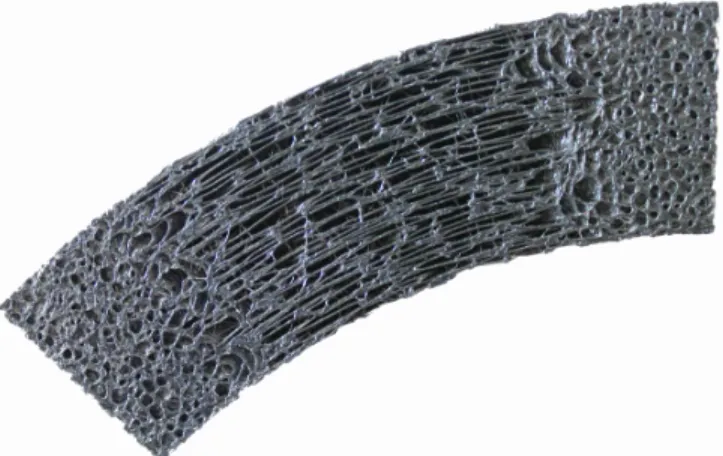
Fig. 1: Example of a stochastic foam with varying flexibility 3D printed with IceSL
Regarding fabrication, mechanical metamaterials have been used already to design soft robots with various kinds of approaches such as Origami, bi-stable or auxetic structures [2, 3, 4, 5]. Unfortunately, these metamaterials do not really allow to freely distribute the stiffness and are not all printable with classical 3D printers. Furthermore, the design of such structures is difficult without reliable computer assisted design solution.
In this work, we use a new method based on a specific sub-type of mechanical metamaterials, that has never been used for the fabrication of soft robots. This specific type of mechanical metamaterials are called linear mechanical meta-materials. They consist on varying the mechanical properties along the shape by using pattern and in this way controlling the heterogeneities in the structure.
The linear mechanical metamaterials that can be casted or 3D printed are mainly made using building blocks as shown in the works of [6] [7] [8]. In practice, the mechanical properties of the fundamental blocks are precisely characterized and classified into ”families”. These blocks are then placed on the shape to obtain a distribution of the mechanical properties.
One drawback of this method is its precision limited by the block scale and the transition between the different properties is not always smooth.
A completely different approach was introduced by [9] and refined with [10] and [11]. Families of blocks are not
used anymore but instead a stochastic foam – Voronoi foams or k-nearest foams – allowing to grade more efficiently and smoothly the change of mechanical properties. An example of such structure is displayed in Fig. 1. In this paper, we propose to use that kind of 3D-printed meso-structured foam for the structure of the soft robot since these are easy to print with an affordable standard 3D-printer and, using the software IceSL, allows a great freedom for giving the resulting material a desired heterogeneity, stiffness or anisotropy.
For design and control, it is important to model these structures to predict their deformations under actuation. This is challenging since their geometry is very intricate and complex. It makes the use of standard numerical methods such as the FEM impractical. In this paper, we propose to solve this issue by using a method of numerical homogenization. This is a well-known method in the computational mechanics community (see for example [12, 13, 14]), which is used to model materials that are heterogeneous at a small scale. An average macroscopic response is computed from a representa-tive volume element (RVE), and this information allows to find the homogenized constitutive law of the macroscopic material. Contributions
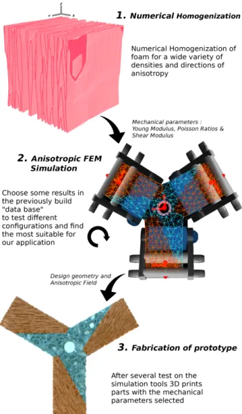
In this paper, we provide a new way of designing soft robots using a programmed metamaterial made of stochastic foam. We demonstrate that this metamaterial can radically change the kinematics of a soft robot without changing its external shape. To model this behavior, we provide an adapted homogenization technique that results in an anisotropic con-stitutive law. We model anisotropy for deformations with large displacement. Then we evaluate the results on a 3 axis parallel soft robot that displays specific behaviours due to the meso-structured material. We show that it corresponds to the kinematics obtained with the real-time simulated anisotropic model. The pipeline is displayed in Fig. 2.
II. SOFT ROBOTS MADE OF STOCHASTIC FOAM In this section we present the fabrication and the pro-gramming of the stochastic foam as well as the associated homogenization technique.
A. Direct fabrication with 3D printing
For the fabrication of the metamaterial, we are using only fused filament fabrication (FFF) printing technique and an ex-isting technique for programming stiffness through stochastic foam. To slice our parts before printing and to put the right in-ternal shape for a desire property we use IceSL1which include features allowing to reproduce the work presented in [9],[10] and [11]. This slicer has many interesting options including the ability to ”paint” on a given shape a desired flexibility and the directions in which the densities are increased or reduced, Fig. 1 show an example of part produced by IceSL.
In practice, the soft structures used for this paper are 3D printed with a basic desktop 3D printer (Prusa i3 MKS) with a thermoplastic polyurethane (TPU) called NinjaFlex
1IceSL: https://icesl.loria.fr
Fig. 2: Workflow proposed in the paper: from the homoge-nization of the mechanical properties of the meso-structure, through the design of a robot on simulation, to the fabrication of the robot with a 3D-printer.
(Shore Hardness: 85A and a tensile modulus of 12MPa : data from the constructor) with 1.75 mm of diameter. We print with a layer thickness of 0.3 mm and a print speed of 25 mm/sec. We choose this TPU in particular because it is inherently compliant. It is one of the only commercially available filament for FFF 3D printing with low shore hardness and, printed as a stochastic foam, we obtain great deformations without having to put to much load.
In this paper, we will use the foam with two different ”degrees” of anisotropy. As defined in [11], the scalar pa-rameter γ ∈ [0, 1], called degree of anisotropy, is one of the parameters defining a convex distance function that is used in turn to define the Voronoi diagram (used later to generate the foam geometry) of a set of points in R3. In terms of linear elastic behavior, decreasing γ decreases the E1 (where 1,2,3
E2, E3, since the Voronoi faces become comparatively more
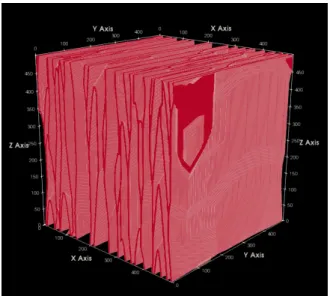
elongated in the direction 2 and 3 compared to the 1 direction. More details about the foam generation can be found in [11]. In this paper we will focus on the two extremes values of γ : either giving a transverse isotropic (see following section for the formal definitions) foam with 0.1 or isotropic with 1. We can see in Fig. 3 an example of a meso-structure with a γ of 0.1.
Fig. 3: Example of a foam representative volume used to find the homogenised properties. Here the foam shows a strong transverse isotropy: the degree of anisotropy is 0.1
B. Numerical homogenization to determine the parameters for the constitutive law of the meso-structure
The complex geometry of the 3D-printed foam makes it intractable to simulate using standard FE modeling. It would require a very dense mesh. Instead, we propose to consider the foam as a continuum, with an anisotropic elastic constitutive law based on homogenized mechanical parameters. To obtain the numerical homogenization of the parametrized foam , similarly to [11], we used the open source software CrAFT2.
Given a sample, this software uses Fast Fourier Transform (FFT) to compute the homogenized mechanical parameters. This homogenization leads to an anisotropic constitutive law, with different Poisson ratios, shear and Young Moduli in dif-ferent directions, given the densities of the foam as illustrated in Fig. 4.
We approximate this data by considering that our material is either totally transverse or totally isotropic. For the homog-enized samples that are nearly transverse we take the mean of Young’s moduli y and z and for the isotropic case we do the mean of Young’s moduli x,y and z.
On top of this approximation we also have to be aware of the imperfection of the printing technique. In practice, FFF induces a natural orthotropy along the printing direction, which is not taken into account during the homogenization. Using
2http://craft.lma.cnrs-mrs.fr
Fig. 4: Data from homogenization of 4 samples with a relative density varying between 9 to 34%. A and B are for the transverse isotropic case and C correspond to the isotropic case. The Young’s modulus shown here are normalized to a base isotropic material having a Young’s modulus E = 1 and Poisson’s ratio v = 0.3
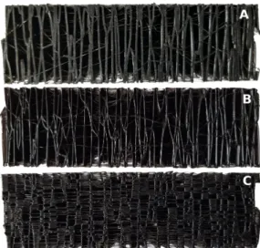
a flexible filament adds new problems that can be observed in Fig. 5. One of the main issue is oozing: it adds extra matter and render the side a little bit stiffer. Also because the flexible filament stick really well to the building plate the first layer of every pieces is a bit stiffer, this with the oozing create pieces which are stratified. Depending of the size and configuration of the part, this can influence the final behavior greatly. These limitations of 3D printing are not yet taken into account during the homogenization. But in practice, we observed that errors in the homogenization data of stochastic foams remain acceptable. Thanks to this step, an anisotropic constitutive law is obtained and we use it to model the robot.
III. MODEL IMPLEMENTATION / SIMULATION In this section, we present how anisotropic soft robots are simulated using non-linear FEM models and the properties
Fig. 5: Different faces of a same beam showing the differences added due to the printing technique. The beam was printed vertically from A being the first layer to B the last. —A We can see that the filament deposit is broader. —B We clearly see the difference with the first layer —C Due to oozing the sides are rigidified
used to simulate the soft robot made of stochastic foam.
A. Soft Robots Finite Element Model
For the FEM, we rely on the framework SOFA3. For the
modeling of the deformations we use Newton’s second law: M (q) ˙v = P (t) − F (q, v) + HTλ (1) where q is the vector of position of the FEM nodes, v is the vector of velocity, M (q) is the mass matrix, P gathers external forces, F accounts for internal forces (depending on the material the soft robots is made of), and HTλ is the
vector of constraint forces contributions, which are typically generated when an actuator applies force on the soft robot [15].
To model metamaterials we particularly need to focus on the internal forces F . It is in F that the material properties are taken into account and it is here that we will adapt the constitutive elements (here tetrahedra) properties depending on its position in the mesh.
When soft robots are made of homogeneous material like silicone, the stress-strain relationship within the material is nonlinear. The constitutive law reproducing its behaviour is typically hyperelastic, but assuming a linear elastic relation-ship with a corotational formulation can lead to good results as long as the material large deformations are mostly large rotations [16]. This is what we will use in this paper.
The constitutive law allows to compute the internal force vector F through the integration of partial differential equa-tions coming from continuum mechanics. It means that the material is supposed to form a continuum. For the stochastic
3wwww.sofa-framework.org
foams, the homogenization step described in the previous section provides a constitutive law of a virtual continuum material that would have the same properties. The material parameters are: Young modulus, Poisson ratio and the direc-tion of anisotropy
B. Anisotropy
Mechanical metamaterials induce new or different behaviors and responses to stimuli that differ from normal isotropic material (e.g: homogeneous material having the same mechan-ical properties along each axis), we call that phenomenon anisotropy. In such case, the material has a characteristic orientation.
To describe anisotropy mathematically we need to define the relation between the stress ε and strain σ. As mentioned in the previous section we use linear elasticity as constitutive law to describe this relation. Hooke’s law considers that the strain is directly proportional to the stress, which is a good approximation for small deformations (even in case of large displacements):
σ = C ε (2)
Here C is a fourth order tensor, known as the elastic stiffness tensor. C must have several symmetries allowing to write the previous components of relation (2) in Voigt notation as follow : σ = σ11 σ22 σ33 σ23 σ13 σ12 ε = ε11 ε22 ε33 2ε23 2ε13 2ε12 C = C11 . . . C16 .. . . .. C16 . . . C66 (3)
There are 21 constants (C11, C12 ... C66) in matrix C to
describe any kind of material. From this general definition of stress-strain relation, we will investigate specific case of anisotropic linear elastic material (2), to characterize our material with less material constants.
Indeed thanks to material symmetries we will have a reason-able number of parameters and it will ease its implementation later in our framework. There are 3 main cases : orthotropic (three mutually perpendicular symmetry planes) , transverse isotropic and cubic. The one we will focus on here is trans-verse isotropic which is a special case of an orthotropic solid that contains a plane of isotropy (this implies that the solid can be rotated with respect to the loading direction about one axis without measurable effect on the solid’s response), Fig. 3 is an example of a shape with this characteristic. Here with e3 perpendicular to this symmetry plane we have an elastic
stiffness matrix with the form: C11 C12 C13 0 0 0 C11 C13 0 0 0 C33 0 0 0 sym C44 0 0 C44 0 (C11− C12)/2 (4)
Where we can defined all Cij thanks to 5 mechanical
constants (define here in an orthogonal frame 1,2,3) that have been previously determined thanks to the homogenization method presented in section II.B:
• A transversal (E1 = E2 = Et) and longitudinal (E3 =
El) Young’s moduli describing the 2 different stiffness
of the metamaterial. To represent them more easily we can look at Fig. 3 where we can intuitively see the longitudinal stiffness in the X axis which is different from the transverse stiffness of axis Y and Z.
• A transversal poisson ratio (ν12= ν21= νt), a
transver-sal longitudinal poisson ratio (ν13= ν23= νtl) and with
it we can determine the longitudinal transverse poisson ratio (ν31 = ν32 = νlt = νtlEl/Et). Poisson’s ratio νij
gives the contraction in direction j when the extension is applied in direction i.
• µl= µ23= µ13which is the longitudinal shear modulus
C. Implementation
To implement the previously defined elastic stiffness tensor into our simulation framework, we optimize it in order to reduce the computation cost. We decompose the tensor thanks to its eigen values as described in the work of [17].
The framework we are using – SOFA – now include a com-ponent allowing us to simulate transverse isotropic material.
With it, once the homogenization is computed with the density and anistropy properties of the stochastic foam, we fill the elastic stiffness tensor of each element with the homogenized properties of the Young’s moduli, Poisson ratios and directions of anisotropy. The resulting simulation is quite fast – around 20 frames per second – for the example presented in the following section (the tripod) with a mesh containing 2684 tetrahedra.
IV. VALIDATION AND DEMONSTRATION In this section, we test the validity of our simulation pipeline to predict the behaviour of bodies made of 3D-printed meso-structure and show how this can be used for the design of soft robots. Numerical homogenization (section II-B) is used to estimate mechanical parameters (Poisson’s Ratios, shear and Young’s Moduli) of the printed foam material, which are then used to parameterize the anisotropic FEM simulation.
Before using this framework to design a non-trivial example of torsion originated from a very specific structure, we first show that our simulation pipeline is able to predict relatively accurately the behaviour of a beam made of the foam meso-structure.
A. Validation of the simulation versus reality on a cantilever beam
To validate this homogenized values we choose to print 2 beams. One with a γ of 1 (isotropic) and another with γ of 0.1 (transverse), both with a density of 18%. These beams are 25cm long and of 1.5cm of width/height. In this test we do
not apply any force to the beams, they are only subjected to the gravity. We can see in Fig. 6 a comparison of these two simulated beams to there real counter part.
Fig. 6: Comparison between simulated beams (~20k tetrahe-dra) and their real counter part in bending under gravity. —A. Simulation regrouping the isotropic case with the transverse isotropic in Z and Y direction with the colors blue, red and green respectively —B. correspond to the blue beam ; real bending: -48mm, simu: -47.2mm —C. correspond to the red beam; real: -24mm, simu : -22.2mm —D. correspond to the green; real: -23mm, simu: -19.1mm
We find a good match between the simulated beams and the deformations observed in reality. The rigidification due to oozing does not influence enough the real beam to have great difference with the simulation because it mainly occurs at the two tip for the transverse beam and we place the beam in order to have their printing direction perpendicular to the gravity direction except for (D) where we see a lower stiffness as expected.
B. Practical Application: creation of a torsional movement In this section, we use a tripod robot controlled by 3 ser-vomotors (Fig. 7). The 3 motors have the action of bending a soft sheet made of silicone. We will show how new kinematics can be created when making the sheet in a 3D-printed meso-structure rather than in silicone.
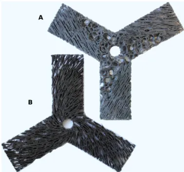
The new movement we create and study here is torsion. We have tested two configurations in order to achieve this as shown in Fig. 8. The first one (A) is a combination of stiff transverse isotropic with a direction of 0,120 and 240° respectively for each arm with 30% of density and a softer
Fig. 7: The Tripod Robot is composed of a soft silicone piece actuated by three servomotors, the robot can achieve a nearly infinite number of shape configurations.
isotropic foam of 15% of density. The second case (B) is completely transverse with a density of 15% but with a direction varying in a way to create spiral with its fibers. We can see in Fig. 9 a comparison of both meso-structured sheets with the silicone as a reference with a total angle of actuation of +/-49 degree.
For both cases, a torsion is created with a reasonable total angle of rotation. We can certainly achieve, with optimization, even more torsion.
Fig. 8: 3D-printed flexible sheets made with IceSL.
Fig. 9: Comparison of 3 tripods : one made of silicone and totally isotropic (left) and 2 others corresponding respectively to the case A (middle) and B (right) already presented.
To simulate this flexible structure, we have a tetrahedral mesh of 2684 elements. We study the two cases that are illustrated in Fig. 8.
For case A, we have mixed isotropic and anisotropic re-gions. We thus select the groups of tetrahedra and put them either the homogenized mechanical parameters of the isotropic case corresponding for this density, either the transverse for which we also add the directions previously presented.
For the case B, all the elements of the model are in transverse case and have their own corresponding direction.
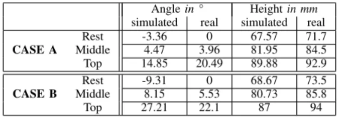
In Table I we can see a comparison between the reals and simulated tripods. We saved the data for 3 positions : rest where the robot actuation begin, middle is rest position with 19°of actuation for each motors, and finally top position where we actuate again all motors of 19°, resulting in a total actuation range of 38°. The measure is performed by an Optitrack system. We can then compare both real and simulated movement. Here we only track the center of the soft sheet giving us its height and torsion evolution.
V. DISCUSSION
Overall the results demonstrate that the global behavior of the robot can be captured by the modeling process. The direc-tion of modirec-tions are correct and the kinematics is reproduced. In the displacements both in rotation and translation, the order of magnitudes are coherent.
It means that we could envision to use this modeling process – that do not require any fabrication – and simulate the robot during the design phase, so that the designer have a better understanding of the behavior or to apply optimization algorithms.
However, important errors in position remain. It can be explained by the successive approximations made in the method. The homogenization is inherently a simplification of the behavior of the stochastic foam. In particular self-collisions
inside the structure due to large displacement are not taken into account.
The printing is not perfect. For case A, for instance, in the FEM model, there is no transition between fully isotropic and fully anisotropic regions. In practice the transition is graded. Oozing during printing is also an issue. In the simulation the robot is supposed to create more foam deformation on the rest position (negative rotation), but in practice the movement is limited by burrs in the foam.
Angle in ° Height in mm simulated real simulated real CASE A Rest -3.36 0 67.57 71.7 Middle 4.47 3.96 81.95 84.5 Top 14.85 20.49 89.88 92.9 CASE B Rest -9.31 0 68.67 73.5 Middle 8.15 5.53 80.73 85.8 Top 27.21 22.1 87 94
TABLE I: Comparison between simulated tripod and real one for 3 positions. We measure only the Height and Angle of the tip of the tripod
VI. CONCLUSIONS AND PERSPECTIVES This paper opens up a new way of designing soft robots with anisotropic behaviors by using 3D printed stochastic foams.
We present a modeling method based on numerical homog-enization and numerical integration with the Finite Element Method to predict the behaviour of soft robot made of meso-structured material. This method allows to test different de-signs before actually making the robot in reality since the geometry and the field of anisotropy can be varied in the simulation.
In this paper we demonstrate the change of kinematics and evaluate the model on a relatively simple parallel soft robot. It illustrates the potential of this new method. There are many venues for improving the model as mentioned in the discussion. In the future we can think of ways to optimize the design of more complex soft robots and really control the resulting properties. To reach this objective and find the best design for achieving given tasks, the simulation tool could be used to compute a cost function for shape optimization using genetic algorithms.
This and investigating the placement of actuators and sen-sors inside the printed foam is a direction for future works.
REFERENCES
[1] Katia Bertoldi et al. “Flexible mechanical metamateri-als”. In: Nat. Rev. Mater. 2 (2017).
[2] Ahmad Rafsanjani, Katia Bertoldi, and Andr´e R. Stu-dart. “Programming soft robots with flexible mechanical metamaterials”. In: Sci. Robot. 4.29 (2019).
[3] Jakob A Faber, Andres F Arrieta, and Andr´e R Studart. “Bioinspired spring origami”. In: Science 359.6382 (2018), pp. 1386–1391.
[4] Tian Chen et al. “Harnessing bistability for di-rectional propulsion of soft, untethered robots”. In: Proceedings of the National Academy of Sciences 115.22 (2018), pp. 5698–5702.
[5] Melanie F Simons et al. “Tiled Auxetic Cylinders for Soft Robots”. In: 2019 RoboSoft. IEEE. 2019, pp. 62– 67.
[6] Christian Schumacher et al. “Microstructures to con-trol elasticity in 3D printing”. In: ACM Trans. Graph. (2015).
[7] Julian Panetta et al. “Elastic textures for additive fab-rication”. In: ACM Trans. Graph. 34.4 (2015), 135:1– 135:12.
[8] Bo Zhu et al. “Two-scale topology optimization with microstructures”. In: ACM Transactions on Graphics (TOG) 36.5 (2017), p. 164.
[9] Jon`as Martınez, J´er´emie Dumas, and Sylvain Lefebvre. “Procedural voronoi foams for additive manufacturing”. In: ACM Transactions on Graphics (TOG) 35.4 (2016), p. 44.
[10] Jon`as Mart´ınez et al. “Orthotropic k-nearest foams for additive manufacturing”. In: ACM Trans. Graph. 36.4 (2017), pp. 1–12.
[11] Jon`as Martınez et al. “Polyhedral Voronoi diagrams for additive manufacturing”. In: ACM Transactions on Graphics (TOG) 37.4 (2018), p. 129.
[12] Tanaka Mori and K Tanaka. “Average stress in matrix and average elastic energy of materials with misfitting inclusions”. In: Acta metallurgica 21.5 (1973), pp. 571– 574.
[13] Sia Nemat-Nasser, M Lori, and SK Datta. “Microme-chanics: overall properties of heterogeneous materials”. In: Journal of Applied Mechanics 63 (1996), p. 561. [14] JC Michel, H Moulinec, and P Suquet. “A
computa-tional scheme for linear and non-linear composites with arbitrary phase contrast”. In: Int. J. Numer. Meth. Eng. 52.1-2 (2001), pp. 139–160.
[15] Eulalie Coevoet et al. “Software toolkit for mod-eling, simulation, and control of soft robots”. In: Advanced Robotics 31.22 (2017), pp. 1208–1224. [16] O. Goury and C. Duriez. “Fast, Generic, and Reliable
Control and Simulation of Soft Robots Using Model Order Reduction”. In: IEEE Transactions on Robotics 34.6 (Dec. 2018), pp. 1565–1576.
[17] Sandrine Germain. “On Inverse Form Finding for Anisotropic Materials in the Logarithmic Strain Space”. PhD thesis. July 2013.