HAL Id: hal-00950533
https://hal.inria.fr/hal-00950533
Submitted on 21 Feb 2014
HAL is a multi-disciplinary open access
archive for the deposit and dissemination of
sci-entific research documents, whether they are
pub-lished or not. The documents may come from
teaching and research institutions in France or
abroad, or from public or private research centers.
L’archive ouverte pluridisciplinaire HAL, est
destinée au dépôt et à la diffusion de documents
scientifiques de niveau recherche, publiés ou non,
émanant des établissements d’enseignement et de
recherche français ou étrangers, des laboratoires
publics ou privés.
Application Architecture Adequacy through an FFT
case study
Emilien Kofman, Jean-Vivien Millo, Robert de Simone
To cite this version:
Emilien Kofman, Jean-Vivien Millo, Robert de Simone. Application Architecture Adequacy through
an FFT case study. JRWRTC2013 - 7th Junior Researcher Workshop on Real-Time Computing,
Sebastian Altmeyer, Oct 2013, Sophia Antipolis, France. �hal-00950533�
Application Architecture Adequacy
through an FFT case study
Emilien Kofman
12Jean-Vivien Millo
1Robert de Simone
1 1INRIA Sophia-Antipolis, Aoste team (INRIA/I3S/CNRS/UNS), 06560, Sophia-Antipolis, France
2
Univ. Nice Sophia Antipolis, CNRS, LEAT, UMR 7248, 06900 Sophia-Antipolis, France {emilien.kofman, jean-vivien.millo, robert.de simone}@inria.fr
ABSTRACT
Application Architecture Adequacy (AAA) aims at tuning an application to a given hardware architecture. However it is still a difficult and error prone activity. As like as in Hard-ware/Software co-design, it requires a model of both the ap-plication and the architecture. With the new highly-parallel architectures, AAA should also allow a fast exploration of different software mapping granularity in order to leverage better the hardware resources without sacrificing too much productivity. The main contribution of this paper is to ex-tract from a case study a methodology based on dataflow modeling to make the software both faster to develop and suited to the target. Then we show how this methodology can solve some of these issues.
Keywords
Application Architecture Adequacy (AAA), Fast Fourier Trans-form, Hardware/Software co-design, Massively Parallel Pro-cessor Array (MPPA), parallel computing
1.
INTRODUCTION
This article identifies through a case study how to make the maximum use of the heterogeneous parallelism of the upcoming architectures. The example we picked is the well known FFT algorithm. It is often taken as a benchmark utility but one should keep in mind that this is almost al-ways a building block of larger software systems, and not a standalone application. Thus it is important to study its potential parallelism when running within the regular con-ditions. Moreover, the chip-level parallelism has a growing interest because it allows a large and scalable parallelism. It is now possible to aggregate many cores on the same chip but at some point the bus medium for data transfers be-comes the bottelneck because communication is serialized, hence the need for new communication media. This prob-lem can be solved using network on chips (NoC) which allow parallel communications. However it also raises much more complexity for the programmer.
It is possible to adapt an implementation to a given ar-chitecture although this work often requires many modifica-tions and is thus very time consuming and error prone. On contrary, given an implementation it is difficult to pick an ar-chitecture which would improve it (either for performance, energy consumption, temperature, cost). The reasons are that there exist only few tools for fast architecture design space exploration (such as [4, 7] based on systemC) and they often require expertise. Moreover the implementation
sometimes already assumes hardware specific features thus the need for a new representation.
2.
CASE STUDY
In order to identify which representation would fit we picked a DSP algorithm and tried to adapt it to a given system, while keeping in mind which choices are related to specificities of the given hardware system.
2.1
Hardware architecture
Very different, and heterogeneous hardware architectures exist. General purpose GPU offer a very massive fine-grain parallelism while multi-core CPUs offer coarse-grain paral-lelism. Many-core architectures fall in the middle. The ex-perimental platform is the Kalray Massively Parallel Pro-cessor Array (MPPA-256). It has 16 clusters of 16 VLIW cores, which yields a total of 256 VLIW cores. The clus-ters are connected through a network-on-chip which is ac-cessible through a message passing interface. The cores inside a cluster are connected through a bus and share a 2MB memory, then the parallelism is leveraged thanks to openMP. Additional cores are available for input/output purposes (PCIe/Ethernet/GPIO/Interconnect). Thus one Kalray MPPA-256 machine offers three levels of parallelism: • The compiler bundles instructions for VLIW cores and
thus provides an instruction level parallelism.
• A shared-memory intra-cluster parallelism using openMP or POSIX threads.
• A message-passing inter-cluster parallelism using a spe-cific message passing interface.
2.2
FFT implementation
A from-scratch iterative Cooley-Tukey decimation in fre-quency implementation allows to understand better the data dependencies in this algorithm. Decimation in frequency was preferred instead of decimation in time because it splits the dataset in half at each stage instead of splitting even/odd sample indices. It is thus easier to experiment with, espe-cially on a distributed memory architecture. However, a DMA-assisted transfer could efficiently split even/odd sam-ples.
The FFT implementation often comes with different steps (normalizing, FFT, unscrambling). The FFT Step requires multiple stages which are a set of mutiply-add operations named radix. For instance, a 213
samples radix2 FFT has 13 stages of 212
radix2 operations. In this paper, Step is disambiguated from Stage which is part of the FFT Step.
The radix operation is the building block of the FFT al-gorithms. Optimized routines exist for radix2 to radix16 (including radix3, radix5,...). It is sometimes called a but-terfly operation due to its datapath representation. It is made of multiply-add operations and requires constant co-efficients named twiddle factors. When done in-place (one buffer for both input and output), the FFT algorithm out-puts results in bit-reversed order. Thus, the samples need to be sorted, this is the unscrambling step. The resulting sam-ples often need a normalization factor which can be applied either at the end or along the FFT stages. In order to check the implementation performance, the pseudo-throughput is defined: let N be the number of samples:
throughput(Gf lops) =5.N.log2(N )
time(ns) (1) An inplace transform is implemented and the twiddle fac-tors are pre-computed. The bit-reversing steps and normal-izing steps were implemented for functional testing but are not taken into account in this study because depending on the whole application, they may not be necessary. Moreover the bit-reversing is sometimes hardware-accelerated (some DSP are capable of bit-reversed addressing). The algorithm shows that at each stage of the FFT, all the radix opera-tions could run in parallel (provided sufficient computation units). Then, synchronization is needed at each stage and the stages could be pipelined (provided sufficient memory). This is the ideal, maximum parallelism of the application which is reached for example in hardware implementations or with GP-GPU implementations [9].
One should keep in mind that most of the signal processing applications will use the FFT on a dataset with a power-of-two number of elements, and within a given range (usually not larger than 212
). Moreover, applications will very-likely run batches of FFT, and not a single one (for instance for image processing purposes).
Apart from GPU implementations, few work exist on the highly parallel implementation efficiency of FFT on distributed memory architectures, and they either conclude that the se-quential implementation runs faster ([3]) or that the parallel implementation runs faster for a very large (non-realistic) dataset of more than 212
samples. Other parallel implemen-tations study only multidimensional FFTs, which fall in the scope of ”batched FFTs”, and thus gives better results than one-dimensional FFT on reasonable datasets because they allow a simpler data-parallelism. For instance when running a 2D-FFT, one can run first 1D-FFT on each row (and they are independant), then run 1D-FFT on each column.
Although this study focuses on parallel implementations, sequential efficiency of the algorithm is of course important. radix2, radix4 and radix8 versions of the algorithm have been implemented and radix4 and radix8 clearly outper-forms radix2 (by a factor of 3.3x on x86 CPU). Mixed-radix has not been implemented.
2.3
Results
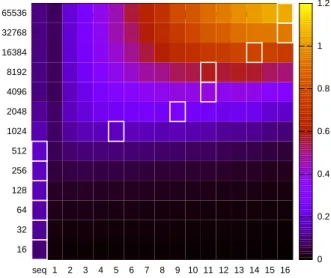
The implementation first focuses on shared memory paral-lelism achieved with openMP (Figure 1 on x86 and Figure 2 on MPPA), then evaluates distributed-memory parallelism. The provided tools allow to compile both for Kalray’s ar-chitecture and for the Host’s arar-chitecture (which is an Intel i7-3820 CPU with 8 cores). The scale on the right gives the pseudo throughput (equation 1). White edges identify
the number of threads which allows highest throughput for given FFT size. The sequential column shows performance when openMP pragmas are ignored, which differs from the 1-thread column (openMP pragma are not ignored but the number of threads is restricted to 1).
16 32 64 128 256 512 1024 2048 4096 8192 16384 32768 65536 seq 1 2 3 4 5 6 7 8 9 10 11 12 13 14 15 16 "<awk '{$1=\"\"}1' colormap | sed '1 d'" matrix
0 1 2 3 4 5 6 7 8 9 10
Figure 1: FFT size over number of threads on host
16 32 64 128 256 512 1024 2048 4096 8192 16384 32768 65536 seq 1 2 3 4 5 6 7 8 9 10 11 12 13 14 15 16 "<awk '{$1=\"\"}1' colormap | sed '1 d'" matrix
0 0.2 0.4 0.6 0.8 1 1.2
Figure 2: Evaluation on one 16-cores cluster As you can see, there is significant speedup in both cases but there are also few differences. The absolute performance of the CPU is higher than on one MPPA cluster. The most interesting result is probably that the parallel implemen-tation outperforms the sequential implemenimplemen-tation even for small sizes on CPU, but only for ”large” sizes (more than 210
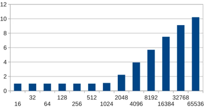
samples) on one cluster. This may be due either to dif-ferent openMP implementations or to the fact that VLIW cores already perfom the radix steps in fewer operations, thus reducing the computation time over sync time factor. Figure 3 gives the maximum speedup performance results. This shows a 11x speedup for large FFT sizes. Although we admitted that such large datasets are not often used, this
16 32 64 128 256 512 1024 2048 4096 8192 16384 32768 65536 0 2 4 6 8 10 12
Figure 3: Maximum speedup on one MPPA cluster
gives a clear idea of the reachable speedup performance for batched FFTs or multidimensional FFTs because it is pos-sible to run only a subset of the 216
FFT stages such that it computes multidimensional FFTs of smaller sizes (recip-rocally, a large FFT can be computed combining the results from smaller FFTs). Given these results, it is probably wiser to run batches of FFTs to leverage best this architecture. This means this architecture is not very well suited to fine grain parallelism but can achieve massive coarse grain paral-lelism. The figures shows that provided low communication overhead it would probably outperform CPU when running batches of FFTs on 16 clusters.
This experiment rises two problems: The application and the architecture needs to be described in such a way that it is easy to allocate resources differently given the same (vali-dated) implementation. The description of the architecture needs to be precise enough in order to formally decide the best suited parallelism granularity for a given hardware ar-chitecture.
3.
MODELING METHODOLOGY
Deciding which amount of parallelism should be auto-mated is now an actively studied topic. The related works in this area yield at least two main methodologies.
Some methods would take legacy code and compile it through a front-end to an intermediate (possibly hardware-independent) representation [2]. Then identify parallelism in this representation with a custom tool and apply back-end transformations according to the given architecture. This source to source compiling allows to identify fine-grained parallelism (e.g Instruction Level Parallelism) which is for instance necessary when compiling code for a VLIW archi-tecture but extracting coarse grain and pipeline parallelism is not easy.
Another way to tackle this problem is to express applica-tions in a dataflow-representation (either with a text-based or graphical language) in order to ease the identification of parallelism, then compile it to a given architecture. Given the appearence of specific languages for specific architectures (e.g. Open Computing Language for GPUs) it is reasonable to think that a new representation is needed for signal pro-cessing and multimedia applications.
3.1
Motivations
Many attempts exist in this area ([1, 5]) but for instance in the case of StreamIt[5], the description of the
architec-ture is limited to sparse information (number of threads, size of caches), and no model of the architecture is provided in order to help the allocation mechanism. This can result in under-performing implementations. For instance using sock-ets for inter-process communication, either when processes are located on the same machine or on another machine on the network provides homogeneity to the whole compilation process, but using the shared memory would be more effi-cient. Thus compiling a streamIt application for another ar-chitecture involves changing the compiler’s behavior which is a tough task. GUI-programming tools also exist when it comes to mapping dataflow applications onto hardware. They allow very comfortable learning and fast prototyping but they do not compete with hand-written applications. Moreover they are sometimes bound to specific hardware.
3.2
Dataflow graph representation
Synchronous Data Flow ([6], SDF) is a dataflow process network used to express logical parallelism of data flow cations. A functionnally correct representation of an appli-cation within SDF allows formal checking for deadlock, star-vation, conflict. Moreover it is now admitted that it eases analysis of the buffer size over throughput compromise and thus allows further optimisation for instance through static scheduling [8].
An SDF is a graph structure in which every vertex has a type. The graph has a set of agents N , a set of places P and a set of arcs. The edges of an SDF are directed, they are hence called arcs. An arc cannot connect two vertices of the same type. An arc in an SDF has a width expressed with a non-zero integer that represents the number of tokens travelling simultaneously on it. The places hold tokens. Each place has exactly one incoming and one outgoing arc.
This representation makes no assumption on the archi-tecture (buffer sizes, execution speed). In the scope of this article, an SDF models an application where the agents rep-resent the different filters (or actors) that can be performed concurrently in the application. The places represent a loca-tion in memory. The arcs represent the flows of data (data dependencies). The presence of a token in a place represents the availability of a data element in the memory. An agent without incoming (outgoing) arc represents a global input (resp. output) of the application. The arcs does not neces-sarily describe an access in memory or a channel of commu-nication but a flow of data between agents. The nature of the link will come with the description of the architecture.
It is then possible to give a (very fine grain) SDF graph of the FFT algorithm which is actually very close to the well known butterfly diagrams, which exposes the maximum par-allelism. Expressing the same algorithm serially obfuscates the data dependencies. Because of the very repetitive pat-terns it would be easier to represent the application with a language or a set of classes (as like as streamIt or FastFlow) and not graphically.
3.3
Morphing and mapping
Given a precise description of the architecture, this SDF representation can be morphed to the correct parallelism level, then mapped to an hardware architecture. For in-stance if the FFT has to be implemented on GPU, the very fine grain representation could be fine. However if it has to be implemented on CPU, it would be very time consuming to synchronize that much threads (assuming one agent is
mapped to one thread) thus it is not the correct represen-tation: on contrary the Figure 1 shows that it is essential to limit the number of threads accordingly to the number of cores.
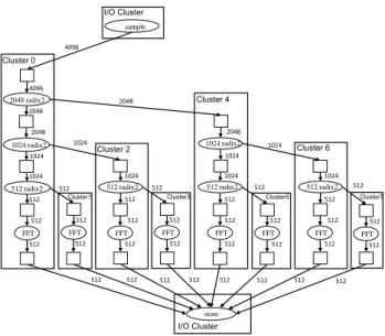
Indeed, a precise description of the architecture and its communication media should allow to split and merge agents depending on communication throughput/latency, DMA en-gines, routing in the case of network on chips and depend-ing on the computation elements (size of their cache and local memories, co-processors, VLIW or SIMD features, ...). Then, the actual data moves can easily be identified. We in-troduce the following morphed and mapped FFT represen-tation (Figure 4). The assumed hardware in this example is an heterogeneous shared/distributed memory architecture as like as the Kalray MPPA-256. Two places which are in the same cluster can benefit from shared memory (reduces communication time and memory consumption compared to a FIFO). Only the edges from one cluster to a different clus-ter require message passing. These clusclus-ters have a DMA thus the message passing could be asynchronous.
sample 4096 4096 2048 radix2 2048 2048 1024 radix2 1024 1024 512 radix2 512 512 FFT 512 store 2048 1024 radix2 1024 1024 512 radix2 512 512 FFT 512 1024 512 radix2 512 512 FFT 512 1024 512 radix2 512 512 FFT 512 512 FFT 512 512 FFT 512 512 FFT 512 512 FFT 512 2048 512 512 512 512 512 512 512 512 1024 512 512 512 512 1024 I/O Cluster I/O Cluster Cluster 0
Cluster1 Cluster3 Cluster5 Cluster7
Cluster 2
Cluster 4
Cluster 6
Figure 4: A 4096-samples FFT algorithm repre-sented with a dataflow, then morphed to fit an archi-tecture composed of8 distributed memory clusters. Further investigation on a 4096 samples FFT shows that assuming no shared memory parallelism, positive speedup is obtained when splitting the first stage, but not when split-ting the second stage. However combining openMP and message passing in this manner does not provide positive speedup.
4.
FUTURE WORKS
The tough task of the morphing and mapping steps is to decide the representation level to allow a correct exploration for a performant implementation. Indeed the architecture has to be described but the abstraction level is not yet iden-tified. Assuming the heterogeneities (for instance between a regular CPU, a processor array, and a GPU), it is clear that at least a high level representation (UML/SysML) of the hardware is needed and not only sparse information. Different level of complexity exist: non-functionnal UML,
systemC-TLM or CABA (Cycle Accurate Bit Accurate), ISS, complete IP-XACT descriptions. An other obstacle to this exploration is that it is sometimes hard to obtain precise information about the hardware, especially for specialized chips (GPUs, accelerators).
5.
CONCLUSIONS
The present paper explained through an example how software development of DSP and multimedia algorithms could improve in order to ease code reuse and validation on mutiple hardware targets. The dataflow representation, and especially the SDF representation of applications [8] comes naturally as a suitable candidate for hardware-independent and optimisation capable representation. However picking a hardware representation for fast design space exploration and for performant implementation is still complex.
6.
REFERENCES
[1] M. Aldinucci, M. Danelutto, P. Kilpatrick, and M. Torquati. Fastflow: high-level and efficient streaming on multi-core. In S. Pllana and F. Xhafa, editors, Programming Multi-core and Many-core Computing Systems, Parallel and Distributed Computing, chapter 13. Wiley, Jan. 2013. [2] M. Amini, B. Creusillet, S. Even, R. Keryell,
O. Goubier, S. Guelton, J. O. McMahon, F.-X. Pasquier, G. P´ean, P. Villalon, et al. Par4all: From convex array regions to heterogeneous computing. In IMPACT 2012: Second International Workshop on Polyhedral Compilation Techniques HiPEAC 2012, 2012.
[3] M. Balducci, A. Choudary, and J. Hamaker.
Comparative analysis of fft algorithms in sequential and parallel form. In Mississippi State University
Conference on Digital Signal Processing, pages 5–16, 1996.
[4] L. Benini, D. Bertozzi, A. Bogliolo, F. Menichelli, and M. Olivieri. Mparm: Exploring the multi-processor soc design space with systemc. Journal of VLSI signal processing systems for signal, image and video technology, 41(2):169–182, 2005.
[5] M. I. Gordon. Compiler Techniques for Scalable Performance of Stream Programs on Multicore Architectures. PhD thesis, Massachusetts Institute of Technology, 2010.
[6] E. A. Lee and D. G. Messerschmitt. Synchronous data flow. Proceeding of the IEEE, 75(9):1235–1245, 1987. [7] LIP6. The soclib project : An integrated
system-on-chip modelling and simulation platform. http://www.soclib.fr/, 2003.
[8] J.-V. Millo and R. De Simone. Periodic scheduling of marked graphs using balanced binary words. Theoretical Computer Science, 2012.
[9] V. Volkov and B. Kazian. Fitting fft onto the g80 architecture. University of California, Berkeley, 40, 2008.