HAL Id: hal-02308208
https://hal-enac.archives-ouvertes.fr/hal-02308208
Submitted on 8 Oct 2019
HAL is a multi-disciplinary open access
archive for the deposit and dissemination of
sci-entific research documents, whether they are
pub-lished or not. The documents may come from
teaching and research institutions in France or
L’archive ouverte pluridisciplinaire HAL, est
destinée au dépôt et à la diffusion de documents
scientifiques de niveau recherche, publiés ou non,
émanant des établissements d’enseignement et de
recherche français ou étrangers, des laboratoires
Aurélien Cabarbaye, Titouan Verdu, Fabien Garcia, Michel Gorraz, Alexandre
Bustico, Murat Bronz, Gautier Hattenberger
To cite this version:
Aurélien Cabarbaye, Titouan Verdu, Fabien Garcia, Michel Gorraz, Alexandre Bustico, et al.. Design
of a high performance MAV for atmospheric research. IMAV 2019, 11th International Micro Air
Vehicle Competition and Conference, Sep 2019, Madrid, Spain. �hal-02308208�
Design of a high performance MAV for atmospheric
research
Aur´elien Cabarbaye, Titouan Verdu, Fabien Garcia, Michel Gorraz, Alexandre Bustico, Murat Bronz, and Gautier Hattenberger
ENAC, Universit´e de Toulouse, France firstname.lastname@enac.fr
ABSTRACT
This article presents the design of a mini UAV dedicated to atmospheric research with tight op-erational constraints coming from the end-users, which are the meteorologists associated to the project. Several aspects are covered in addi-tion to the conceptual design of the frame it-self and its manufacturing process. This includes the innovative launching system based on water rocket, the design of a 5-hole probe for wind and turbulence measurements, the new version of the on-board autopilot and finally the evaluation of a long range communication system. Preliminary results are presented to conclude the paper.
1 INTRODUCTION
Unmanned Aerial Vehicles (UAV) are now commonly used for scientific research and especially in atmospheric re-search [1, 2] with a wide range of scale and mission. They have proved themselves to be cheaper and more agile than manned aircraft or balloons to probe the low-level atmo-spheric boundary layer. It is also important to be able to op-erate them in all sorts of weather conditions, including rain and strong winds [3]. However, flying a small UAVs at high speed, in harsh conditions and with a flight time as long as possible raises many technical challenges, especially to keep the overall system easy to operate.
One of the key measurement is the turbulence of the atmo-sphere which usually requires the use of 3D wind probes [4]. These type of sensors are already commercially available, like the µADC from Aeroprobe, but are pretty expensive and re-quires cumbersome electronic boards. It is also important to increase the sampling frequency with the speed of the aircraft in order to maintain a large usable bandwidth [5].
This article presents the design of a high performance small UAV designed for atmospheric turbulence measure-ments at high speed. After presenting the mission and the op-erational constraints in section 2, section 3 will describe the aircraft conceptual design and its innovative launching sys-tem, the next section will then focus on the on-board system integration and the design of a 3D wind probe. Finally pre-liminary flight and sensors tests will conclude the paper.
2 MISSION OVERVIEW AND CONSTRAINTS
The mission considered in this article is the measurement of the turbulence of the atmosphere with a small UAV. This is part of the NEPHELAE project, which involves atmospheric scientists as well as researchers in aerial robotics.
From the long experience of the authors in similar UAV operations [6, 7], it has been decided that a particular focus will be made on the take-off and landing procedures, as well as the capability of the plane to fly in strong wind conditions. The UAV should be able to fulfil the following require-ments:
• Lift a maximum of 800 grams of scientific payload in a roomy enough cargo bay.
• Cruise more than 2 hours to give the entire observation period coverage without having to land for recharging. • Cruise at an average altitude of 3000 m above sea level
where weather phenomena take place.
• Cruise at a speed of around 25 m/s which is fast enough to both counter the violent turbulences accompanying observed weather phenomena and to move from one measurement point to another in an acceptable time. • The whole, fully equipped, aircraft should not weight
more than 2.5kg to be easily transportable even in re-mote operating areas.
One of the main issue that is arising from these require-ments is coming from the rather high cruise flight speed which prevents the use of off-the shelves airframes that would not be able to fly as fast (or as long, if overpowered) as ex-pected, as it will be seen in section 3.
Figure 1 shows a typical location for operating UAVs without any proper ground infrastructure such as a runway. There is not even a flat space for belly landing. The UAV sys-tem must therefore presents VSTOL capability, which will be detailed in sections 3.2 and 3.3.
3 AIRFRAME DESIGN
Aircraft conception is an iterative process that covers the conceptual design, the definition of the launching and recov-ering systems and the manufacturing choices.
Figure 1: Base camp for operations of MAV in harsh environ-ment.
3.1 Aircraft conceptual design
The conceptual design consist in optimizing the aircraft characteristics assessing its performances on a typical mis-sion.
The basic architecture of the aircraft is predefined: • A pusher configuration is adopted in order not to
inter-fere with the sensors accommodated in the nose of the aircraft (cf. section 4).
• An electric power-plant is selected for its simplicity in operation. Sufficient autonomy can be achieved when combined with lithium-ion batteries. The battery is a homemade pack of 18650 type cells of 3500mAh ca-pacity each.
• The aircraft is likely to withstood high vertical wind gradients. Therefore, a flying wing configuration is adopted in order to reduce turbulence by minimiz-ing the longitudinal distance between the aerodynamic center and the lifting surfaces.
• The electric systems in the fuselage are air cooled by a flow entering through a particle separator located in the nose.
One of the design case mission considered is presented in Figure 2 which is a vertical profile up to the top of the cloud formation.
Main optimization parameters are the chord and the span of the wing, the motor and the propeller. The software used (GENCAB) for this study is based on genetic algorithms, dif-ferential evolution and non-linear simplex (Nelder Mead al-gorithm). This hybridisation of global and local techniques makes the convergence of the overall algorithm quicker and also increases the robustness of the tool over a variety of prob-lems, and in particular problems involving alphanumeric pa-rameters. The optimization process leads to a high wing load-ing to reduce the zero lift drag produced by the wload-ing wetted
Figure 2: UAV typical mission.
area. High wing loading presents the other advantage to be less turbulence sensitive. However its drawback is a higher stall speed which has been limited to 13 m/s for take-off and landing operations.
Moreover, the propulsion system maximum power have been chosen much higher than what is required in cruise in order to reduce the climb time to 3000m.
3.2 Launching systems
The relatively high stall speed imposes the use of a launching systems since a whole prototype has been lost dur-ing a hand launched test.
Several existing options have been considered:
• Cataplut launching seems to be the most popular solu-tion. Tests have been performed with two off the selves systems. It results that either they do not transmit suf-ficient energy to the aircraft (SKYWALKERRC) or the acceleration is much too high (Gatewing) for the struc-ture, the autopilot and the payload. Figure 3 shows the position of a dummy UAV along the time obtained dur-ing a test. The final velocity is about 17.5m.s−1which
Figure 3: catapult launching performance
would be sufficient, but the acceleration is around 9.8g which is unacceptable. In addition, the maximum ve-locity is reached at less than one meter high which is
dangerous for operators and does not provide sufficient clearance.
• Winch launching using a bungee and placing the plane on a ramp at the beginning achieves good repeatabil-ity. It presents much lower accelerations, however this solution requires planes with rather low stall speed so that the plane doesn’t touch the ground after leaving the ramp. If it is not the case, a longer ramp can be used at the expense of a possible uncontrolled yaw moment due to the friction of the wing on the ramp.
• Car (manned or RC) top launching do not present the latter defect but requires an even longer clear flat area to be operated.
• Trebuchet launching or multicopter lifting are more un-usual solutions because they require relatively bulky fa-cilities.
• Several UAVs are rocket launched following the idea of the Zero-length launch of manned aircraft developed in the 1950’s. The main issues with this method is the fire hazard represented by the solid fuel rocket.
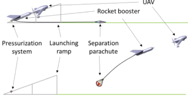
Therefore, a specific takeoff system based on a water rocket has been designed. Its main advantages are: limited acceleration, high height clearance, very high reachable air-speed, very compact facilities, only little hazard compare to the solutions previously presented. In addition, the launch pad consists in a tube inserted in the water rocket that guide it at the very beginning of the launch and reduce the waste of water acting like a piston. The maximal acceleration can be limited by reducing the nozzle diameter, while the internal volume of the water rocket is computed in order to store the required amount of energy. The acceleration has been limited here to 4g. The UAV is released at 15 m/s and 8 m high with an initial pressure of only 9 bars. The acceleration is thus much more gentle than with a catapult as it can be noticed in Figure 4.
However, its integration is more restrictive than for a clas-sical Jet-Assisted Take-Off (JATO) system that is jettisoned in flight like a drop tank. As water rocket has indeed a much lower specific energy than solid fuel rocket, it cannot be fixed underneath the aircraft and must be placed at the rear of the drone like the first stage of a rocket. In this position, the CG is very far back. An additional lifting surface must therefore be added at the very back of the water rocket to restore the natural longitudinal stability. The additional lifting surface area is computed in order to move the aerodynamic center behind the center of gravity of the set with a static margin of 5% of the UAV aerodynamic chord. The UAV and the rocket are connected thanks to a cone shape coupler made of a male plug mounted on the motor shaft and a female plug put on top of the rocket. A parachute is added to the assembly through a cable ensuring the separation of the two components on time.
Figure 4: Water rocket performances
The parachute is laid on the floor beyond the drone and is naturally inflated when the UAV passes over it. A diagram illustrating the operation principle of water rocket launching is shown in Figure 5.
Figure 5: Water rocket launch phases.
3.3 Recovering systems
Several solutions can be implemented to obtain a short or vertical landing. The most popular solution consists in ac-commodating a ballistic parachute in the airframe. Despite the fact that very reliable systems are available on the market for the considered aircraft size, the additional weight is too high not to be detrimental.
Arresting hook is another solution but it still requires a piece of runway and constitute another overweight.
Therefore, a vertical arresting net has been selected since it can be used on almost every cleared ground and do not need any additional on-board system.
3.4 Manufacturing process
The manufacturing process is custom to deal with the un-usual constraints of the chosen UAV operation mode. In ad-dition, the manufacturing must be easy, fast, low cost in order to produce the whole fleet on time, on cost and with the
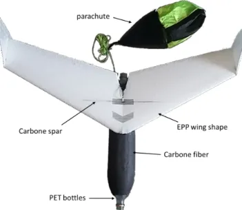
re-quired quality. To do so, several solutions have been adopted as shown in Figure 6.
Figure 6: UAV construction.
The high aspect ratio combined with the high wing load-ing and the high expected turbulence impose the use of a spanwise carbon spar. In order to gain weight, the back half of the wing is built from an extruded polystyrene foam block with a hot wire CNC. This material has a high stiffness suit-able for the sharp trailing edge. The front half is built with the same tool but from a block of expended polypropylene which offers a very good shape memory that is of great interest when the UAV impacts the arresting net. The joint between the two parts is made of a mixture of resin and glass micro-sphere. The obtained wing is covered with a high-density polyethy-lene film that protects it against abrasion and improves its polishing.
The planned number of UAVs is too low to justify the purchase of fuselage moulds. Therefore an innovative man-ufacturing process has been developed. The external skin of the fuselage is 3D printed in PET. The PET is chosen because of its very good inter-layer cohesion and its very low wrap-ping despite its higher density compared with ABS. However, the fuselage is built with the minimum possible thickness that ensures good printing result. The strength of the fuselage is obtained by laying carbon fibers on the inside surface of the printed part. The resulting fuselage presents the strength of a carbon molded part at the cost of a 3D printed part.
The water rocket is built by splicing two 2L soda bottle back to back. the maximum tolerable pressure is around the expected 9 bars. Therefore, a carbon fiber fabric is wrapped around the bottles assembly. Test have been performed up to 12 bars without showing any weakness. The wing is made of a carbon spar reinforced extruded polypropylene foam shape to withstood hard landings. The general layout of the water rocket booster is shown in Figure 7.
4 SYSTEM INTEGRATION
4.1 Autopilot
The open-source autopilot system used to equipped the UAVs is called Paparazzi[8]. The previous hardware boards
Figure 7: Rocket booster construction.
used during past project was reaching end-of-life since some components were declared obsolete by the manufactures, so it was decided the design a new version.
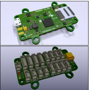
The general guidelines were to keep the board small, eventually with the same footprint than the previous gener-ation for easier upgrade, improve the connectivity to support more sensors and use latest available integrated components such as MCU and IMU. The main characteristics of this new board, named Tawaki, are listed in Table 1.
MCU STM32F7
IMU ICM20600 (accel, gyro) + LIS3MDL (mag)
Baro BMP3
Serial 3 UARTS, I2C (5V + 3.3V), SPI Servo 8 PWM/DShot output (+ ESC telemetry)
RC 2 inputs: PPM, SBUS, Spektrum AUX 8 multi purpose auxiliary pins
(ADC, timers, UART, flow control, GPIO, ...) Logger SD card slot
USB DFU flash, mass storage, serial over USB Power 6V to 17V input (2-4S LiPo)
3.3V and 5V, 4A output Weight 12 grams
Table 1: General characteristics for the Tawaki autopilot board.
The Figure 8 shows the top and bottom 3D view of the final design of the Tawaki autopilot. A first prototype have already been assembled and successfully tested so far. 4.2 Communication system
The communication system on this UAV needs to provide at least a 10 km range and accommodate for several aircraft.
Figure 8: 3D view of the final design of the Tawaki autopilot
As the 2.4GHz XBee modems used in previous projects were a bit too short in range, the P2400 from Microhard has been selected in place. Its main characteristics are shown in Ta-ble 2. It must be noted that two types of Lora modems pro-viding long range communication have been tested but the throughput of theses modems was two low to be usable for a UAV command and control link.
Frequency band 2400↔ 2483.5MHz Spreading method Frequency hopping
Link to autopilot UART or computer up to 230.4 kbps
Link Rate 19.2 to 345 kbps Emitted power up to 1W Power consumption TX peak 6.6W
Size 26.5x33x3.5mm
Weight 5g
Table 2: General characteristics for the P2400 modem. In order to estimate the communication range, a modem has been installed on board a UAV flying in circles at 150 m altitude while a car was driving away with another modem attached to a computer running a test program. To the day of writing this article, tests have been done with a wireless rate of 172.8 kbps resulting in a maximum range of 4.3km. This range is not sufficient for the planned mission, never-theless the sensitivity of the modem (and hence its maximum communication range) increases when one configures a lower wireless rate allowing for a range increase. Through simple computation with the Friis free-space transmission formula, the feasible range have been evaluated for a 55 kbps wireless rate to be around 7.7 km. Furthermore, we plan to use a direc-tive antenna which would give us a further boost in range up
to 14 km which should provide enough range even counting the attenuation due to clouds.
4.3 Turbulence probe
In order to measure the turbulence of the atmosphere, a commonly used type of sensors are the multi-hole probes. Their primary usage are to measure the angle of attack and the sideslip angle, which doesn’t require a very high sampling frequency, around 10 Hz. However, the dynamic of the tur-bulence requires a larger bandwidth with a minimum of 100 Hz.
For this project, a new integrated probe using fast differ-ential pressure sensor is under development. The main char-acteristics are presented in Table 3.
MCU STM32F7
Differential pressure 3 x SDP31 Absolute pressure LPS33HW
IMU ICM20600 (accel, gyro) Logger SD card slot
Data UART, USB
Powering 5V
dimensions 22 mm, L 110 mm min Table 3: Main features of the 3D wind probe Since it integrates a micro-controller and a SD card di-rectly inside the probe, the recording and processing at high frequency can be done with minimum latency and indepen-dently of the main autopilot. A serial UART connection al-lows to forward the filtered and pre-processed data to autopi-lot, which will eventually forward the messages to the ground for real-time monitoring.
In addition to this, IMU data can be recorded for angle correction, or processed in real-time using attitude filter. The serial connection can also be used to receive external data such as GPS position, speed and heading for a better recon-struction of the local 3D wind field.
The Figure 9 shows the preliminary design of this new sensor. The expected sampling frequency is 500 Hz for the differential pressure and 50 Hz for the absolute pressure.
4.4 Other sensors
In addition to the 3D wind probe, other meteorological sensors can be embedded inside the plane:
• Temperature and humidity, mostly used to build verti-cal profiles of the atmosphere the same way weather balloons would do.
• Cloud sensor [9] used to determine some of the char-acteristics of the water droplets and the liquid water content (LWC) of the atmosphere.
• Radiation sensors used to measure the albedo. 5 FLIGHT TESTS AND EXPERIMENTAL RESULTS
5.1 Flight patterns simulations
In order to efficiently sample the clouds, dedicated flight patterns have been defined based on the feedback from the scientists that will post-process them.
Figure 10: The different parts of the cloud that will require a specific focus during the mission.
The result is a set of predefined adaptive shapes that al-lows focusing the acquisition on certain parts of the cloud such as the border, the base or the core as shown on Figure 10. The real-time feedback from the sensors reduces the required time to sample a particular region corresponding to the phys-ical process being studied, thus providing a better set of data to reconstruct the complete evolution of the cloud. The other benefit of this expert-based approach is that the computational load is limited compared to previous work on this topic [7] and can be performed in real-time by the on-board autopilot without heavy computations on the ground.
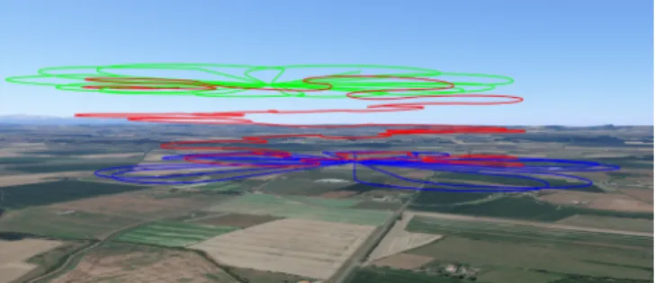
These strategy have been tested in simulations with real-istic aircraft and cloud models [10]. The Figure 11 is showing the flight tracks of three UAVs where two of them are measur-ing the vertical wind intensity at two different altitudes to es-timate the airflow inside the cloud, while the last one is cover-ing the border in 3D to estimate the volume. The turnarounds at the edge of the cloud are triggered based on the liquid water content estimation in real-time.
Figure 11: Simulation of 3 UAVs sampling 2 horizontal planes and the last one covering the outer 3D border.
5.2 Flight tests
Preliminary test flights have been performed with the op-timized planes. At the very beginning, the issues during take-off using conventional techniques, leading to a loss of the plane, conduct to the design of the rocket-based launching procedure.
The second second session of flight tests have revealed an issue linked to the structural vibrations of the aircraft. Those vibrations, which disturb the attitude (AHRS) estimation fil-ter, should be reduced prior to more flights. Two solutions have been implemented, which are a mechanical damping of the autopilot and a better filtering of the accelerometer data. 5.3 Five-Hole Probe Calibration (Prototype)
At the time of writing this draft paper, the final turbu-lence probe was not ready. In preparation for it, the calibra-tion procedure has been done with prototype electronics, and an off-the-shelf 5-hole probe from AeroProbe. The proto-type electronics consists of three differential pressure sensors (SDP31), an absolute pressure sensor, and STM32L4 micro-controller.
The calibration process has been done inside a low speed wind-tunnel facility, where the test section dimensions are 50cm by 50cm. The static ports on the probe are located at the very tip of the tube that has a spherical shape.
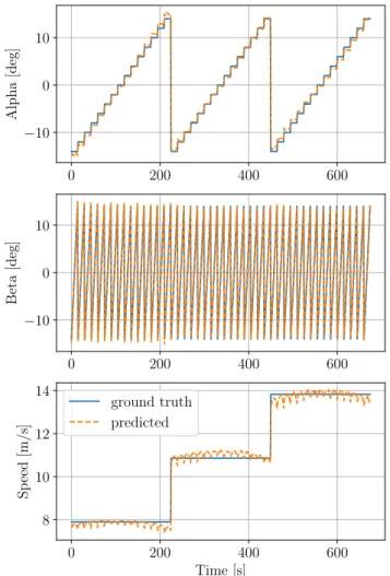
During the calibration process, it is important to keep the tip of the probe at the same location (fluid stream tube) in order to avoid possible uncertainties that may arise from nonuniform distribution of the speed. Therefore, a custom calibration bench has been designed and build that holds the tip of the probe in its center during the pitch and yaw move-ments. Figure 12 shows the calibration mechanism inside wind tunnel’s test section. The bench has been designed to move from -20 deg, up to +20 deg both in angle of attack and side slip axes. During calibration, first the airspeed is fixed, and then for each angle of attack, side slip angle has been changed. Once all angle of attack and side slip angles are covered, the wind tunnel speed has been changed and the process is repeated for different airspeed (8m/s, 11m/s, and 14m/s).
ap-Figure 12: Calibration bench located inside the test section of ENAC’s low speed wind-tunnel.
plied in order to estimate the angle of attack, side slip angle and the dynamic pressure by using the three on-board differ-ential pressure sensors as
αβ q = A PP12/P/P33 P3 + cc12 c3 ,
where A is a [3 × 3] coefficient matrix (obtained from the linear regression), and c1−3are the offset values.
As the angle of attack and side slip angles should be esti-mated independent of the airspeed, the linear regression fea-tures has been selected in a normalized way being P1/P3and
P2/P3. It can be understood that P3 is the differential
pres-sure sensor that is connected to the total prespres-sure and static pressure holes.
Figure 13 shows the result of the predicted angle of attack, side slip angle and the airspeed with respect to ground truth that comes from bench mechanism servo angles and wind-tunnel airspeed setpoint. The actual airspeed has been cal-culated by predicted dynamic pressure and the measured on-board absolute pressure and temperature values.
6 CONCLUSION AND ONGOING WORK
This paper has presented the overall design of a small UAV optimized for meteorological research, such as cloud and turbulence analysis. This includes the conception of the plane itself, taking into account the requirements of the atmo-sphere researchers, but also the adaptation of the manufac-turing process to make the structure easily reproducible and adaptable and the launching system adapted to the specific performances of the aircraft. In addition, a special attention to the system integration has led to the conception of an inte-grated 3D wind probe based on 5-hole measurements, a new
0 200 400 600 −10 0 10 Alpha [deg] 0 200 400 600 −10 0 10 Beta [deg] 0 200 400 600 Time [s] 8 10 12 14 Sp eed [m/s] ground truth predicted
Figure 13: Comparison of predicted versus ground truth val-ues of angle of attack, side-slip angle and the airspeed.
version of the main autopilot board and the integration of long range communication devices.
Future work will focus on the plane performances evalua-tion in real-flight, completing the final design of the 3D wind probe and manufacturing it in order to test it in flight.
ACKNOWLEDGMENTS
The NEPHELAE research project is founded by the French National Research Agency (ANR).
The authors would like to thank the researchers from the LAAS-CNRS and Meteo-France involved in this project.
REFERENCES
[1] Brandon M. Witte, Robert F. Singler, and Sean C. C. Bailey. Development of an unmanned aerial vehicle for the measurement of turbulence in the atmospheric boundary layer. Atmosphere, 8(10), 2017.
[2] Konrad B¨arfuss, Falk P¨atzold, Barbara Altst¨adter, En-dres Kathe, Stefan Nowak, Lutz Bretschneider, Ulf
Bestmann, and Astrid Lampert. New setup of the uas aladina for measuring boundary layer properties, atmo-spheric particles and solar radiation. Atmosphere, 9(1), 2018.
[3] Keri Allan. Within limits, how are drones being used to improve weather predictions? Meteorological Technol-ogy International, pages 38–42, April 2019.
[4] Radiance Calmer, Greg Roberts, Jana Preissler, Solene Derrien, and Colin O’Dowd. 3D Wind Vector Measure-ments using a 5-hole Probe with Remotely Piloted Air-craft. Atmospheric Measurement Techniques, 2018. [5] Dale A. Lawrence and Ben B. Balsley. High-resolution
atmospheric sensing of multiple atmospheric variables using the datahawk small airborne measurement sys-tem. Journal of Atmospheric and Oceanic Technology, 30(10):2352–2366, 2013.
[6] Gautier Hattenberger, Gr´egoire Cayez, and Greg Roberts. Flight tests for meteorological studies with MAV. In IMAV 2013, International Micro Air Vehi-cle Conference and Flight Competition, page pp xxxx, Toulouse, France, September 2013.
[7] Christophe Reymann, Alessandro Renzaglia, Fayc¸al Lamraoui, Murat Bronz, and Simon Lacroix. Adaptive sampling of cumulus clouds with UAVs. Autonomous Robots, 42(2):pp.491–512, February 2018.
[8] Gautier Hattenberger, Murat Bronz, and Michel Gor-raz. Using the Paparazzi UAV System for Scientific Re-search. In IMAV 2014, International Micro Air Vehicle Conference and Competition 2014, pages pp 247–252, Delft, Netherlands, August 2014.
[9] Gilles Harrison, Martin Airey, Graeme Marlton, Keri Nicoll, and Paul Williams. Volcanic ash detection. Meteorological Technology International, pages 54–56, September 2017.
[10] Titouan Verdu, Gautier Hattenberger, and Simon Lacroix. Flight patterns for clouds exploration with a fleet of uavs. In 2019 International Conference on Un-manned Aircraft Systems (ICUAS), Atlanta, 2019.