HAL Id: hal-02087328
https://hal.archives-ouvertes.fr/hal-02087328
Preprint submitted on 2 Apr 2019
HAL is a multi-disciplinary open access
archive for the deposit and dissemination of sci-entific research documents, whether they are pub-lished or not. The documents may come from
L’archive ouverte pluridisciplinaire HAL, est destinée au dépôt et à la diffusion de documents scientifiques de niveau recherche, publiés ou non, émanant des établissements d’enseignement et de
The shape of the surface of a liquid or a solid that
behaves almost like a liquid under the action of
indentation by a flat punch - the effect of surface tension
in a finite medium
Christophe Fond
To cite this version:
Christophe Fond. The shape of the surface of a liquid or a solid that behaves almost like a liquid under the action of indentation by a flat punch - the effect of surface tension in a finite medium. 2019. �hal-02087328�
The shape of the surface of a liquid or a solid that
behaves almost like a liquid under the action of
indentation by a flat punch - the effect of surface
tension in a finite medium
Christophe Fond
Laboratoire ICube, 2 rue Boussingault, F67000 Strasbourg
Abstract
The contact between a cylindrical flat indenter and a liquid is considered. The behavior is totally controlled by the supposed constant surface tension. An analytical approach and a numerical solution are developed to describe the shape of the surface as a function of the applied force and to calculate the pressure induced in the liquid.
Keywords: nanomechanics, indentation, adhesion, contact, finite element, surface tension, elasticity, film, membrane, liquid, compressible,
quasi-incompressible, analytical solution, Boussinesq
1. Preamble
This article follows an article, in English (Fond, 2018b) and French (Fond, 2018a), concerning a medium for which only surface tension would act, the effects of the elastic response of the massif being negligible, i.e. a very flexible and highly compressible medium. In order to validate finite element calcu-lations in finite media concerning the indentation of flexible material in the presence of surface tension in the case where the mechanical behaviour of the solid approaches a compressible liquid1
, it is necessary to know the solution for a liquid in the context of a finite medium.
1
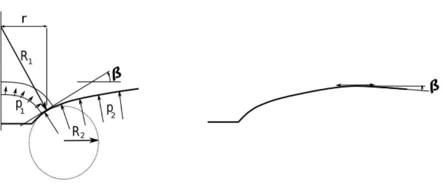
p2 p 1 r R1 R2
Figure 1: Pressures and curvatures for an axisymmetric model.
2. Introduction
The surface tension γ, assumed constant, equilibrates a pressure p exerted on the surfacep = −1
3 (σ11+ σ22+ σ33). This pressure is traditionally given
by: p = γ R1 + γ R2 (1) where R1 and R2 are the radii of curvatures of the surface. In the case of an
axisymmetric model, see Fig. 1 and 2, the two radii of curves are given by:
R1 =
r
sinβ (2)
where β is a function of r. Note that tanβ = ∂δ∂r and
R2 = (1 + δ′2)3/2 δ” (3) where δ is a function of r, δ′ = ∂δ ∂r and δ′ = ∂2 δ
∂r2. Consider p the pressure
"under" the surface, i.e. z < 0. It should be noted that β > 0 ⇒ p(R1) < 0
and δ” > 0 ⇒ p(R2) < 0. From the equ. 1 it therefore comes in the absence
of gravity:
p = −γ(sin (atanδ′)
r +
δ”
(1 + δ′2)3/2) (4)
This equation can be rewritten p = −γ(r√δ′ 1+δ′2 +
δ” (1+δ′2)3/2).
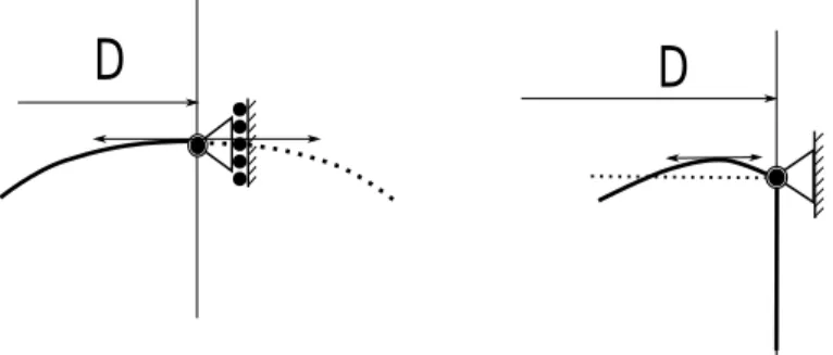
Fig. 3 presents two possible boundary conditions. Only the right-hand condition corresponding to a finite medium will be considered further on,
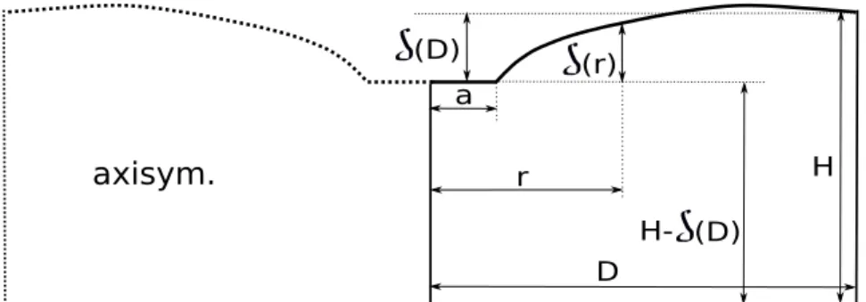
axisym. D a F z r r
Figure 2: Model geometry.
D
D
Figure 3: Two boundary conditions corresponding to a pseudo-periodic situation where the surface is tangent to the initial plane (left) and fixed edge (right).
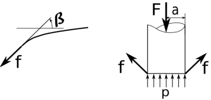
a
F
p
f
f
f
Figure 4: Flat punch equilibrium.
the pseudo-periodic medium condition not being of immediate interest. The balance of the flat punch is given by (see Fig. 4):
F = 2πaf + πa2p (5)
where f denotes the surface tension at the corner of the punch given by f = γsin(β(a)).
3. Shape of the surface - solution for low rotations 3.1. Constitutives equations
For β << 1 one can approximate sinβ ≈ β et atanδ′ ≈ β and it comes
p+γ(sin (atanδr ′)+ δ”
(1+δ′2)3/2) ≈ p+γ(δ ′
r+δ”).The differential equation to solve,
in the absence of gravity, is therefore:
p + γ(δ
′
r + δ”) = 0 (6)
If we want to fix δ(a) = 0 the solution is given by:
δ = c log(r a) −
p(r2−a2)
4γ (7)
where c is a constant defined by the inclination of the surface sin(β(a)) at the corner of the flat punch. From δ′(r) = c
r − pr 2γ it comes: δ = (aβ(a) +p a 2 2γ ) log( r a) − p(r2−a2) 4γ (8)
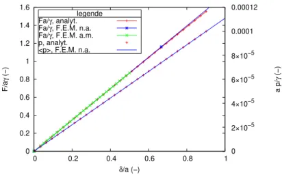
0 0.2 0.4 0.6 0.8 1 1.2 1.4 1.6 0 0.2 0.4 0.6 0.8 1 0 2×10⁻⁵ 4×10⁻⁵ 6×10⁻⁵ 8×10⁻⁵ 0.0001 0.00012 F/a γ (−) a p/ γ (−) δ/a (−) legende Fa/γ, analyt. Fa/γ, F.E.M. n.a. Fa/γ, F.E.M. a.m. p, analyt. <p>, F.E.M. n.a.
Figure 5: Reaction force on flat punch and liquid pressure versus indentation depth for a = 100nm, γ = 0.03N/m, D = H = 100a, K = 2GP a. For finite element calculations (F.E.M.) the elasticity of the solid is such that µ = 1P a.
From equ. 5, one deduces p = F π a2 − 2γsinβ(a) a and hence: δ = F 2πγlog( r a) + 1 2( F 2πγ −aβ(a))(1 − r2 a2) (9)
In practice, given an expected accuracy level of the order of one percent, the calculations will be conducted up to β = 0.25 rad ≈ 14.3 deg2
. Fig. 5 shows that pressure and force vary almost linearly with loading for small values of δ. Finite element calculations are consistent with this remark. These will be detailed elsewhere and discussed later. It will therefore be possible to consider the stiffness values F/δ et p/δ since the evolutions are linear at the beginning of the loading.
4. Solution for any rotations
For the intended objective, i. e. the determination of indentation stiff-ness, the solution to large rotations is - for the time being - only of minor interest. However, a calculation by numerical integration of the eq. 4 has been developed. The line segment defined by the two points a and D at z = 0, i. e. (a, 0) − (D, 0), is discretized into sub-segments (ri, 0) − (ri+1, 0), i ranging
2
from 0 to n with r0 = a and rn= D. Note ba= log10(a) and bD = log10(D),
the discretisation is done so that ri = 10ba+(i/n)(bD−ba). The surface is
com-posed of line segments (ri, δi) − (ri+1, deltai+1). Given an angle β(a), the first
segment is given by (r0, 0)−(r1, δ1) or δ1denotes (r1−a)(tan(β(a))). In order
to know the next points (r2, δ2) then (ri, δi) a dichotomy procedure looks for
the value of δi which respects the eq. 4 with an accuracy of abs(δ m
i −δm−1i
δi−1−δi−2)
typi-cally 10−4 where m denotes the iteration by dichotomy to find δ
i. The curves
δ′ and δ” are calculated from the second degree polynomial which passes
through the three points (ri, δi), (ri+1, δi+1) and (ri+2, δi+2m ). The slope δ′ is
the slope of the polynomial function in the middle of the segment. When δn
has been calculated, the procedure comes back from (rn, δn) and (rn−1, δn−1).
If the "round trips" do not overlap, the result of the calculation should be re-jected and an attempt should be made to increase the required discretisation size and accuracy.
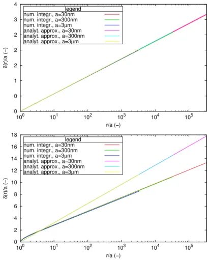
Fig. 6 compares the surface profiles for a = 30nm, a = 300nm and a = 3µm considering that D = 1cm in the absence of gravity force for γ = 0.03J/m2 and for p = 0. The discretisation considers n = 300 segments. For
relatively small rotations, typically β(a) < 0.25rad the numerical integration of the unsimplified differential equation agrees with the analytical solution approximated at small angles. It appears that at large rotations, here β(a) = 1.4rad, the surface profile also follows an evolution of the type δ(r) ∼ log(r). The approximate solution valid at small angles overestimates the depression δ(a) for a given force.
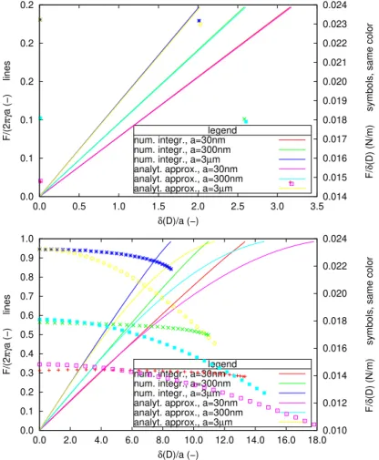
The Fig.Fig. 7 shows that the slopes F (δ(D))/δ(D) estimated with the approximate equations at small angles allow a very good approximation of the force as a function of the displacement of the flat punch to angles at the corner of the punch approaching 80◦.
Of course, the solutions presented here do not correspond to terrestrial observations of the surface of a fluid since in reality the perturbation brought by a floating microscopic object tends towards zero to infinity, i.e. δ(r) 6= log(r). Indeed, since gravity has been neglected until now, this trend is not achieved. The effects of gravity will be discussed below.
5. Volume variation and pressure balance - results for low rotations 5.1. Constitutive equations
If the volume is finite, this volume of material can be calculated knowing the shape of the surface. Recall that δ is computed from r = a in the
0 0 1 2 2 2 3 4 100 101 102 103 104 105 δ (r)/a (−) r/a (−) legend
num. integr., a=30nm num. integr., a=300nm num. integr., a=3µm analyt. approx., a=30nm analyt. approx., a=300nm analyt. approx., a=3µm
0 2 4 6 8 10 12 14 16 18 100 101 102 103 104 105 δ (r)/a (−) r/a (−) legend
num. integr., a=30nm num. integr., a=300nm num. integr., a=3µm analyt. approx., a=30nm analyt. approx., a=300nm analyt. approx., a=3µm
Figure 6: Profils de surface, comparaison de la solution analytique approximative val-able pour les petites rotations avec celle fournie par intégration numérique de l’équation différentielle du second ordre. En haut β(a) = 0.25rad et en bas β(a) = 1.4rad.
0.0 0.1 0.1 0.2 0.2 0.2 0.0 0.5 1.0 1.5 2.0 2.5 3.0 3.50.014 0.015 0.016 0.017 0.018 0.019 0.020 0.021 0.022 0.023 0.024 F/(2 πγ a (−) lines F/ δ
(D) (N/m) symbols, same color
δ(D)/a (−) legend num. integr., a=30nm num. integr., a=300nm num. integr., a=3µm analyt. approx., a=30nm analyt. approx., a=300nm analyt. approx., a=3µm
0.0 0.1 0.2 0.3 0.4 0.5 0.6 0.7 0.8 0.9 1.0 0.0 2.0 4.0 6.0 8.0 10.0 12.0 14.0 16.0 18.0 0.010 0.012 0.014 0.016 0.018 0.020 0.022 0.024 F/(2 πγ a (−) lines F/ δ
(D) (N/m) symbols, same color
δ(D)/a (−) legend num. integr., a=30nm num. integr., a=300nm num. integr., a=3µm analyt. approx., a=30nm analyt. approx., a=300nm analyt. approx., a=3µm
Figure 7: Courbes de chargement, comparaison de la solution analytique approximative valable pour les petites rotations avec celle fournie par intégration numérique de l’équation différentielle du second ordre. En haut β(a) = 0.25rad et en bas β(a) = 1.4rad.
r (r) H D (D) a H- (D) axisym.
Figure 8: Axisymétrical volume defined with D and H.
preceding equations that define the shape of the surface from the flat punch, i. e. δ(a) = 0. For a diameter D and an initial height H in the absence of solicitation of the indenter, i. e. δ(r) = 0 ∀r, the current height at the distance r is given by H − δ(D) + δ(r) (see Fig. 8). The current volume Va
is therefore:
Va= πD2(H − δ(D)) +
Z D a
δ(r)2πrdr (10)
which leads to:
Va= πD2(H − δ(D)) + π 8[D 2(4c(2log(D a) − 1) − p(D2−2a2) γ ) + a 2(4c −a2p γ )] (11) The result of the integral has been of course validated by numerical inte-gration. The initial volume Vi is given by Vi = πD2H. The pressure can be
deduced from the variation of volume knowing the bulk modulus K of the medium so that3
:
p = KVi−Va Vi
(12) The pressure p intervenes in the calculation of δ, équ. 8, therefore in the computation of V − a. The equations 12 and 8 must be satisfied simultane-ously. A numerical procedure can find the pressure p with less than 10−4 of
deviation to satisfy the problem in the finite medium. An accuracy of 10−4
on the pressure gives an accuracy of 10−4, even better in most cases, on the
estimate of the force F .
3
0 0.02 0.04 0.06 0.08 0.1 0 20 40 60 80 100 120 0 0.01 0.02 0.03 0.04 0.05 0.06 0.07 0 2 4 6 8 10 δ /a (−) δ/a (−) r/a (−) r/a (−) legend liquid F.E.M.
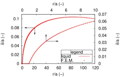
Figure 9: Example of the surface profile obtained by this analytical solution at small angles and by finite element with a zoom near the punch.
5.2. Finite element validation
Fig. 9 compares the surface profiles calculated with this analytical solution at small angles and finite element for a = 10nm, H = D = 120a, K = 2GP a, γ = 0.03N/m and µ = 1P a for finite element4
. The agreement is very appropriate. For the estimated pressures, the average pressure < p > resulting from the finite element calculation is 21.99P a and that provided by the analytical calculation is 22.00P a. For the estimated forces acting on the flat punch for δ = 0.1 a = 10−9m, the force resulting from the finite
element calculation is 4.9768 10−11N and the force provided by the analytical
calculation is 4.925 10−11N, a difference of 1%. The numerical finite element
procedure will be presented in another article, the purpose of this article is to provide mutual validation for finite element calculations. From equ. 5 we can deduce the contribution of the pressure p under the indenting flat punch and the ratio 2πafπa2p = a pf is 1.4 10−4 for the above parameter set.
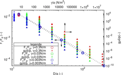
Fig. 10 provides the contribution of the pressure under the punch related to the surface tension at the corner of the flat indenter for a ∈ [10−8m; 10−3m],
γ ∈ [3 10−3N/m; 3 10−1N/m], D ∈ [12.5a; 200a] and H ∈ [12.5a; 200a]. The
dotted lines correspond to a = 10−7m, γ = 3 10−2N/m and D = H. It
appears that the contribution of the pressure under the indenter is negligible
4
10−4 10−3 10−2 101 102 10 −10 10−8 10−6 10−4 10−2 100 102 104 10 100 1000 10000 100000 1×10⁶ 1×10⁷ Fγ /Fp (−) g ρδ /p(−) D/a (−) γ/a (N/m2) legende Fγ/Fp, γ=0.3N/m gρδ/p, γ=0.3N/m Fγ/Fp, γ=0.03N/m gρδ/p, γ=0.03N/m Fγ/Fp, γ=0.003N/m gρδ/p, γ=0.003N/m
Figure 10: Contribution of the pressure under the indent to the line voltage at the corner of the flat punch (circles) and pressure related to the gravity related to the pressure in the liquid induced by the indentation (triangles).
compared to the contribution of the surface tension, which in all cases is less than 2%.
5.3. Case of negligible effect of gravity in finite media
When D/a → ∞ the solution that neglects gravity may no longer be satisfactory since it predicts Fδ →0. If the gravity forces g act according to the axis −−z with the dimension H, it is necessary to modify the equation of→ pressure with −ρgδ, where ρ indicates the density of the liquid. The complete equation of the static problem becomes:
p − ρgδ = −γ(sin (atanδ
′)
r +
δ”
(1 + δ′2)3/2) (13)
Indeed, gravity induces a pressure gradient below the surface, the pressure difference at the distance r is worth ∆p(r) = ρgδ(r). Fig. 10 provides the value of the gravity pressure related to the pressure in the liquid under the effect of indentation for a ∈ [10−8m; 10−3m], γ ∈ [3 10−3N/m; 3 10−1N/m],
D ∈ [12.5a; 200a] and H ∈ [12.5a; 200a]. The dotted lines correspond to a = 10−7m, γ = 3 10−2N/m and D = H. The top line corresponds to gρδ
Phyd
for D = H = 50a. In practice for the problems that are concerned here ∆p(r) ∼ 1000 9.81 a. Let us not forget that it is a question of providing
validation arguments in finite media for which typically D/a < 2005
. For γ/a > 104the ratio ∆p(r)/P
hydis always less than typically 1%. For typically
γ = 0.03N/m this leads to the validation of the negligible gravity assumption for a < 3µm. For example, for a = δ = 1µm, H = D = 120a we get p = 2.2P a and ∆p ≈ 0.01P a. However, for larger values such as a = δ = 0.1mm, we obtain p = 0.022P a ∆p ≈ 1P a, always for H = D = 120a. It appears that the pressure gradient related to subsurface gravity is therefore negligible for the precision sought in the range of material parameters of a microscopic indentation of an organic material.
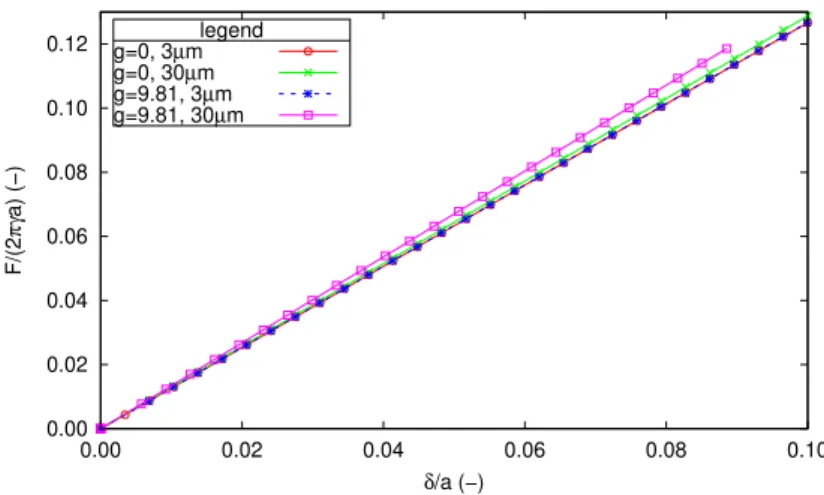
For the objective pursued, it was therefore not necessary to seek to solve the equation analytically 13. However, since finite element calculations have proved their worth, it is possible to use them to confirm these state-ments. Fig. 11 shows the isovalues of hydrostatic pressure for a = 30µm, γ = 0.03J/m2, g = 9.81m/s2, K = 2GP a, µ = 1P a. The D dimension has been
set at 12.5a for a better readability of the figure. It appears that the pres-sure is slightly higher below the punch than further below the surface due to the difference in altitude. The Fig. 12 shows the normalized force curves (2πγaF ) versus normalized indentation depth (δa) for a = 3µm, a = 30µm, D = 120a, γ = 0.03J/m2, g = 0m/s2, g = 9.81m/s2, K = 2GP a, µ = 1P a and
ρ = 1000kg/m3 where ρ denote the density of the material. We can see that,
for the parameter sets of interest to us, the effect of gravity begins to appear when the size of the punch exceeds a few micrometers. Indeed, for a = 3µm the curves overlap while for a = 30µm they differ. As expected, gravity tends to increase the force for a given depression. For very large values of D/a, gravity must always be taken into account as for large values of a. It is easy to estimate roughly the validity limit of gravity consideration. Suppose that the force related to the surface tension is of the same order as the force
5
indeed, choosing values of D/a in the order of 102
for the finite element model is sufficient to obtain a very good agreement with the values predicted by the Boussinesq model which considers a semi-infinitemedium. Indeed, finite element stiffness predictions F/δ tend towards the asymptotic value predicted by Boussinesq. On the other hand, when only the surface tension is sensitive, the response of the medium always depends on D a
regardless of the values of D
a. Finite element stiffness predictions F/δ do not tend to be
asymptotic in this case. The analytical and numerical approaches are also in agreement in this case, which validates the analytical and numerical approaches
Figure 11: On the left deformed amplified 20 times, on the right isovalues of hydrostatic pressure showing the effect of gravity for a = 30µm, D = 12.5a, γ = 0.03J/m2
, g = 9.81m/s2 , K = 2GP a, µ = 1P a and ρ = 1000kg/m3 . 0.00 0.02 0.04 0.06 0.08 0.10 0.12 0.00 0.02 0.04 0.06 0.08 0.10 F/(2 πγ a) (−) δ/a (−) legend g=0, 3µm g=0, 30µm g=9.81, 3µm g=9.81, 30µm
Figure 12: Normalized force versus normalized indentation depth curves for D = 120a, γ = 0.03J/m2
, K = 2GP a, µ = 1P a and ρ = 1000kg/m3
exerted by the pressure under the punch. Let’s pose: F 2 ∼ 2πγδ log(D/a) ∼ πa 2p (14)
I comes Da ∼ exp(ρa2γ2g). Consider gamma = 0.03J/m2, ρ = 1000kg/m3
and g = 9.81m/s2. For a = 3mm we get D/a ≈ 2 which indicates that
for D >> a the surface tension has a second order effect on the F force. For a = 1mm we obtain D/a ≈ 450 which indicates that we must typically consider D ∼ 1000a and take into account simultaneously gravity and surface tension in a numerical simulation to properly estimate the force F . Finally, for a < 1mm, very quickly D/a → ∞ which indicates that it is difficult to carry out a numerical finite element simulation for a nanoscopic indenter in a case where gravity would have an influence.6
6. Discussion
Fig. 13 presents the standard stiffnesses for the force acting on the flat punch (circles) and the pressure in the liquid under the effect of indentation (triangles) as a function of the medium size ratios for the parameter sets a ∈ [10−8m; 10−3m], γ ∈ [3 10−3N/m; 3 10−1N/m], D ∈ [12.5a; 200a] and H ∈
[12.5a; 200a]. The dotted lines correspond to a = 10−7m, γ = 3 10−2N/m and
D = H. It appears that the values of F/δγ depend on D/a but few on H/a. The pressure p induced in the liquid is sensitive to the dimension H although this pressure has little influence on the reaction on the indenter in the range of parameters considered here. The Fig. 14 shows that below a certain shear modulus, typically for µ < 100P a, a compressible solid can be considered as a liquid of same compressibility with respect to microindentation in the presence of surface tension. To the extent that finite element calculations are available and provide satisfactory results, if necessary, all cases that do not lend themselves to simplification, such as when the effect of gravity can no longer be neglected, may be treated on a case-by-case basis.
6
A following study will lift the aberration δ(D) → ∞ when D → ∞ since it doesn’t correspond to observations in the presence of gravity. Indeed, to infinity - far from the indenter - the surface tangents the horizontal, i.e. the perturbation of the surface profile linked to a floating object tends towards zero.
100 101 101 102 10−6 10−5 10−4 10−3 10−2 10−1 F/ δγ (−) a 2 p/ δγ (−) D/a (−) legende F/δ, γ=0.3N/m p/δ, γ=0.3N/m F/δ, γ=0.03N/m p/δ, γ=0.03N/m F/δ, γ=0.003N/m p/δ, γ=0.003N/m
Figure 13: Normalized stiffnesses for the force acting on the flat punch (left axis, circles) and the pressure in the liquid under the effect of indentation (right axis, triangles) as a function of the size ratios of the medium.
10−1 100 100 101 102 103 104 105 106 1.00 10.00 (F/ δ )FEM solid (N/m) (F/ δ )FEM solid / (F/ δ )analyt. liquid (−) γ/aµ (−) legende D=H=5a D=H=10a D=H=20a D=H=40a D=H=80a D=H=120a D=H=160a D=H=5a D=H=10a D=H=20a D=H=40a D=H=80a D=H=120a D=H=160a
Figure 14: Curves of apparent stiffness of the solid material under indentation as a function of the dimensionless parameter γ/aµ (left axis, lines and symbols) and comparison with the stiffness of liquid with the same compressibility (right axis, lines) for a = 10nm, γ = 0.03N/m, K = 2GP a. The apparent stiffness of the liquid is obtained analytically, that of the solid by finite element.
7. Conclusion
The calculations presented in this article for a liquid are consistent with those for tightly strained membranes (Fond, 2018b), (Fond, 2018a). They make it possible to locate the domains of validity to allow to neglect certain parameters. They provide validation arguments for numerical finite element calculations. Given the relatively large volume of information required to properly present this numerical model, it will be presented in a separate article.
Appendix A. Comparison of highly stretched membrane and com-pressible liquid with surface tension
In order to obtain the initial slope of the curve F vs δ, i.e. the ap-parent stiffness of the material, the indentation depths are chosen so that δ/a < 0.1. Fig. A.15 shows the results for a = 10−8m, γ = 3 10−3N/m,
D ∈ [12.5a; 3200a], H ∈ [12.5a; 3200a] and K = 2GP a for the liquid model. This figure shows that the force predicted by the liquid model with surface tension is always higher than that of the highly prestressed membrane model. The solution for liquids with surface tension will be more suitable for almost uncompressible materials. As stated in §5.2, the contribution of pressure under the indentor, second term of the equation 5 is a second order term. Nevertheless, the relatively small pressure generated by the compression of the liquid slightly changes the shape of the surface and, in particular, in-creases the angle at the corner of the indenter so that the force acting on the flat punch is slightly greater than for a highly stretched membrane under the same conditions. Fortunately, the results of the Tab. A.1 show that the ratio between the forces predicted by the compressible liquid model with surface tension and the highly prestressed membrane model is almost constant when only the parameter H varies and for values of gamma/a > 3 106P a7
. This allows to simply use the approximate formula provided in (Fond, 2018b), i. e. δ(D) ≈ 2πγF log(D/a), with a correction coefficient to move from one model to another.
F ≈ cM L(D/a)
2πγδ
log(D/a) (A.1)
7
for higher values of gamma/a it should be considered that the correction to be made is not constant, and this more so when H is small
1.20 1.25 1.30 1.35 1.40 1.45 1.50 1.55 1.60 1.65 102 F log(D/a)/2 πδγ (−) H/a (−) legend D=12.5a D=25a D=50a D=100a D=200a
Figure A.15: Comparison between the compressible liquid model with surface tension and the highly prestressed membrane model.
For semi-infinite media and quasi-incompressible materials8
, it will therefore be appropriate to use as an analytical reference when aµγ << 1 the Boussinesq equation F = 8aµδ and when amuγ >> 1 the equation provided above F ≈
cM L(D/a) 2πγδ
log(D/a) . It is possible to approximate by a function in the interval
D/a ∈ [12.5a; 3200a] to get:
F ≈ (1.13 + 2.19D a
−0.59
) 2πγδ
log(D/a) (A.2) Fond, C., 2018a. Enfoncement d’un poinçon plat dans une membrane
forte-ment précontrainte : solution analytique.
Fond, C., 2018b. Indentation of a highly prestressed membrane by a flat punch: analytical solution.
8
within the range of parameters considered here suitable for organic materials and nanometric to micrometric indenters
D/a cM L(H/a = 12.5) cM L(H/a = 200) 12.5 1.6407 1.6260 25 1.4484 1.4461 50 1.3430 1.3426 100 1.2773 1.2772 200 1.2326 1.2326 400 1.2003 1.2003 800 1.1759 1.1759 1600 1.1568 1.1568 3200 1.1414 1.1414
Table A.1: Relations between the stiffness predicted by the liquid and tensile membrane models, influences of D/a and H/a.
1.10 1.20 1.30 1.40 1.50 1.60 101 102 103 cML (−) D/a (−) legend H=12.5a H=200a fit
Figure A.16: Change in coefficient cM L with D/a in the range H/a ∈ [12.5a; 3200a],
D/a ∈ [12.5a; 3200a] and γ/a > 3 106