Publisher’s version / Version de l'éditeur:
Vous avez des questions? Nous pouvons vous aider. Pour communiquer directement avec un auteur, consultez la première page de la revue dans laquelle son article a été publié afin de trouver ses coordonnées. Si vous n’arrivez pas à les repérer, communiquez avec nous à PublicationsArchive-ArchivesPublications@nrc-cnrc.gc.ca.
Questions? Contact the NRC Publications Archive team at
PublicationsArchive-ArchivesPublications@nrc-cnrc.gc.ca. If you wish to email the authors directly, please see the first page of the publication for their contact information.
https://publications-cnrc.canada.ca/fra/droits
L’accès à ce site Web et l’utilisation de son contenu sont assujettis aux conditions présentées dans le site LISEZ CES CONDITIONS ATTENTIVEMENT AVANT D’UTILISER CE SITE WEB.
The 18th International Conference on Surface Modification Technologies
[Proceedings], 2004-11-18
READ THESE TERMS AND CONDITIONS CAREFULLY BEFORE USING THIS WEBSITE. https://nrc-publications.canada.ca/eng/copyright
NRC Publications Archive Record / Notice des Archives des publications du CNRC :
https://nrc-publications.canada.ca/eng/view/object/?id=aac4baf2-7d38-4f0b-bcad-afbebfec7536
https://publications-cnrc.canada.ca/fra/voir/objet/?id=aac4baf2-7d38-4f0b-bcad-afbebfec7536
NRC Publications Archive
Archives des publications du CNRC
This publication could be one of several versions: author’s original, accepted manuscript or the publisher’s version. / La version de cette publication peut être l’une des suivantes : la version prépublication de l’auteur, la version acceptée du manuscrit ou la version de l’éditeur.
Access and use of this website and the material on it are subject to the Terms and Conditions set forth at
Residual Stress Analysis of Laser-cladded Al/Si Coatings onto
Aluminium Alloy Substrates
IMI2004-106132-G
CNRC
47568
Residual Stress Analysis of Laser-cladded Al/Si Coatings onto Aluminium
Alloy Substrates
L. DUBOURGa,I, F. HLAWKAb, A. CORNET"
a Aluminium Technology Centre, National Research Council Canada, 501, Boul. de l'Universite, Saguenay (Quebec) G7H 8C3 Canada. E-mail: laurent.dubour~@cnrc-nrc.gc.ca
b Laboratoire d'lngenierie des Surfaces de Strasbourg, ENSAIS, 24 bd de la victoire, 67000 Strasbourg, France. E-mail: f.hlawka@insa-strasbour~.fr
CLaboratoire d'lngenierie des Surfaces de Strasbourg, ENSAIS, 24 bd de la victoire, 67000 Strasbourg, France.
E-mail: a.comet@insa-strasbourg.fr
I Corresponding author: Tel. +1 418545-5098; Fax +1 418545-5345 (L. Dubourg)
ABSTRACT
Surface properties of aluminium alloys (particularly hardness, elastic modulus and wear resistance) can be significantly improved by laser cladding. This high energy process causes thermal stresses, which lead to the appearance of residual stresses and substrate distortions. In this study, laser cladding was applied to a 5052 aluminium alloy using a cw Nd:Y AG laser and coaxial injection of Al 50Si powders. Residual stresses were quantified by X-ray diffraction and by sample strain measurements. The differences in the results obtained by these two methods highlighted the influence of the heat-affected zone (HAZ) underlying the coating. A model of three strain domains has explained these differences: the coating, the HAZ and the substrate. Experiments identified an optimal treatment speed, leading to maximum compression stresses, which improve hardness and wear resistance. Moreover, at a certain fixed speed, thermal stresses balanced each other in the sample leaving the substrate undistorted.
II
,
1.0 INTRODUCTION
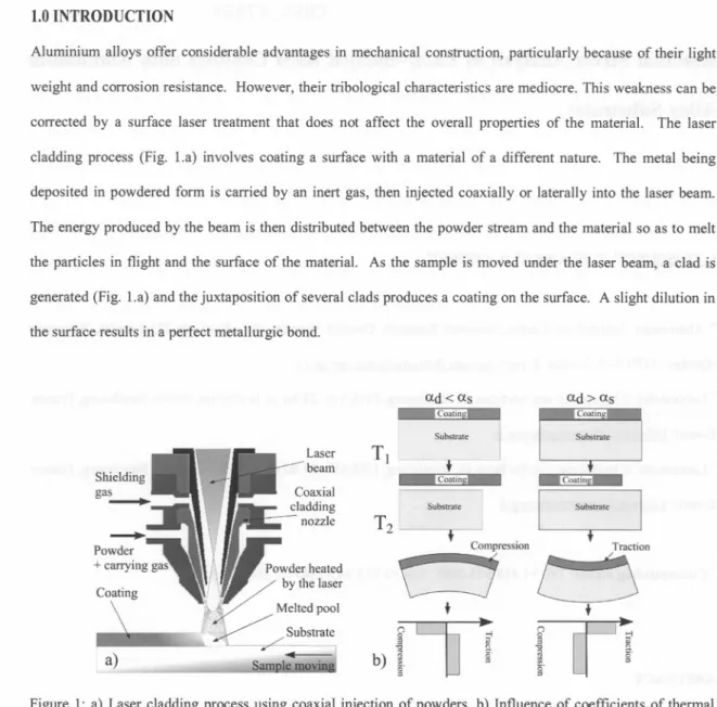
Aluminium alloys offer considerable advantages in mechanical construction, particularly because of their light weight and corrosion resistance. However, their tribological characteristics are mediocre. This weakness can be corrected by a surface laser treatment that does not affect the overall properties of the material. The laser cladding process (Fig. 1.a) involves coating a surface with a material of a different nature. The metal being deposited in powdered form is carried by an inert gas, then injected coaxially or laterally into the laser beam. The energy produced by the beam is then distributed between the powder stream and the material so as to melt the particles in flight and the surface of the material. As the sample is moved under the laser beam, a clad is generated (Fig. 1.a) and the juxtaposition of several clads produces a coating on the surface. A slight dilution in the surface results in a perfect metallurgic bond.
ad < as Coatin ad>as Coatin Substtate Sub!.1nIte Laser beam TJ ur CoatinSj _Coatin~
~
Ubsttate Substtate TractionU'-L;
t
T2 i
~
a)
(") 0 3b)
1.
g ...,~
c.=
(") g -5~
cr=
i
c.=
Figure 1: a) Laser cladding process using coaxial injection of powders, b) Influence of coefficients of thermal expansion (CTE) on the residual stresses (ad: CTE of the coating, as: CTE of the substrate, T2: temperature during the treatment, TI: room temperature).
As with other high energy surface treatments, laser cladding creates thermal stresses that can result in residual stresses and eventually distort the sample. According to Sue et al., [1], the residual stresses can be modelled as per Eq. 1, using the sum of intrinsic and thermal stresses. The intrinsic stresses correspond to the structural modifications of the material during treatment: diffusion, enlargement of the grains and variation in the dislocation density. In the case of laser cladding, a high energy process, thermal stresses predominate. They are generated by the difference in contraction during cooling between the coating and the substrate. As can be seen in Fig. 1.b, the coating has the same dimension as the substrate during treatment (temperature T2). During
1.6 ~
:!:
E; 1.4g
>
"'C 1.2 CI.I CI.I c.. (/) C> 1.0 .!: c: c: (\J~
0.8.
.
cr(MPa) 60.0 40.0 20.0 10 -20.0 -40.0 -60.0 -80.0 -100 -120 -140 -160.
.
6 8 10 12 14Powder feeding rate Q (g.min'1)
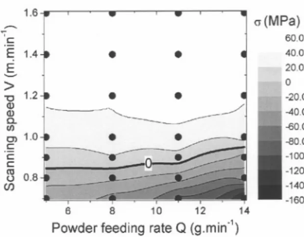
Figure 2: Residual stress measurements in the coatings (MPa) using the strain method. InflL'eJ1ce operating parameters: scanning speed (V) and powder feed rate (Q).
3.2 Stress Measurement Using XRD
The measurements oflongitudinal and shearing stresses carried out by XRD as a function of sC3nni:iio-,')e presented on Fig. 3. Measurements were taken through the depth of each coating at 0.1 mm inten a" do the interface with the substrate. The powder feed rate was set at an intermediate rate of 11 gJI1;11"i .
cooling to room temperature TI, the substrate contracts more than does the coating (case where the coefficient of thermal expansion (CTE) of the coating is less than that of the substrate: ad < as) resulting in compression stresses in the coating. Conversely, where ad > as, the coating is in tension since the substrate contracts less than does the clad. This phenomenon can be modelled using Eq. 2 [1].
(Yt
=
(Yi+
(Yth (1) CYtll= (ad-aJ(T2 -r;)~
(1- Vd)
(2)
[Eq. 1]: crt global stress, crj intrinsic stresses, cribthermal stresses.
[Eq. 2]: ad: CTE of the coating, as: CTE of the substrate, Ed and Vd: Young modulus and Poisson coefficient of
the coating, T I room temperature, T 2 temperature during treatment.
The residual stresses have a critical influence on the behaviour and the lifespan of mechanical parts. Along with external stresses, they serve to modify the real value of the applied load. Consequently, with the recent development of laser cladding, it was essential to understand these phenomena. Also, by controlling residual stresses it is possible to limit the distortion of samples after treatment and to increase the compressive stress in coating in order to increase the hardness and wear resistance. This article therefore presents the influence of the main treatment parameters (scanning speed and powder feed rate) on the range of residual stresses. These stresses were measured using two different techniques: the strain method and XRD.
2.0 EXPERIMENTAL PROCEDURE
The cladding was carried out using a cw 2000 W Nd:YAG laser with a wavelength of 1.064 !lm and 1 mm diameter optical fibre. The Nd:Y AG laser was chosen based on the fact that the aluminium substrate has an absorption coefficient at this wavelength twice that of the CO2 laser [2]. A 300 mm focal length lens was used to focus the beam. The operating parameters used were as follows: laser power of 1700 W on the workpiece, 2.7 mm diameter circular beam on the sample with an energy density of 300 W.mm-2. The laser beam was maintained in the vertical, whereas the surface of the substrate was inclined 5° to the horizontal. Normal incidence was not used to avoid the risk of beam reflection that could damage the optical fibre. The composition of the powder used was Al 50Si (wt.%) with a granulometry between 45 and 90 !lm. These coatings were the subject of a metallographic study conducted by Pei et al. [3]. The powder was injected at rates varying from 5 to 14 g.min-l depending upon the coating, using argon at 1 bar pressure and a flow rate of 3 l.min-I. The samples were placed on a X-Y stage that moved under the beam at scanning speeds varying from 0.7 to 1.6 m.min-I. The
substrates
weremadefrom a commercialaluminiumalloy 5052(AI
+
3 wt.% Mg) and measured75 x 8 x 6mm3. We chose this non-hardenable alloy in order to minimise the intrinsic stresses and to analyse particularly the effects of thermal stresses (see Eq. 1). Surfaces to be clad were abraded with grade 120 SiC paper then cleanedwith acetone. Thesamples were then annealed at 150°C for 24 hours to relax the residual stresses from rolling and present a homogenous microstructure. The laser cladding was then produced over the entire length
of the substrate.
The strain method consisted in measuring sample distortion after laser cladding and calculating overall stresses in the coating using Eq. 3. This technique was used by Tomlinson et at. [4] on different aluminium surface alloys produced by laser (AI-Fe and AI-Cu alloys). In our case, sample distortion was measured using an extended field confocal microscope [5] with vertical resolution of:t 0.01 Ilm and lateral resolution of:t 2 Ilm. The sampling step was 5 Ilm in X direction. The strain and curvature radius of the sample were then approximated by a parabolic equation. The elastic modulus of the coating Ed and substrate Es were set respectively at 89 and 69 GPa [6]. Moments of inertia Id and Is were calculated for each sample according to the dimensions of the coating. Each result represented the average of measurements conducted on 3 samples. A similar approach was used by Teixeira et at. [7] in the case of residual stress measurements in PVD coatings.
(jd
=
(EJs
+ EdId )y(Id +
::
Is)R(3)
[Eq. 3]: ad: stress in the coating, Es and Ed: Young modulus of the substrate and the coating, yand R: strain and radius of the sample after laser cladding, Is and Id: moments of inertia of the substrate and the coating.
In order to measure stresses in the depth of coatings, the clads were electrolytically polished with perchloric acid to successively remove material. This method has previously been used on laser surface alloys [8, 9]. Stress was measured along the clad length for the {31l} crystal plane of aluminium using a chrome anode (A= 0.2291 nm) and a Siemens D5000 diffractometer. We studied the diffraction peak located at 139.339° (oscillation:i: 1°, duration 6 min) [10]. The configuration worked on Q mode and included a linear detector with a 16° view angle and a 1 mm diameter circular slit.
3.0 RESULTS
3.1 Stress Measurements Using the Strain Method
Scanning speeds of 0.7 to 1.6 m.min-I and powder feed rates of 5 to 14 g.min"I were used, with experimental limits set according to the morphology of the clads obtained. For values less than 0.7 m.min.1 (scanning speed) or 5 g.min"1(powder feed rate), clads showed excessive and inconsistent dilution. For scanning speeds greater than 1.6 m.min.1 or powder feed rates greater than 14 g.min-1, the energy was not sufficient to ensure dilution and the metallic bond between the coating and the substrate. Fig. 2 shows the stress measurements using the strain method, with each point representing one speed/flow pair analysed. The level of residual stress is shown by contour curves and evolves between -160 and 60 MPa. Distortions associated with these stresses correspond to those in Fig. 1.b: samples with a convex form show a compressive state in the clad and conversely samples with a concave form result from tension in the clad.
The following phenomena can be observed:
(i) Results obtained using the strain method disagree with the model in Fig. Lb. In our case, the CTE of the coating (ad
=
14.10-<>m.m-I.K-I [6]) is less than that of the substrate (as = 24.10-<>m.m"I.K-1[6]). Therefore, according to Fig. 1.b, all coatings should be in compression and should show signs of convex distortion, regardless of operating parameters.(ii) Residual stresses increase when the scanning speed increases, moving IToma compressive to a tension state. For example, for a rate of 8 g.min"l, the coating is in compression (ad = -48MPa) at V = 0.7 m.min-I and in tension (ad
=
58 MPa) at V = 1.6 m.min-I.(iii) For low scanning speeds (V :'>0.8 m.min-I), residual compressive stresses increase enormously when the powder feed rate increases. For V = 0.7 m.min-l and Q = 14 g.min"" the maximum is -151 MPa, corresponding to a substantial compressive stress for aluminium (yield strength of 150 MPa).
(iv) For a speed of approximately 0.9 m.min"" samples show no distortion, with a zero residual stress level in the coating (black level curve in Fig. 2).
~
.~
E; 1.45
>
"t:J 1.2 Q) Q) a. I/) 0> 1.0 .~ c c (1]~
0.8 1.6.
.
cr(MPa) 60.0 40.0 20.0 10 -20.0 -40.0 -60.0 -80.0 -100 -120 -140 -160Figure 2: Residual stress measurements in the coatings (MPa) using the strain method.
.
.
6 8 10 12 14
Powder feeding rate Q (g.min")
operating parameters: scanning speed (V) and powder feed rate (Q).
3.2 Stress Measurement Using XRD
Influence of the
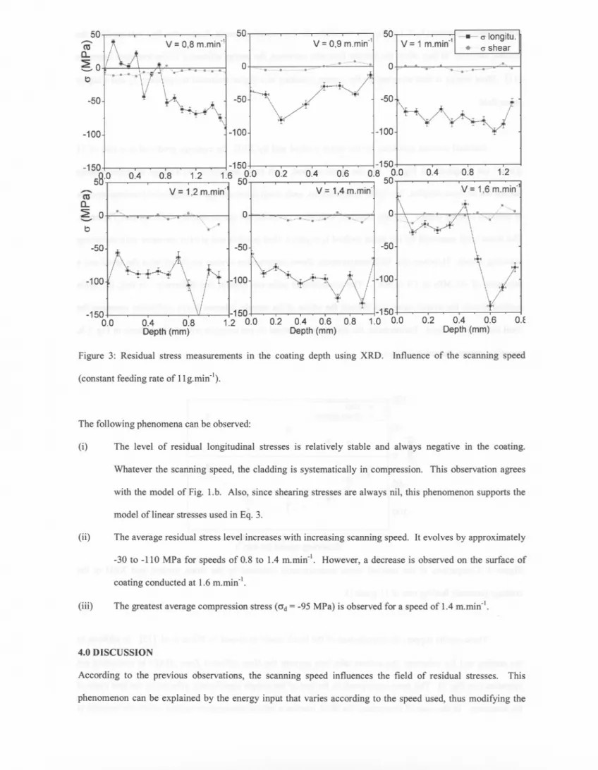
The measurements of longitudinal and shearing stresses carried out by XRD as a function of scanning speed are presented on Fig. 3. Measurements were taken through the depth of each coating at 0.1 mm intervals down to the interface with the substrate. The powder feed rate was set at an intermediate rate of 11 g.min-I. The scanning speed evolved trom 0.8 to 1.6 min-I.
50
-
caa.
~ 0
1,0-'-'" f.-o" o.,. t> 50v = 0,8 m.min" v = 0,9 m.min" 501
v
= 1 m.min-'.
1-0-
.
0"longitu.
shear'0_0-.'''--0-. .--0.. 0"1""'-"'0--'" 0 """ ".-: 0 "---50
.~
-50
-50 -100 -100 -100 -150, 58.0 0.4 -150 0.8 ,1.2 1.? 58.0 V = 1,2 m.min-0.2 0.4 0.6 -150 0.8 0.0 50 0.4 0.8 1.2-
caa.
~ 0 '0, '-'" V = 1,4 m.min- V = 1,6 m.min-'I i. 0 ... '~o o_-o'---~" / 0 /."""" '0--- \ ", " ../ --,/ t> -50 -50 -50 -100 -100 -100 -150 0.0 0.4 0.8 Depth (mm) ,-150 1.2 0.0 0.2 0.4 0.6 0.8 Depth (mm) ,-150 1.0 0.0 0.2 0.4 0.6 Depth (mm) O.fFigure 3: Residual stress measurements in the coating depth using XRD. Influence of the scanning speed (constant feeding rate of llg.min-l).
The following phenomena can be observed:
(i) The level of residual longitudinal stresses is relatively stable and always negative in the coating, Whatever the scanning speed, the cladding is systematically in compression. This observation agrees with the model of Fig. 1.b. Also, since shearing stresses are always nil, this phenomenon supports the model oflinear stresses used in Eq. 3.
(ii) The average residual stress level increases with increasing scanning speed. It evolves by approximately -30 to -110 MPa for speeds of 0.8 to 1.4 m.min-I. However, a decrease is observed on the surface of coating conducted at 1.6 m.min-l.
(iii) The greatest average compression stress (ad = -95 MPa) is observed for a speed of 1.4 m.min-I.
4.0 DISCUSSION
According to the previous observations, the scanning speed influences the field of residual stresses. This phenomenon can be explained by the energy input that varies according to the speed used, thus modifying the
temperature
difference(T2-T,) of Eq.(2).
Similarly,for low scanningspeeds,
thepowderflow ratemodifiesthe
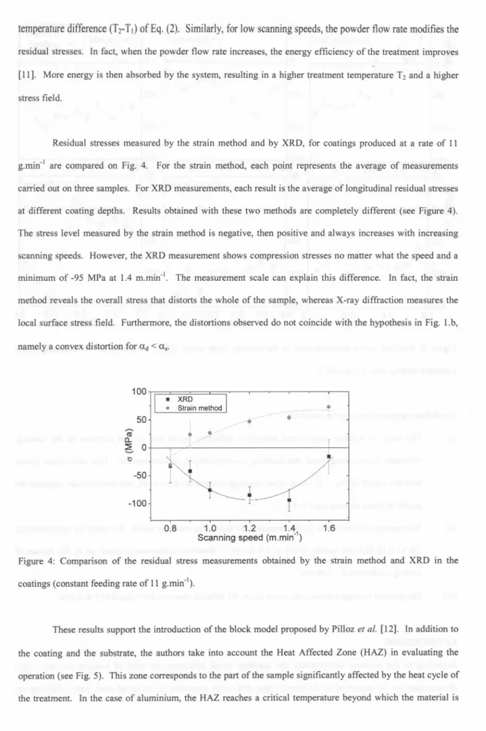
residual stresses. In fact, when the powder flow rate increases, the energy efficiency of the treatment improves [11]. More energy is then absorbed by the system, resulting in a higher treatment temperature Tz and a higher stress field.Residual stresses measured by the strain method and by XRD, for coatings produced at a rate of 11 g.min'l are compared on Fig. 4. For the strain method, each point represents the average of measurements carried out on three samples. For XRD measurements, each result is the average of longitudinal residual stresses at different coating depths. Results obtained with these two methods are completely different (see Figure 4). The stress level measured by the strain method is negative, then positive and always increases with increasing scanning speeds. However, the XRD measurement shows compression stresses no matter what the speed and a minimum of -95 MPa at 1.4 m.min,l. The measurement scale can explain this difference. In fact, the strain method reveals the overall stress that distorts the whole of the sample, whereas X-ray diffraction measures the local surface stress field. Furthermore, the distortions observed do not coincide with the hypothesis in Fig. 1.b, namely a convex distortion for ad < as.
100
.
XRD.
Strain method ...! 50 , . '.
.. ,/~
//J
//",
~.
.
tU
a..
5
0 \:) -50 -100 0.8 1.0 1.2 1.4Scanning speed (m.min.1) 1.6
Figure 4: Comparison of the residual stress measurements obtained by the strain method and XRD in the coatings (constant feeding rate of 11 g.min,I).
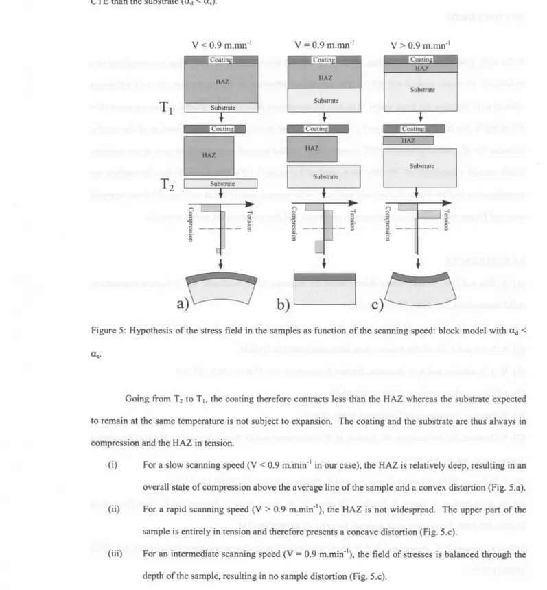
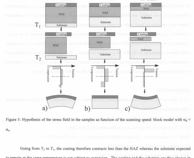
These results support the introduction of the block model proposed by Pilloz et al. [12]. In addition to the coating and the substrate, the authors take into account the Heat Affected Zone (HAZ) in evaluating the operation (see Fig. 5). This zone corresponds to the part of the sample significantly affected by the heat cycle of the treatment. In the case of aluminium, the HAZ reaches a critical temperature beyond which the material is
subject to plastic distortions due to thermomechanical effects. The substrate thus corresponds to the zone where the thermal effects of the process are negligible (we will assume that the temperature of the block remains equal to the room temperature Td. Fig. 5 illustrates this principle for various speeds and for a coating with a lower CTE than the substrate (ad < as).
v < 0.9 m.mn'I
v = 0.9 m.mn'lV> 0.9 m.mn'l
"":{Coatin 1 c::.°atin Coatin
HAZ
HAZ II" HAZ
Substrate
TI
Substrate Substrate + c~ + T Coatin.s.f
~
~,,-;"":JW;--- Ic;:J
G
f
~
I SubstrateT2
SubstrateIi
:]
" ;;i :;a
'" _.~
-- .-.- g g' ;;!a
g' (")~
; .o-j~
"""".' !i "g i!!. " 0 ::; = 0' =.
a)\---J
b)D
c)L-'~
Figure 5: Hypothesis of the stress field in the samples as function of the scanning speed: block model with ad < as.
Going from T2 to T., the coating therefore contracts less than the HAZ whereas the substrate expected to remain at the same temperature is not subject to expansion. The coating and the substrate are thus always in compression and the HAZ in tension.
(i) For a slow scanning speed (V < 0.9 m.rnin'l in our case), the HAZ is relatively deep, resulting in an overall state of compression above the average line of the sample and a convex distortion (Fig. 5.a). (ii) For a rapid scanning speed (V > 0.9 m.min'I), the HAZ is not widespread. The upper part of the
sample is entirely in tension and therefore presents a concave distortion (Fig. 5.c).
(iii) For an intermediate scanning speed (V = 0.9 m.min''), the field of stresses is balanced through the depth of the sample, resulting in no sample distortion (Fig. 5.c).
subject to plastic distortions due to thermomechanical effects. The substrate thus corresponds to the zone where the thermal effects of the process are negligible (we will assume that the temperature of the block remains equal
CTE than the substrate (ad < as).
to the room temperature T1). Fig. 5 illustrates this principle for various speeds and for a coating with a lower
v < 0.9 m.mn-I
v = 0.9 m.mn-I HAZ HAZTl
Substrate Substrate Coat!!!&ll Coatin.sj HAZ Substratec::J
I SubstrateT2
[
f
f
n:=]
- >oj~
~.
~
-- g c'"
>oj "" .JL.- g'v
> 0.9 m.mn-I
SubstrateT
~
r'H<\Z il[;J
11:E
>oj 0 "s
- &1"".
-,
~
g g' +a~
b)D
c)cJ)
Figure 5: Hypothesis of the stress field in the samples as function of the scanning speed: block model with ad < as.
Going from T2 to T(, the coating therefore contracts less than the HAZ whereas the substrate expected
compression and the HAZ in tension.
to remain at the same temperature is not subject to expansion. The coating and the substrate are thus always in
(i) For a slow scanning speed (V < 0.9 m.min-! in our case), the HAZ is relatively deep, resulting in an overall state of compression above the average line of the sample and a convex distortion (Fig. 5.a). (ii) For a rapid scanning speed (V > 0.9 m.min-\ the HAZ is not widespread. The upper part of the
sample is entirely in tension and therefore presents a concave distortion (Fig. 5.c).
depth of the sample, resulting in no sample distortion (Fig. 5.c).
For an intermediate scanning speed (V = 0.9 m.min-\ the field of stresses is balanced through the (iii)
The block model thus provides an explanation for the divergent phenomena observed using the strain method and XRD.
5.0 CONCLUSION
In the clads produced by laser cladding, the field of residual stresses was measured using two complimentary techniques: the strain method and XRD. The substantial difference in the results from the two techniques allowed us to introduce the block model to explain the phenomena observed. For a certain scanning speed (V = 0.9 m.min'I), the strain method indicated a balance of residual stresses, causing zero distortion of the sample. Likewise for all processing speeds, XRD measurement revealed residual compression stresses in the coatings, which reached a maximum of -95 MPa for a speed of 1.4 m.rnin'J. We then conclude that the methods are complimentary and the results obtained will enable us in the future to predict which surfaces will show improved wear and fatigue resistance due to compression constraints and also non-distorted coated materials.
6.0 REFERENCES
[1]: A Sue and G.S. Schajer, Stress determination for coatings, ASM Handbook, vol. 5 Surface engineering, ASM international OH, USA, (1994) 645-653.
[2]: J.C. Jules, J.M. Pelletier, M. Pilloz and A B. Vannes, Journal de Physique IV, vol. 1 (1991) 61-63. [3]: Y. T. Pei and J. Th. M. De Hosson, Acta Materialia (2000) 2671-2624.
[4]: W. J. Tomlinson and A S. Bransden, Surface Engineering, vol. 11 n04 (1995) 337-344 [5]: J. Cohen-Sabban, Mesure, n0719 (1999) 85-90.
[6]: R. Develay, Techniques de I'Ingenieur, M443 (1989).
[7]: V. Teixeira, M. Andritschky, W. Fischer, H. P. Buchkremer and D. Stover, Journal of Material Processing Technologies, vol. 92-93 (1999) 209-216.
[8]: L. Dubourg, F.Hlawka and ACornet, Journal de Physique IV, vol. 10 (2000) 137-144.
[9]: M. A McMahon, A Green, Z. Liu, K. G. Watkins, W. M. Steen, M. G. S. Ferreira and R. Vilar, Proceeding ofICALEO 1993, Laser Institute of America, Orlando, FL (1993) 746-754.
[10]: I. C. Noyan, T. C. Huang and B. R. York, Critical review in solid state and materials sciences, vol. 20(2) (1995) 125-177.