Publisher’s version / Version de l'éditeur:
Wear (Amsterdam, Netherlands), 258, 11-12, pp. 1745-1754, 2005-06
READ THESE TERMS AND CONDITIONS CAREFULLY BEFORE USING THIS WEBSITE. https://nrc-publications.canada.ca/eng/copyright
Vous avez des questions? Nous pouvons vous aider. Pour communiquer directement avec un auteur, consultez la première page de la revue dans laquelle son article a été publié afin de trouver ses coordonnées. Si vous n’arrivez pas à les repérer, communiquez avec nous à [email protected].
Questions? Contact the NRC Publications Archive team at
[email protected]. If you wish to email the authors directly, please see the first page of the publication for their contact information.
NRC Publications Archive
Archives des publications du CNRC
This publication could be one of several versions: author’s original, accepted manuscript or the publisher’s version. / La version de cette publication peut être l’une des suivantes : la version prépublication de l’auteur, la version acceptée du manuscrit ou la version de l’éditeur.
For the publisher’s version, please access the DOI link below./ Pour consulter la version de l’éditeur, utilisez le lien DOI ci-dessous.
https://doi.org/10.1016/j.wear.2004.12.010
Access and use of this website and the material on it are subject to the Terms and Conditions set forth at
Laser cladding of MMC coatings on aluminium substrate : Influence of composition and microstructure on mechanical properties
Dubourg, L.; Ursescu, D.; Hlawka, F.; Cornet, A.
https://publications-cnrc.canada.ca/fra/droits
L’accès à ce site Web et l’utilisation de son contenu sont assujettis aux conditions présentées dans le site LISEZ CES CONDITIONS ATTENTIVEMENT AVANT D’UTILISER CE SITE WEB.
NRC Publications Record / Notice d'Archives des publications de CNRC:
https://nrc-publications.canada.ca/eng/view/object/?id=b692ecb2-97a5-4dec-b436-9860fad4ac3e https://publications-cnrc.canada.ca/fra/voir/objet/?id=b692ecb2-97a5-4dec-b436-9860fad4ac3e
IMI2004-103436-G CNRC 46919
Laser cladding ofMMC coatings onto aluminium substrate: composition
and microstructure influence on mechanical properties.
L. DUBOURGa, b,I, D. URSESCUa,b, F. HLA WKAb, A. CORNETb
aIREPA LASER, Parc d'innovation, Pole API, 67400 lllkirch, France
b Laboratoire d'Ingenierie des Surfaces de Strasbourg, ENSAIS, 24 bd de la victoire, 67000 Strasbourg, France.
I Corresponding author. Present address: Aluminium Technology Centre, National Research Council Canada, 501, Boul. de l'Universite, Saguenay (Quebec) Canada, G7H 8C3. Tel. +1 418
545-5098; Fax + 1 418 545-5345
E-mail: [email protected] (L. Dubourg)
Abstract
The influence of the composition and microstructure oflaser cladded metal-matrix composite (MMC) coatings onto their mechanical properties (hardness and adhesive wear resistance) was investigated in this study. Laser cladding onto pure Al substrate was carried using a cw Nd:YAG laser and a coaxial powder injection system. Composite coatings was made of an Al/Si metallic matrix containing 0 to 40 wt.% Si and a TiC reinforcement powder with a volume fraction
.- n_- . --.-I I I I I I I I I I I I I I
ranging fonn 0 to 30 %. Coating microstructure was characterised by optical microscopy and XRD. Mechanical properties of the samples were detennined by hardness and adhesive wear testing. The microstructures of the cladded coatings were found to be homogeneous and free of pores or cracks. Carbides were unifonnly distributed throughout the coating cross section. The addition of Si and TiC reinforcement powder increased the bulk hardness of the coatings and strongly influences the wear mechanism. Indeed, depending on the TiC volume fraction and Si content, the coating wear, characterised by a ball-on-disk device, appeared a mild, severe or surface fatigue wear.
Keywords
Coatings, powders, aluminium, MMC, laser cladding, ball-on-disk wear test.
II I I I
1. Introduction
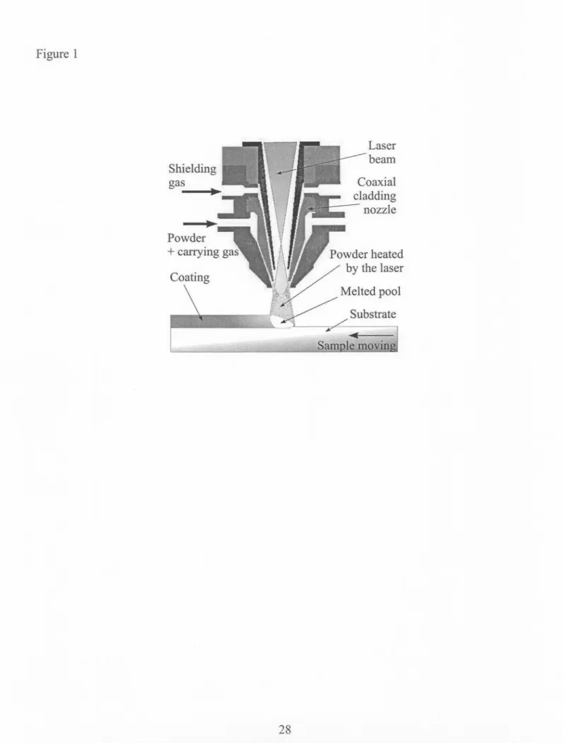
Aluminium alloys offer important advantages in term of their specific weight, corrosion resistance and thermal conductivity. However, they have poor tribological characteristics. This drawback can be corrected using laser surface treatment, which does not affect the global properties of the bulk material. In the case of aluminium alloys, two surface treatments have been thoroughly investigated: laser alloying and laser cladding. Laser alloying consists in melting the aluminium surface with a laser beam while added element. The resulting material is an alloy between the substrate aluminium and the adding element. This process can be carried out in different ways: pre-placed layer by electrolysis [1], application of a binder [2] or powder [3], or direct powder injection in the melted pool [4,5]. Laser cladding, studied in the present work, consists in covering the substrate surface with a coating of a different nature as illustrated in Fig. 1. This process can be carried out in different ways: wire feeder, powder injection by lateral nozzle [6] or coaxial nozzle [7] (See Fig. 1). The cladding powder is injected into the laser beam by an inert gas flow. The energy delivered by the laser is absorbed both by the powder jet and the substrate material. This enables the melting of the in-flight particles and the fusing of the powder onto the substrate surface. A clad is formed by moving the sample under the laser beam. An uniform layer is obtained by partly overlapping individual clads. A light dilution of the clad in the substrate surface generates a perfect metallurgical bonding between them. This method makes it possible to obtain homogeneous matrix microstructures and uniform carbide distribution in the coatings.
--,--Over the last fifteen years, many studies on aluminium laser surface treatment have been carried out with the objective of improving the mechanical characteristics of cladded coatings (hardness, elastic modulus, wear resistance). Several authors have already investigated the formation of intermetallic aluminium compounds (alloys AI-Ni [1, 3], AI-Fe [8], AI-Cu [9, 10], AI-Mo [11] and Al-Cr [12]) and the silicon precipitation in Al-Si alloys [13, 14]. Another field of study have consisted in the development of metal matrix composites (MMC) coatings. In laser surface treatment, these materials are composed of hard particles (reinforcement) distributed in a softer metal matrix. In case of aluminium treatment, the reinforcements most studied are silicon carbide [15] and titanium carbide [16]. In the present study, the influence of the silicon content in the coating matrix and TiC volume fraction on mechanical properties of the MMC coatings is investigated. Coatings are made from an aluminium matrix containing 0 to 40 wt.% Si and a TiC volume fraction ranging from 0 to 30 %. The laser cladding is carried out using a coaxial powder injection configuration (see Fig. 1). The coating microstructure is analysed by optical microscopy and XRD and sample mechanical properties are characterised by hardness and adhesive wear resistance.
2. Experimental set-up
2.1 Laser parameters and component set-up
Laser cladding was carried out using a 2000 W continuous wave Nd:YAG laser of 1.064-).lm wavelength and a I-mm diameter optical fiber. At this wavelength, the absorption coefficient of the aluminium substrate is about 25%, which is two times higher than that obtained with a COz laser at a wavelength of 10.6 ).lm[17]. A lens of 300-mm focal length focused the laser beam. The selected parameters were as follows. The laser power was adjusted to 1700 W on the workpiece surface with a spot diameter of 3 mm: the calculated laser power density is then 240 W.mm-Z. The angle between the laser beam and the surface sample was set at 85°. Normal incidence was not used to avoid the risk of beam reflection, which could damage the optical fibre or the laser cavity. Samples were placed on an X-Y numeric table. The sample translation velocity was adjusted from 7.10-3to 1.7.1O-zm.s-l depending on the coating composition. Laser treated specimens were circular to allow wear tests with a ball-on-disk-type device (see Fig. 2). Specimens of commercial aluminium composed of 99.5% Al were used; their size is 060 x 8 mm (see Fig. 2). Their surface was sand-papered with a 120-grit SiC paper and then cleaned with acetone prior to laser cladding. The energy coupling between the laser beam and the aluminium surface is increased by this surface preparation [18]. Premixed powders of pre-allied AI-Si with varying Si content and pure TiC (see Table 1) were injected inside the laser beam at a rate
ranging from 0.13 to 0.2 g.S-I. Argon at 1 bar pressure and 0.05 1.s-1flow rate was used as a carrymg gas.
2.2 Sample characterisation
Microstructure evolution was perfonned by optical microscopy after mechanical polishing (diamond with l-J..lmgrain size) and chemical etching using Keller's reagent. Phases were identified by X-ray diffraction using a Siemens D5000 diffractometer (Cu-Ka radiation). Vickers hardness measurements were perfonned with a load of 50 N on the coating surface after machining. A ball-on-disk-type tribometer was used for wear experiments under dry-sliding conditions. The laser coating was machined to obtain a flat surface of about 2 mm wide (Ra
=
6J..lm)and cleaned with acetone. A tungsten carbide ball (diameter of 6 mm, hardness of 1400 HVO.2
and load of 5 N) slided on the machined circular coating (Fig. 2) as the substrate was rotated. The tangential speed was 0.4 m.s-l and the sliding distance was fixed at 1600 m. The wear experiments were not carried out under a controlled atmosphere. Wear was characterised using the volume loss of the specimen and the observation of the wear scars. The volume loss was calculated from the coating density, which can be adequately estimated using the law of mixture between the matrix and the carbides [19], and on the measurements of the sample mass loss (measurement with an accuracy of:t 0.1 mg). This approximation was valid, as the carbides were not dissolved in the matrix and the coatings were not porous. Observation of wear scars was perfonned by microtopography and scanning electron microscopy (SEM). The mass variation of the WC ball was not measured. Microtopographic data of wear tracks were obtained by an extended field confocal microscope [20] (STIL's Micromesure station) with a vertical resolution
of 0.01 !-tmand lateral resolution of 2 !-tm.The topography was measured on a 5 x 3 mm2 surface, with a sampling step of 2 !-tmin the horizontal plan. The SEM used was a Phillips type XL30 with high vacuum.
3. Results
3.1 Microstructure analysis
Coatings were produced with premixed powders of aluminium alloys containing 0, 12,30 or 40 wt.% Si (matrix) and TiC particles (reinforcement) with volume fraction set at 0, 10 or 30%. Every coating produced was free of pore or cracks and showed a good metallurgical bonding with the substrate. Coating thickness and width were controlled by the laser scanning speed and the powder feed rate. The typical coating thickness was around 1.2 mm for 0 and 10 vol.% TiC and 0.9 mm for 30 vol.% TiC. All coatings showed a homogeneous carbide distribution, as shown in Fig. 3 for coatings composed of the Al 12Si matrix and 10 vol.% TiC (Fig 3.a) or 30 vol.% TiC (Fig 3.b). Moreover, these coatings were uniform: microstructure scale and type were similar through the entire coatings.
Depending on the silicon concentration, the microscopic structure of the matrix was either hypoeutectic (Si contents equal or lower than 12 wt.%) or hypereutectic (Si contents higher than 30 wt.%). Up to 12 wt.%Si, the microstructure was composed of intact TiC particles, white a-At primary dendrites and a dark Al/Si eutectic phase (see Fig. 4.a). At 12 wt.% Si, the single eutectic
microstructure predicted by the binary diagram was not observed. This phenomenon can be explained by the rapid solidification rate peculiar to the laser process. Under dynamic conditions, zones of phase existence can be modified and the eutectic composition shifted to the silicon side of the diagram in case of rapidly solidified Al-Si alloys [21]. Similar phenomenon can be observed on Al-Cu alloys carried out by laser surface treatments [10]. With Si contents higher than 30 wt.%, the microstructure consisted in intact TiC particles, primary angular Si crystals surrounded by a-At denditric halos and branched Al/Si eutectic adjacent to the Al halos (see Fig. 4.b). This is a non-equilibrium microstructure. This can be explained by the fast solidification rate occurring during laser processing as follows. The Si particles nucleate from the liquid by a heterogeneous mechanism, grow into the melt and reject the aluminium solvent. This mechanism creates a silicon poor zone surrounding the Si particles. During equilibrium solidification, this zone is enriched again in Si by diffusion from the near liquid. In case of laser surface treatment, the solidification is too rapid to allow this diffusion process to take place and, consequently, the local Al concentration becomes sufficient to nucleate a-At phase. This a-At phase appears as halos surrounding the Si particles, which stop their growth. Several authors have reported a similar phenomenon occurring during laser cladding of hypereutectic Al-Si alloys [14, 22]. As hypoeutectic matrix, this type of microstructure was not altered by the TiC concentration. Microscopic observations revealed no superficial dissolution of the carbides due to partial melting. Furthermore, XRD analysis did not show the presence of any A14C3aluminium carbides as previously observed by Lietchi et at. [15] in the AI-TiC laser cladding. As shown in Fig. 5, XRD analysis detected only the presence of AI, Si and TiC.
3.2 Hardness measurements
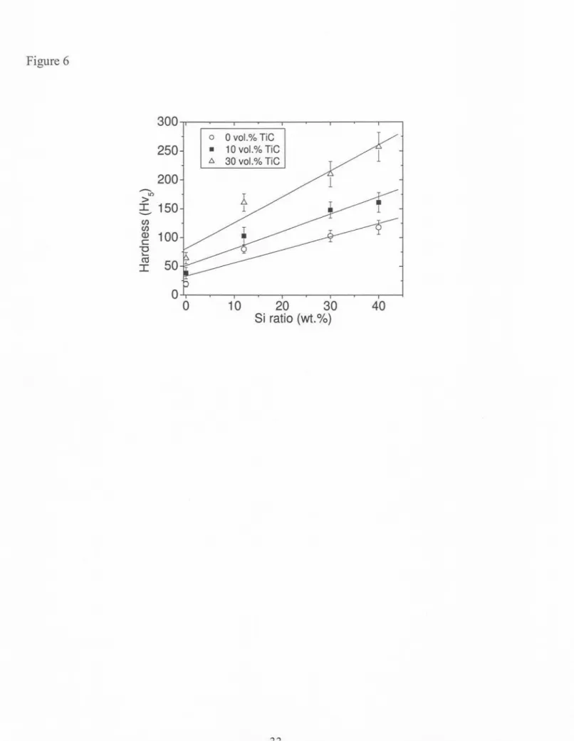
Fig. 6 shows the results of Vickers hardness measurements. Each value is an average of six measurements taken with a load of 50 N on the coating surface after machining. Loads lower than 10 N cannot be used for bulk hardness measurement owing to the large size (50-150 !-lm), dispersion and high hardness (3200 HV) of TiC particles. In order to characterise properly the hardness ofMMCs, the size of the indentation mark must be large in comparison with the size of the constituents. In such a condition, MMCs behave like a homogeneous material. Moreover, for all these measurements, the tip penetration was still 10 times lower than the coating thickness to avoid the substrate influence.
By increasing the Si ratio from 0 to 40 wt.% without carbide reinforcement, an increase of the micro-hardness from 19 :t2 to 118 :tlO HVs was observed. Fig. 6 indicates a linear correlation between hardness and Si ratio. For a given specimen without carbide reinforcement, hardness measurements were relatively independent of indentation position as expected for a relatively homogeneous microstructure. In the absence of carbide reinforcement, hardness improvement can be explained by:
(i) The shielding effect [23] due to the presence of Si phase in the case of the hypereutectic alloys (Si higher than 12 wt.%). In fact, these large (10-40 !-lm)and hard (hardness of around 1200 HVO.2[13]) phases create a metallic matrix composite (MMC) with the softer and finer eutectic/a-Al matrix. In consequence, during the load, elastic and plastic strains
I I I I I I I I
are incompatible between the Si reinforcements and the eutectic/a-A! matrix. This phenomenon reduces the load stress and increases the hardness.
(ii) The solution hardening of a-A! phase (supersaturation of a-A! primary dendrites) in case of hypoeutectic alloys (Si lower than 12 wt.%). The high quench rates, which can be attained by laser processing, cause an increased retention of Si in solid solution inside the
a-A! phases.
(iii) The structural refinement, corresponding to a reduction of the grain size due to rapid solidification rate [24].
As shown in Fig. 6, TiC reinforcement also increased the bulk hardness. This figure indicates a
I I I I I I I I I I I I
linear correlation for a fixed TiC concentration between the hardness and Si ratio. Compared with coatings that were not reinforced with TiC particles, the bulk hardness was increased by a factor of approximately 1.5 and 2.5 for 10 vol.% and 30 vol.% TiC addition, respectively. The maximum observed hardness of 250 HVs was reached with AI-40Si /30 vol.% TiC coating. This hardness improvement can be explained by the shielding effect [23] between the TiC particles and the AVSimatrix. TiC particles have a high hardness (2500 HVO,2[25]) and large size (50-150 ~m) compared with the microstructural features found in the Al/Si matrix. Consequently, their presence decreases the stress during the load due to the incompatibility of strains between these particles and the matrix, and increases the hardness.
3.3 Wear experiments
A ball-on-disk-type tribometer was used for the adhesive wear experiments with a sliding distance of 1600 m, a ball of WC and dry-sliding conditions. Wear was characterised using the volume loss of the specimen: Table 2 shows these results as a function of Si content of the Al/Si matrix and TiC ratio. The volume loss was calculated from the sample mass loss and the coating density (estimation via the law of mixture between the matrix and TiC densities [19]). This approximation was correct because the carbides did not dissolve in the matrix like discussed earlier (see Fig. 4).
3.3.1 Coatings without TiC reinforcement
Without TiC reinforcement, the increase of Si content improved the wear behaviour of the coatings: the wear rate was decreased from 35 to 0,73 10-3mm3.m-lfor a Si increase from 0 to 40
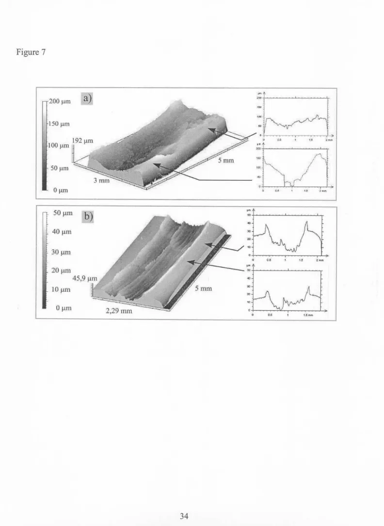
wt.% (see Table 2). In the case of hypoeutectic Al/Si alloys (AI and Al12Si coatings), wear tests led to a strong damage of the coating surface with material transfer from the sample to the ball. Plastic zones were noticed where the material is pushed leading to a wave type profile (see Fig. 7.a). After a sliding distance of 1600 m onto the Al l2Si coating, the wear track depth evolved from 50 to 150 /lm (see Fig. 7.a). In the case of pure aluminium coating, the test was stopped after a sliding distance of 400 m due to the excessive damage of the track, which caused the jumping of the ball on the surface. SEM observations revealed also many wear scars of large size: up to 2mm long and lmm wide (see Fig 8.a). These scars can be delaminated zones (spalling).
This wear mechanism can be associated with a "severe wear" as observed by Zhang and Alpas during wear experiments onto bulk aluminium-silicon alloys at high-applied loads [26]. According to these authors, severe wear involves massive surface damage, high wear rate and large scale material transfer to the counterface. All these conditions were observed on hypoeutectic Al/Si coatings without TiC reinforcement (AI and Al12Si coatings).
In the case of hypereutectic Al/Si alloys (AI 30Si and Al 40Si coatings), one noted a more homogeneous wear track and the formation of fine black debris. For the Al 40Si coating, for example, the wear track depth was around 20 /-Lmafter 1600 m sliding distance as shown in Fig 7.b). This type of damage was also characterised by the lack of strong delaminated zones (Fig. 8.b). Moreover, the wear rate was significantly lower than that observed with the hypoeutectic alloys as shown in the Table 2: for Al 40Si coating, the wear rate was 0,73.10-3 mm3.m-l compared with 7,6.10-3mm3.m-lin case of Al 12Si coating or 35.10-3mm3.m-lin case of pure Al coating. Actually, the wear rate was reduced by a factor ranging from 10 to 50. The same phenomenon was also noticed with the Al 30Si coating. This type of damage gathers the characteristics of a "mild wear" as observed by Zhang and Alpas during wear experiments onto bulk aluminium-silicon alloys at low-applied loads [26]. The transition from a severe to a mild wear may result from the bulk hardness increase as the Si content increases (observed earlier, see Fig. 6). This enhancement limits the plastic deformation of the coating and surface asperities. As more precisely discussed later (section 4), the plastic deformation of surface asperities plays an important role in the adhesive wear mechanism. In fact, asperities and wavy forms of the surface support the normal load from the ball. Consequently, for a rough surface, the stress level can be very high inducing plastic deformation of surface asperities. Then these asperities are in intimate
I I I I I I I I I I I I I
contact with the ball surface, promoting adhesion between the two surfaces in contact. These junctions are then broken and result in material transfer onto the mating surface or creation of
debris [27].
3.3.2 Coatings with TiC reinforcement
On hypoeutectic Al/Si coatings (AI and Al 12Si alloys), the same transition from severe wear to mild wear was observed as TiC ratio increases. As seen earlier, severe wear was observed on hypoeutectic Al/Si coatings without TiC reinforcement. On coatings based on Al or Al 12Si with 30 vol.% TiC, wear became homogeneous (Fig. 9.a and 1O.a),the wear rate was strongly reduced (Table 2), the track depth was regular (Fig. 9.a) and fine debris were formed. The type of damage was clearly mild wear and coincided with the TiC ratio increase. TiC addition strongly decreased the wear rate of the MMC coatings based on Al or Al 12Si matrices. In the case of AI 12Si matrix, the wear rate was 7,6.10-3mm3.m-Iwithout TiC carbide and 0,88.10-3mm3.m-Iwith 30 vol.% TiC, a factor 10 improvement (Table 2). For pure Al matrix, the improvement reached a factor of 20 with respective wear rates of 35.10-3and 1,8.10-3mm3.m-Ifor 0 and 30 vol.% TiC. However, zones where wear is more pronounced were observed on the surface: the track depth evolved from 10 to 20 /-lm(Fig. 9.a). This phenomenon can be explained by wear oscillating between mild and severe. The transition was not complete as in the case of Al40Si without TiC reinforcement (Fig. 7.a). Moreover, SEM observations also revealed some delaminations of fine size (100 /-lm)and small depth (10 /-lm)on the track surface (see Fig. 1O.a).
On the contrary, on hypereutectic alloys (AI 30Si and Al 40Si alloys), the TiC ratio increase had a damaging effect on the wear behaviour. For example, the wear rate was increased by a factor of 2 between 0 and 30 vol.% TiC with the coatings produced from Al40Si matrix (Table 2). Wear tracks were globally uniform and shallower (around 15 )..lmfor AI-40Si /30 vol.% TiC coating compared with 20 )..lmfor a AI-40Si coating without carbide) but important delamination appeared on the surface. These scars were easily observable by microtopography (Fig. 9.b) and SEM (Fig. 10.b and 10.c). On AI-40Si /30 vol.% TiC coating, the scars were approximately 10
I I I I I I
)..lmdeep, I mm long and 30 )..lmwide (Fig. 1O.b). Moreover, SEM observations revealed the fracture of many TiC particles as shown on the Fig 10.d. A similar but less pronounced phenomenon was noted on Al 30Si based MMC coatings. Consequently, the damage remained mainly of a mild wear type but early signs of surface fatigue were observed. The superficial stresses generated by the ball damage the surface and this favours a cyclic movement of pure sliding. The effect of the Hertz stresses caused subsurface fractures; these cracks grow up to the surface leading to the removal of the fractured fragments [27].
4. Discussion
4.1 Formation of aluminium carbide phase
Microscopic observations did not reveal any TiC superficial dissolution due to partial melting. This absence of dissolution was confirmed by XRD analysis (Fig. 5): the diffraction peaks did not
show the appearance of Al4C3aluminium carbides as observed by Lietchi et al. [15] in the AI-TiC laser cladding. Nevertheless, this observation should be completed by a more detailed study, as XRD measurement is only sensible to a phase volume fraction higher than 5% [28]. Moreover, Park and Lucas have proved that Al4C3carbides can precipitate like hexagonal platelets onto the reinforcement surface [29]. These platelets were 0,7 /lm thick and 3 /lm wide on the average. The small size of these platelets makes their detection by XRD or optical microscopy difficult. In any event, Al4C3carbide precipitation must be avoided as it results in:
(i) Degradation of mechanical properties due to the matrix strengthening [30]
(ii) Reduction of reinforcement/matrix interfacial strength and degradation of fracture behaviour of MMC due to the brittleness of the Al4C3 phases surrounding the TiC reinforcements [30]
(iii) Increase in corrosion sensitivity. Due to its hydrophilic nature, Al4C3is decomposed into aluminium hydroxide AI(OH)3 and methane C~ in moist environments. This promotes accelerated fatigue crack growth rates and reinforcement debonding in MMC [15].
Studies showed that the use of hypereutectic Al/Si matrix (Si higher than 30%) can inhibit the Al4C3precipitation in MMC laser cladding [15] or MMC powder metallurgy [31]. This is based on the principle that Si activity will be enhanced according to the amount of Si within the Al matrix. Since silicon is more carbide-forming than aluminium, SiC will precipitate preferentially over A14C3.However, as observed earlier in this study, the use of hypereutectic Al/Si matrix can decrease the adhesive wear resistance of MMC laser cladding. A possible way to increase the wear resistance is the addition of Ti instead of Si inside the matrix because Ti is more
carbide-forming than Al [32]. This way can lead to the in-situ precipitation of secondary TiC reinforcement instead of A14C3in the matrix or around the primary TiC particles.
4.2 Adhesive wear of MMC laser cladding
According to Deuis et al. [33], adhesive wear mechanisms on AI-based MMC can be summed up in 4 phenomena: (i) deformation of the material surface (classical theory), (ii) friction, (iii) tribolayer formation and (iv) delamination. According to the previous results, these phenomena can be also applied to the wear mechanisms observed on AI-based MMC laser cladding.
4.2.1 Deformation of the material surface
Deuis et al. explained that adhesive wear occurs when surfaces slide against each other and the pressure between the contacting asperities is high enough to cause local plastic deformation [33]. The hardness of the wearing surface determines then the real area of contact between asperities of both contacting materials. Asperity hardness is therefore considered to be more important than bulk hardness. In the present study, a linear correlation was noted between the TiC ratio and the bulk hardness. This enhancement can explain the wear track depth reduction as a function of TiC ratio (see Fig. 7.a and 9.a) since the plastic deformation (Ye) is linked to the hardness (H) according to the Eq. 1 [34]. A hardness increase causes therefore a bulk plastic deformation reduction, a wear track depth reduction and a transition from severe wear to mild wear.
Regarding surface asperities, SEM observations showed that almost the whole wear track was covered with the ductile Al/Si matrix (Fig. 10.a). The ball pushed the Al/Si matrix, which was more ductile than the TiC particles, until covering the reinforcements. Consequently, TiC reinforcements did not limit the local plastic deformation of surface asperities when wear is established. Nevertheless, TiC reinforcements can playa role during the first step of the wear process, i.e. when the wear track is not covered with the Al/Si matrix, or when the aluminium layer is removed (Fig. 10.b, 10.c and 10.d). TiC reinforcements are then in direct contact with the ball surface: adhesive phenomenon and wear are reduced as reinforcement asperities (2500 HV0,2
[25]) are less deformed than aluminium asperities (80 HVO,2for Al12Si matrix).
H=3Y
liEq. 1: Connection between plastic deformation (YJ of a material for an average strain E and hardness (H) for a metallic material.
If the coating elastic deformation is taken into account, the elastic modulus increase can also reduce the wear damage. According to Ashby [35], the bulk elastic modulus of a MMC alloy increases with the reinforcement ratio. Sallamand [36] and Lietchi [32] strengthen this phenomenon for AI-based MMC laser cladding with TiC and SiC reinforcements, respectively. Thereof, the elastic modulus increase with TiC ratio can limit the wear damage by reducing the sliding contact surface.
4.2.2 Fricdon
Friction is governed by 3 factors: (i) adhesion of flat regions of the sliding surfaces, (ii) ploughing by wear particles and hard asperities and (iii) deformation of the surface asperities [33]. Some studies showed that the adhesion decreases with hard particle ratio increasing in aluminium MMC materials [33]. Moreover, other studies also showed that ploughing decreases with hard particle ratio increasing in AI-based MMC materials [37]. These 2 phenomena reduce the friction, facilitate the ball sliding onto the coating surface and reduce the wear damage. The previous discussion showed that TiC reinforcement does not limit the deformation of the surface asperities. Consequently, this phenomenon may not playa significant role in friction mechanism.
4.2.3 Tribolayer formadon
For a mild wear, a tribolayer is created onto the track surface. This layer covering the whole wear track is mainly composed by the oxidised Al/Si matrix and fractured TiC debris. A closed SEM observation showed that many TiC reinforcements were cracked and fractured (Fig. 10.d). This brittle behaviour caused the formation of TiC debris that became encrusted again into the ductile Al/Si matrix. EDS analysis of this tribolayer showed also a high quantity of oxygen (around 20 at.%) compared with that in the as-deposited coating (oxygen content lower than 1 at.%). These EDS measurements were carried out on several coatings and wear zones. This may indicate that a certain volume of Ah03 was precipitated during the sliding and that an oxidation wear was possibly established. Like TiC debris, Ah03 oxide has high mechanical properties and high wear
resistance [33]. The simultaneous presence of TiC debris and Ab03 precipitates contributes to the protective properties of the tribolayer. On the other hand, tribolayer effects were limited during severe wear. High plastic deformations and large debris delaminations in the wear tracks contributed to the tribolayer disappearance. SEM observations showed the TiC debris onto the tribolayer but to a much lesser extent in mild wear. In the same way, EDS analysis confirmed this hypothesis by indicating a low oxygen content measured on the track surface (lower than I at.% and equal to the non-worn surface content). Ab03 oxide did not have time to grow before its destruction.
Use of hypereutectic AI/Si matrix in MMC cladding also destroyed the tribolayer. In this case, the tribolayer could not tough enough to resist the cyclic movement of the ball. Surface fatigue appeared with large delaminations in the tribolayer (Fig. 9.b, 10.b and 10.c). The tribo1ayer was then removed and TiC reinforcements were uncovered on the wear track. Due to the successive impacts of the WC ball, TiC reinforcements were then fractured and the wear rate increased. In case of hypoeutectic Al/Si MMC coatings, the tribolayer was ductile enough to limit the crack growth and the delamination. In fact, a ductile tribo1ayermust cover the AI-based MMC coatings in order to give an optimal resistance against adhesive wear.
4.2.4 Delamination mechanism
Delamination mechanism occurs in the following sequential steps [33]: (i) cyclic plastic deformation of surface layers by normal and tangential loads, (ii) crack nucleation in the deformed layers at inclusions or second-phase particles, (iii) crack growth nearly parallel to the
surface, (iv) formation of wear debris particles and removal by propagation of cracks to the surface. During severe wear, delamination mechanism is very pronounced. For example, scar size could reach 2 mm on coatings produced from Al or Al 12Si powders without TiC particles (Fig 8.a). During mild wear, delamination mechanism is strongly reduced. It only appears in the tribolayer that covered the wear track. Crack growth within the coating is limited by the TiC reinforcements under the tribolayer as shown in the Fig. 10.c. This reduces the size and thickness of the scars and, as a consequence, decreases the wear rate.
5. Conclusion
In this work, AI-based MMC laser cladding onto Al substrate was successfully carried out using a Nd:YAG laser and a coaxial powder injection system. Reinforcements were constituted of TiC particles (50-150 J.lIIl)in the range of 0 to 30 vol.%. The matrix was composed of aluminium with 0, 12,30 and 40 wt.% Si. After adjustment of the powder feed rate and scanning speed, coatings were free of pore and cracks. Coatings were very well bonded to the substrate. These are very important prerequisites for investigation of MMC mechanical behaviour. Depending on Si concentration, the matrix microstructure was hypoeutectic or hypereutectic. Carbides were uniformly distributed in the surface and appeared unaffected by the treatment. Complementary observations must be achieved to show the presence or the lack of A4C3 hexagonal platelets onto the TiC reinforcement surface. Si content and TiC reinforcement ratio increased the bulk coating hardness up to a maximum value of 250 HVs. This can be mainly explained by the shielding
effect between the Si phases and the AlISi matrix in coating without any TiC reinforcement and between TiC reinforcements and Al/Si Matrix in MMC coatings. For a fixed TiC ratio, a linear correlation was observed between hardness and Si content. The adhesive wear behaviour changed strongly with the Si and TiC ratios. Hypoeutectic alloys (Si ~ 12 wt.%) without TiC reinforcement showed a severe wear dominated by extensive plastic flow and significant wear scars. With the TiC addition, a mild wear was observed that is characterized by a low wear rate and a fine and homogenous damage. In the case of hypereutectic alloys (Si ~ 30%) without TiC reinforcement, wear was also mild and the wear rate was similar to the one observed on Al-12Si /30 vol.% TiC coating. Addition of TiC reinforcements accelerated the deterioration of these hypereutectic alloys due to the surface fatigue. The TiC reinforcement was harmful in hypereutectic Al/Si coatings. Combination of four phenomena can explain all wear mechanisms observed on the AI-based MMC coatings: deformation of the coating surface, friction, tribolayer formation and delamination. Laser cladding of MMC coatings onto aluminium substrate is a research field growing interest from automotive industry. MMC coated light materials can provide significant technology progress in direction of building light motors with improved efficiency. That is why understanding the influence of composition, hardness and microstructure on wear mechanisms is fundamental in order to obtain a fast advance in this field.
References
[2]: K. Uenishi, A. Sugimoto and K. Kobayashi, Z.Metallkd. 83 (1992) 4,241-245.
[3]: D. K. Das, K. S. Prasad and A. G. Paradkar, Mater. Sci. Eng. A174 (1994) 75-84.
[4]: F. Hlawka,G. Q. Song and A. Comet, Jour. Phy. IV, Vo16(1996), 123-126.
[5]: A. Almeida, M. Anjos and R. Vi1ar,Surf. Coat. Tech. 70 (1995) 221-229.
[6]: Y. Li, H. Yang, X. Lin, W. Huang, J. Li and Y. Zhou, Mater. Sci. Eng. A, vol. 360, nO 1-2
(2003) 18-25.
[7]: J. Lin and W. M. Steen, Jour Laser Appl., voLlO, n02 (1998) 55-63.
[8]: W. J. Tomlinson and A. S. Bransden, Jour. Mater. Sci. Let. 13 (1994) 1086-1088.
[9]: J.L de Mol Van Otterlo and J. Th. M. De Hosson, Proc. of the Computer Methods and Experimental Measurements for Surface Treatment Effect, Vo11, n01, (1995) 255-263.
[10]: L. Dubourg, H. Pelletier, D. Vaissiere, F. H1awka and A. Comet, Wear 253 (2002) 1077-1085.
[12]: Y. Y. Qui, A. Almeida and R.Vilar, Scrip. Metal. et Mater., Vol 33, n06 (1995) 863-870.
[13]: E. Blank, T. Liechti and L. Poin~,Proc. of 8thCIMTEC: Symposium on high performance materials in engine technology (1995) 203-208.
[14]: Y. T. Pei and J. Th. M. De Hosson, Acta Mater. (2000) 2671-2624.
I I I I I I I
[15]: T. Lietchi and E. Blank, Surface modification technologies VIII, Ed T.S.Sudarshan, TMS pub (1995) 421-427.
[16]: J.M. Pelletier, P. Sallamand and B. Criqui, Jour. Phy. IV, Vol. 4 (1994) 93-96.
[17]: J.e. Jules, J.M. Pelletier, M. Pilloz and A. B. Vannes, Jour. Phys. IV, Vol. 1 (1991) 61-63.
[18]: A. Ott, F. Dausinger and H. Hugel, Proc. of ICALEO 2000, Vol. Laser Materials Processing
(2000) 256-264.
[19]: M. F. Ashby, Jour. Phys. IV, Vol. 3 (1993) 1595-1600.
[20]: J. Cohen-Sabban, Mesure n0719 (1999) 85-90.
[22]: L. Dubourg, Developpement d'alliages de surface elabores sous faisceau laser sur substrat aluminium: application au rechargement de surface, PhD Thesis, University of Louis Pasteur, Strasbourg France (2002).
[23]: J. Phillibert, A. Vignes, Y. Brechet and P. Combrade, Metallurgie, Editions Masson (1998).
[24]: J. Th. M. De Hosson and J. Noordhuis, Jour. Phys. IV, Vol. 3 (1993) 927-932.
[25]: P. Tassot, Revue de metallurgie, 1 (1988) 81.
[26]: J. Zhang and A. T. A1pas,Acta Mater., Vo12, n02 (1997) 513-528.
[27]: K. G. Budinski, Surface engineering for wear resistance, Prentice hall, (1988) 30-38.
[28]: N. Broll, Techniques de l'Ingenieur, PE 1080 Vol. PE2 (1997).
[29]: J. K. Park and J. P. Lucas, Scrip. Mater. vol. 37 (1997) 511-516.
[30]: J. A. Vree1ing,V. Ocelik and J. Th. M. De Hosson, Scrip. Mater. Vol. 42 (2000) 589-595.
[32]: T. Lietchi, Developpement de revetements portants deposes par laser sur des alliages
d'aluminium, PhD thesis n01581, Federal Polytechnic School of Lausanne, Lausanne,
Switzerland (1996).
[33]: R. L. Deuis, C. Subramanian and J. M. Yellup, CompoSci. Tech. 57 (1997) 415-435.
[34]: A. Comet and J. P. Deville, Physique et Ingenierie des Surfaces, EDP Sciences, ISBN
2-86883-352-7 (1998) 102
[35]: M. F. Ashby, Jour. Phy. IV, C7 (1993) 1595-1600.
[36]: P. Sallamand, Alliages de surfaces et revetements elabores sous faisceau laser par projection de poudres sur substrat base aluminium, PhD thesis, Institut national des Sciences appliquees de Lyon, France (1994).
Figure captions
Figure 1: principle of laser cladding with coaxial powder injection.
Figure 2: Sample after laser cladding and prior machining.
Figure 3: (a) Cross section of AI-12Si 110 vo1.% TiC coating produced with a scanning speed of 1.3.10-2 m.s-l and powder feed rate of 0.13 g.S-l. (b) Cross section of AI-12Si/30 vo1.% TiC coating produced at a scanning speed of 1.7.10-2m.s-l and powder feed rate of 0.15 g.S-l
Figure 4: (a) Micrograph of AI-12Si 130 vo1.%TiC coating (b) Micrograph of AI-40Si 130vo1.% TiC coating.
Figure 5: XRD peaks (AI-12Si 130vo1.%TiC coating) indicating the presence of AI, Si and TiC.
Figure 6: Vickers hardness evolution vs. Si and TiC concentrations. Each value is an average of six measurements taken with a load of 50 N on the coating surface after machining.
Figure 7: Microtopographies and transverse sections of wear tracks after the 1600-m sliding test on: a) a coating performed from Al 12Si, b) a coating performed from A140Si.
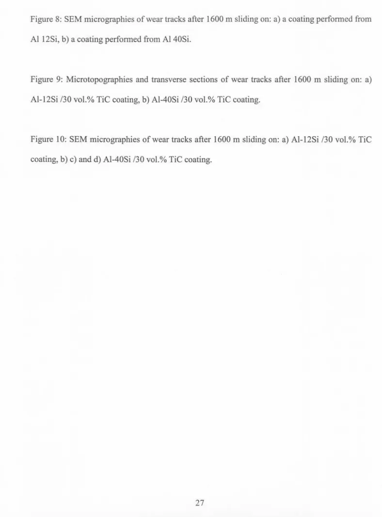
Figure 8: SEM micrographies of wear tracks after 1600 m sliding on: a) a coating performed from Al 12Si, b) a coating performed from Al 40Si.
Figure 9: Microtopographies and transverse sections of wear tracks after 1600 m sliding on: a) AI-12Si /30 vol.% TiC coating, b) AI-40Si /30 vol.% TiC coating.
Figure 10: SEM micrographies of wear tracks after 1600 m sliding on: a) AI-12Si /30 vol.% TiC coating, b) c) and d) AI-40Si /30 vol.% TiC coating.
Figure 1 Shielding gas Laser beam Coaxial cladding nozzle Coating Powder heated by the laser Melted pool
..-_...
-- - - - ---
---Figure 4
a-AI
eutectic
TiC
TiC
(Si)
I
I
I
I
I
I
0 lntensite (U.A.) tV 0 0 0 0 0 0 v.> 0 0 0 tV 0 .j:. 0 W tV tV c:D0\ '60 '-' 00 0 ... 0 0 >-rj ~. >; CD VI Si TiC (Al,Si) TiC -Si (Al,Si) :>-Si TiC (Al,Si) Si =---TiC c-Si (Al,Si) >-(Al,Si) Si TiC (Al,Si) -TiC ?-TiC
Figure 6 300 I I 0 0 vol.%TiC 250
I.
10vol.%TiCI
/1
f::. 30 vol.%TiC -1 200-£
In 150J 1. 1 -en en Q) 100 c:: u.... (\j 50 LL I 0 0 10 20 30 40 Si ratio(wt.%)Figure 7 100 f.lm 50 ~tm " Of.lill 50 JlIll 40 JlIll 3o..~ z~~ lOJl,Ill 0 ~lln 2,29 Illm
~---.-- ---Figure8 I I I I I I I I I 35
Figure9 50~111 40f..t111 '"
g
'"
,.
"
"
r'-", ¥~
~
g
" ,'~
0"
,
"'
,
'
",
'~.'-" . ',"'' . .,-' . ' ' ."'.,, .,,~~ .. .. " ", "'~V\ J " \,,/V 'h. ' , " ," " ---Figure 10 --- - - ---I I I I I
I I I I I I
Tables
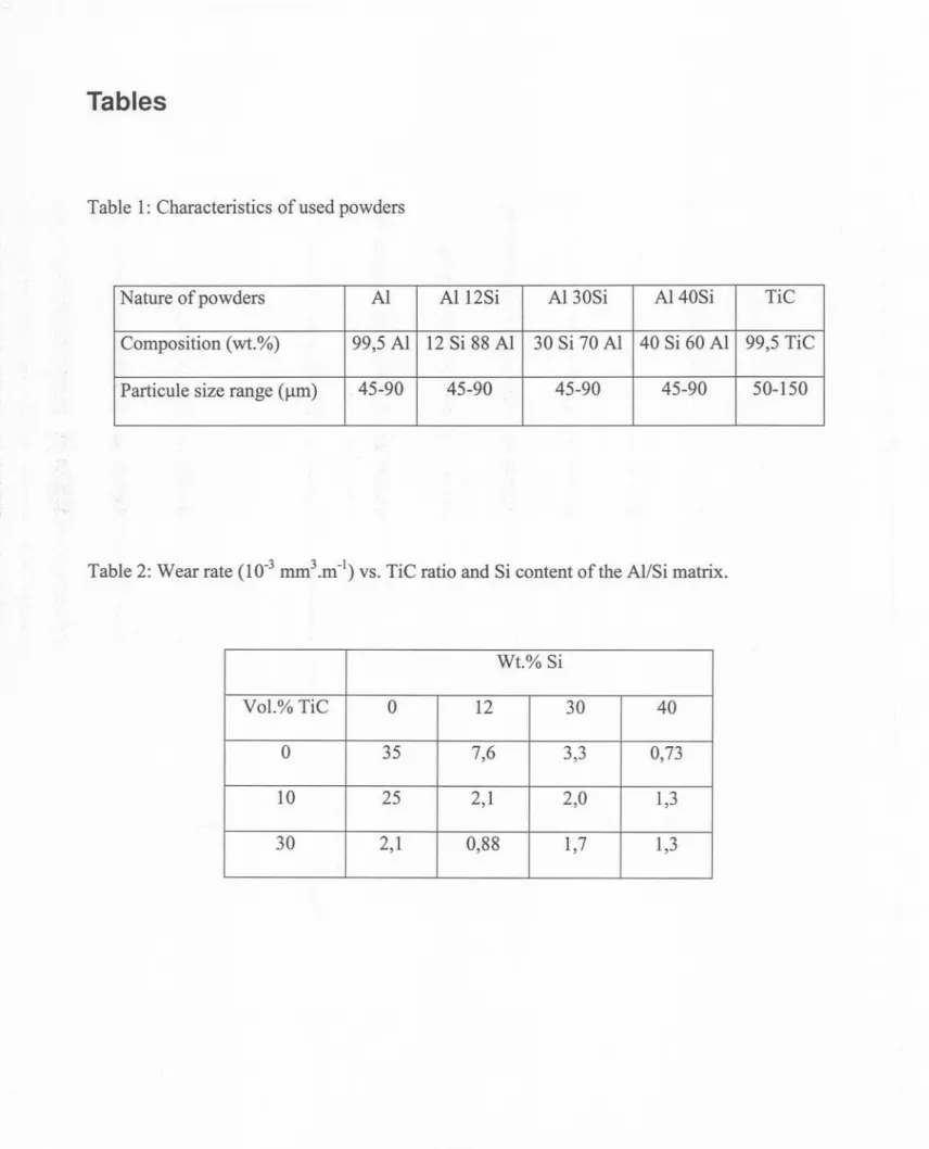
Table 1: Characteristics of used powders
I I I I' I I I I I I
Table 2: Wear rate (10-3mm3.m-I)vs. TiC ratio and Si content of the Al/Si matrix.
Nature of powders Al AII2Si Al 30Si Al 40Si TiC
Composition (wt.%) 99,5 Al 12 Si 88 Al 30 Si 70 Al 40 Si 60 Al 99,5 TiC
Particule size range (f..lm) 45-90 45-90 45-90 45-90 50-150
Wt.% Si
Vol.% TiC 0 12 30 40
0 35 7,6 3,3 0,73
10 25 2,1 2,0 1,3