Candidate Anode Materials for Iron Production
by Molten Oxide Electrolysis
by
James D. Paramore B.S. Metallurgical Engineering
University of Utah, 2007
Submitted to the Department of Materials Science and Engineering in Partial Fulfillment of the Requirements for the Degree of
Master of Science in Materials Science and Engineering at the
Massachusetts Institute of Technology September 2010
02010 Massachusetts Institute of Technology. All rights reserved.
MASSACHUSETTS INSTITUTE OF TECH)OLOGY
NOV
19
2010
MBR IES
ARCHIVES
I
->
Signature of Author: Certified by: 'IDepartment of Materials Science and Engineering August 13, 2010
A
Donald R. Sadoway John F. lliot Professor of Materials Chemistry Thesis Supervisor
(V
Accepted by:
Christopher Schuh Chair, Departmental Committee on Graduate Students
Z-110
\
\Candidate Anode Materials for Iron Production
by Molten Oxide Electrolysis
byJames D. Paramore
Submitted to the Department of Materials Science and Engineering on August 13, 2010 in Partial Fulfillment of the
Requirements for the Degree of Master of Science in Materials Science and Engineering
ABSTRACT
Molten oxide electrolysis (MOE) has been identified by the American Iron and Steel Institute (AISI) as one of four possible breakthrough technologies to alleviate the environmental impact of iron and steel production. This process has also been identified by the National Aeronautics and Space Administration (NASA) as a means to produce oxygen gas, as well as iron and silicon raw materials on the Moon. MOE produces iron by electrolysis of an iron oxide containing electrolyte. The electrolysis results in the production of pure iron metal at the cathode and pure oxygen gas at the anode. Because of the low vapor pressure of the electrolyte at temperatures above 1538*C, MOE can be performed above the melting temperature of iron. The production of liquid metal, ready for continuous casting, is a prerequisite for any industrial-scale extractive metallurgical process. Therefore, if an inert anode can be identified, MOE could provide a an industrial process to produce iron from its ore with pure oxygen gas as the only direct emission. The feasibility of MOE as a carbon-neutral process hinges on the identification of an inert anode material. Therefore, the scope of this study was to determine the criteria of an inert anode for MOE, identify candidate materials, and evaluate the performance of these materials. Previous studies of MOE at MIT found iridium, a platinum group metal, to be an excellent candidate for an inert anode. The high cost of iridium makes it an unlikely candidate for a commercial iron production process. However, iridium provides a likely candidate for lunar production of oxygen, or high-purity iron production. Furthermore, the use of iridium on the laboratory-scale provides a widely available inert anode material to facilitate the study of other areas of MOE. Therefore, unique anode morphologies were evaluated as a means to reduce the economical strain of using an iridium anode.
In addition to iridium, a wide array of readily available, high-temperature electrode materials were tested. Due to the highly corrosive environment of MOE, none of the readily available materials tested are compatible with the process. It is believed that the most likely candidate for an inert anode lies in an engineered material, composed of a refractory substrate and an oxide passivation layer. Therefore, the criteria for such a material were determined and likely candidates are discussed.
Thesis Supervisor: Donald R. Sadoway
BIOGRAPHICAL NOTE
James D. Paramore was born and raised in Salt Lake City, Utah. During his undergraduate education at the University of Utah, James had the opportunity to participate in research of various metallurgical fields including electrowinning of copper, room-temperature electrolysis of titanium, and production of bulk-nanocrystalline refractory materials. His most extensive undergraduate research opportunity was enjoyed during his last three years as an undergraduate, in which he helped develop a new powder metallurgical process to produce bulk nanocrystalline refractory materials under the supervision of Professor Z. Zak Fang. Professor Fang is a truly extraordinary mentor, affording James trust and responsibility that accelerated his scientific maturation. James was Professor Fang's primary researcher on a grant to research the production of nanocrystalline tungsten penetrators for the Army Research Laboratory (ARL). Professor Fang allowed James to attend and present at several technical conferences, as well as prepare and present quarterly updates to ARL. In addition to his research responsibilities, James also served as a teaching assistant for Introduction to Physical Metallurgy at the University of Utah.
James received several scholarships and awards as an undergraduate including the 2008 Materials Processing & Manufacturing Division Scholarship from TMS, 2007 Lucille & Charles A. Wert Scholarship from ASM, 2007 Kennecott Scholarship, 2007 Rio Tinto Scholarship, 2006 George A. Roberts Scholarship from ASM, and the 2006 Oblad Energy Scholarship, among others. James graduated magna cum laude from the Department of Metallurgical Engineering at the University of Utah. Upon arrival at MIT in Fall 2008, James was first introduced to Professor Donald Sadoway as a teaching assistant for 3.091: Introduction to Solid-State
Chemistry. In Spring 2009, James continued as the 3.091 teaching assistant under Professor
David Paul before joining Professor Sadoway's research group on the molten oxide electrolysis project in Summer 2009. Professor Sadoway has been an extraordinary mentor and inspiration to James, and has been a huge influence in James' life ever since.
In addition to his academic endeavors, James is a passionate musician. In fact, James started off his undergraduate education as a music major in piano, before deciding that music better suited him as a hobby, rather than a career. However, James worked as a professional club DJ in Utah during his undergraduate education, and performed at various music festivals as a keyboardist.
PREVIOUS PUBLICATIONS
J. Paramore, Z. Fang, H. Zhang, X. Wang, D. Siddle & K. Cho, "Production of Nanocrystalline Tungsten Using Ultra-High-Pressure Rapid Hot Consolidation (UPRC)." Advances in Powder Metallurgy and Particulate Materials, 2 (2007)
A. Shchetkovskiy, T. McKechnie, D. R. Sadoway, J. Paramore & 0. Melendez, "Development and Testing of High Surface Area Iridium Anodes for Molten Oxide Electrolysis." Proceedings ofEarth and Space 2010, 4 1039 (2010)
PENDING PUBLICATIONS
H. Kim, J. Paramore, A. Allanore, D.R. Sadoway, " Stability of Iridium Anode in Molten Oxide Electrolysis for Ironmaking: Influence of Slag Basicity." ECS Transactions, 29 (2010)
ACKNOWLEDGEMENTS
I thank the American Iron and Steel Institute (AISI) and the National Aeronautics and Space Administration (NASA) for their financial sponsorship.
I would like to thank each of the following individuals and groups who have aided in the completion of this thesis:
Professor Sadoway, for seeing potential in me, always fighting on my side, and for all his words of inspiration which helped me through some doubtful times. He is a true lifelong friend and mentor.
Dr. Hojong Kim, for all his kind help and long hours spent with me in the lab, and for his constant readiness to sit down with me and talk about the often confusing results from our experiments.
Dr. Antoine Allanore, for all of his hard work on the MOE project and his seemingly endless ambition to tackle the problems we faced, as well as his constant honesty about my results. Mr. Mike Tarkanian, for spending hours upon hours training me on all the machining equipment in our department, as well as coming at a moment's notice to help me fix a machine that broke. Mr. Guenter Arndt, for always being ready, willing, and happy to help pursue whatever tedious work I would bring him.
Ms. Hilary Sheldon, for always having the answer to administrative questions and saving my rear-end on more than one occasion.
Everybody in the Sadoway research group, whose camaraderie and kindness made it a pleasure to come to work everyday, and for always being willing to lend a hand whenever possible. Ms. Anna Henry, for moving with me 2500 miles aways from her friends and family, and for helping me through the stress and frustration that comes with graduate studies.
I dedicate this thesis to my parents, Ray and Nancy Paramore, who I know have been on an emotional roller-coaster ride throughout my upbringing. I was a hard pill to swallow at times, but they always put immeasurable trust and confidence in my abilities, and supported me all along the way. I know that, regardless of circumstance, they will make the greatest of sacrifice if there is even the slightest chance that it will positively affect my wellbeing, and for that I am truly grateful.
My time at MIT has been a mixture of tribulations and celebrations. While I leave this extraordinary institution with a vast knowledge of science and engineering, I have also been taught valuable lessons on humanity and social responsibility; things which are often lost in the abstractions of science. I will dedicate my life to continuing these awesome traditions and strive to be a worthy progeny of my mentors.
Table of Contents
Chapter 1: Introduction...7
1.1 M otivation...7
1.1.1 Iron Production... 7
1.1.2 Lunar Production of Oxygen... 8
1.2 Fundam ental M OE Considerations... 9
1.2.1 Basic Cell Design... 10
1.2.2 Inert Anode Criteria... 11
1.2.2.1 Platinum Group M etals...12
1.2.2.2 Oxide Passivated M etallic Anodes... 13
1.2.2.3 Cerm et Anodes... 15
1.2.3 Electrolyte Criteria... 15
1.2.3.1 Optical Basicity ... 16
1.3 Sum m ary...18
Chapter 2: Experim ental D esign... 21
2.1 Cell Design...21
2.1.1 Furnace A ssem bly... 21
2.1.1.1 D esign Im provem ents...23
2.1.2 M aterials Candidates... 25
2.1.2.1 Anode...26
2.1.2.1.1 Iridium Anodes... 26
2.1.2.1.1.1 Unique M orphologies...27
2.1.2.1.2 Other Anode M aterials... 28
2.1.2.2 Cathode...29
2.1.2.3 Crucibles...30
2.1.2.3.1 Effect of Electrolyte Basicity on Crucible Selection... 30
2.1.2.3.2 Novel Crucible Design ... 31
2.2 Electrolyte Selection... 33
Chapter 3: Experim ental Results... 35
3.1 Iridium ... 35
3.1.1 Electrodeposited Iridium Anodes...35
3.1.2 Effect of Electrolyte Basicity on Iridium Anodes...38
3.1.3 Results from N ovel Crucible Design...42
3.2 Other Candidate Anode M aterials... 44
Chapter 4: Implications of Experimental Results and Future Considerations... 47
4.1 Proposed Corrosion M echanism for Iridium Anodes...47
4.1.1 Suggested Experimentation to Quantify Corrosion Rate of Iridium...51
4.2 Anodes w ith Different Corrosion M echanism s... 53
4.3 Cold-W all Cells for the N ext Scale... 57
Chapter 5: Concluding Rem arks... 59
Chapter 1: Introduction
1.1 Motivation
Molten oxide electrolysis (MOE) uses electric current to reduce the metallic cation of an oxide to its pure form, while oxidizing the corresponding oxide anions into oxygen gas. Therefore, the study of this process has been motivated by the acquisition and use of these two products. The production of iron metal from an iron oxide containing electrolyte has been studied as a carbon-neutral approach to replace current pyrometallurgical processes that result in copious amounts of greenhouse gas emissions. Furthermore, the production of oxygen gas at the anode has been studied as a means to produce oxygen on the surface of the moon. While stemming from the same fundamental reaction, these two goals present unique challenges and feasibility criteria.
1.1.1 Iron Production
Iron is by far the most widely used metal. The majority of iron produced from ore is still achieved using antiquated blast furnace technology; which produces nearly 2 metric tons of carbon dioxide per metric ton of crude iron produced [1]. Furthermore, the vast majority of steel produced today is accomplished with a limited number of processes and nearly identical raw materials [1]. In terms of cost and efficiency, there has been little need for improvement of these highly efficient technologies over the centuries. However, despite the economical attractiveness, the environmental impact is substantial. In addition to carbon emissions from blast furnaces, the iron and steel industry contributes to greenhouse gas (GHG) emissions in several ways. Sources of GHG emissions form the iron and steel industry include: blast furnace emissions, coke production emissions, use of carbonate flux during calcination, and emissions from carbon electrodes in electric arc furnaces [2].
The iron and steel industry is currently responsible for 3-4% of the total worldwide greenhouse gas emissions [3]. In 2006, iron and steel mills produced 126 million metric tons of carbon dioxide [4]. While there have been myriad improvements to the intricacies of modern steelmaking since its introduction during the industrial revolution, nearly all crude iron
production today is accomplished using the same fundamental carbothermic processes. As a primary contributor of global GHG emissions from the industrial sector, the iron and steel industry has been under constant scrutiny from various national and international environmental associations such the U.S. EPA, the EIA, and IEA [1;2;4;5]. There have been great strides made by iron and steel mills to reduce GHG emissions through innovations made on legacy technologies. However, in order to realize a truly efficient, carbon-neutral technology, a radically different technology using fundamentally different extractive metallurgy is required.
Upon the use of an inert anode, molten oxide electrolysis (MOE) is theoretically capable of producing tonnage metal with oxygen gas as the only direct emission. Compared to other electrochemical extractive techniques, molten oxide electrolysis has several advantages including:
* Minimal pretreatment of the oxide ore feedstock is required
- The molten oxide electrolyte has low vapor pressure above 1538*C - Iron produced at the cathode is molten and ready for continuous casting
Some of the primary criteria for developing a commercial MOE process to produce iron and steel are economical considerations. With regards to industrial applications, this becomes a major factor. However, because MOE directly reduces iron oxide to iron metal, if carbon-free iron oxide feedstock is used, the product of MOE is high-purity iron metal. High-purity iron is currently an extremely expensive commodity in relation to steel, due to the elaborate processing required to remove the highly soluble carbon from carbothermically reduced crude iron [6]. Therefore, if MOE fails to develop into an economically feasible process for steelmaking, it could still be a viable one-pot alternative for the niche market of high-purity iron.
1.1.2 Lunar Production of Oxygen
The cost of transporting materials to the moon is approximately 100,000 USD per kilogram [7]. Nearly all of this cost is associated with the energy requirements to escape Earth's gravity.
Therefore, the feasibility of sending manned missions beyond the moon relies on the ability to launch missions from the Moon's considerably weaker gravitational hold. Considering that a large portion of the payload for any mission will be oxygen as an essential raw material for rocket fuel, as well as human life support, the ability to produce oxygen on the surface of the moon is a necessary prerequisite for future deep space exploration. The surface of the Moon is covered with a layer of regolith, which is a loose, rocky mixture of metal oxides (Table 1.1). Therefore, using lunar regolith as the feedstock for a MOE cell, future lunar missions would be equipped with the ability to not only produce oxygen, but also produce iron and silicon as raw materials for a lunar base.
Table 1.1: Approximate composition of lunar regolith.
Chemical Wt% SiO2 47.3 A1203 17.8 CaO 11.5 FeO 10.5 Fe2O3 0 MgO 9.2 Na2O 2.7 TiO2 1.6 K20 0.8 P205 0.7 MnO 0.1
1.2 Fundamental MOE Considerations
Previous work done at MIT has successfully addressed the fundamental electrochemistry of MOE [7;8]. Therefore, this study focuses primarily on the feasibility and engineering challenges associated with scale-up of the MOE process. The piece de resistance is, without doubt, the attainment of an inert anode material. However, other materials challenges must be addressed for the progressive scale-up steps on the road to commercial MOE. Optical basicity of the electrolyte and current density are the metrics used in this study to determine feasibility of electrode and crucible materials for the process' scale-up.
1.2.1 Basic Cell Design
The Hall-Heroult cell used in the aluminum industry may be studied as a basic representation for the MOE process (Figure 1.1). However, the MOE process presents several unique materials challenges:
- Extremely high operating temperatures (>1538 *C) expedite corrosion reactions - Strong oxidizing environment due to evolution of pure oxygen and anodic potential - Metal solubilizing liquid metal product
- Ceramic solubilizing molten oxide electrolyte
Therefore, in order to overcome these challenges, an industrially feasible cell must have the following characteristics.
- Inert anode capable of resisting the highly corrosive environment
- Thermal gradient to allow molten electrolyte to freeze at the extremities of the cell, therefore, protecting the refractories used to contain the bath
Similar to a Hall-Heroult cell, an MOE cell will use joule heating to maintain operating temperatures (>1538'C for an MOE cell), circumventing the need for fossil fuel heating.
Previous studies have demonstrated the fundamental feasibility of the process by showing successful electrolysis of molten oxide electrolytes [7;8]. Current efficiencies, when measured with respect to oxygen generation, varied between 30 - 60% during electrolysis in iron-containing electrolytes, and between 60 - 100% in iron-free electrolytes [7]. The discrepancy in current efficiency measurements with respect to the presence of iron is believed to be the result of two phenomena: aliovalent cycling between ferrous and ferric ions, and electrolytic short-circuiting caused by electronic conductivity of iron oxides [7].
current feed point feeders break
crust and introduce metal oxide here
efrozen
electrolyte Net anodic reaction:
anode oxygen gas 202- ->
02(g)+4e-frozen bubbles
electrolyte
molten oxide electrolyte liquid
cell shell cthode Net cathodic reaction:
sidewall metal
cell floor Fe"* + ne- > Fe (I)
collector bar
Figure 1.1: Theoretical schematic of an industrial MOE cell [8].
1.2.2 Inert Anode Criteria
The ability for MOE to be a truly carbon-neutral method for producing iron relies on the identification of a suitable inert anode material. The aluminum electrowinning industry uses carbon anodes in the Hall-Hdroult cell, which participate in the anodic reaction and evolve carbon dioxide gas. Therefore, the acquisition of an inert anode will have the greatest implication as to whether or not MOE is a viable, carbon-neutral process for iron production. The aluminum industry has put great effort into the search for an inert anode. As the Hall-Heroult cell is the nearest industrial equivalent to MOE, the MOE criteria for an inert anode have been adapted from the criteria used by the aluminum electrowinning industry:
1. Less 10 mm/year linear loss of anode material [9] 2. Physically stable above 1538*C [10]
3. Resistant to attack by molten oxide electrolyte [10]
5. Resistant to anodic (oxidizing) polarization [10]
6. Electronically conductive [10]
7. Resistant to thermal shock from lowering into molten oxide bath [10]
8. Mechanically robust [10]
9. Simple to deploy during startup and in case of power interruptions [10]
10. Economically feasible and widely available to meet the demands of the iron and steel
industry
With the above criteria in mind, the possible materials candidates are discussed below.
1.2.2.1 Platinum Group Metals
The platinum group metals (PGM) are widely used in the glass industry due to their excellent corrosion resistance in molten oxide glasses [11]. All of the platinum group metals, with the exception of ruthenium, are very expensive and are, therefore, ruled out as a pure anode material for steelmaking by criterion number 10 listed above. However, PGMs may be viable candidates for high-purity iron making (refer to last paragraph of section 1.1.1) and lunar production of oxygen; even in these applications it is likely the PGM will be in the form of a thin coating or as a small-concentration constituent in an alloy. Despite their unlikely transition to an industrial-scale option, PGMs have shown to be promising inert anode candidates, and provide long-lasting, readily available anode materials for laboratory-scale studies. Therefore, while use of PGMs for commercial steel production is prohibited by cost, these materials are very valuable to use as anodes during studies of other areas of the MOE process. Table 1.2 provides a list of the six PGMs and their advantages and disadvantages with respect to MOE.
Ruthenium, palladium, and osmium each have at least one property that is unavoidably incompatible with operating conditions of an MOE cell. Therefore, these metals were ruled out and investigation was never pursued. Previous work at MIT with the three remaining PGMs found iridium to be the most likely candidate as an inert anode material [8].
Table 1.2: Advantages of disadvantages ofplatinum group metals in regard to MOE.
Metal Advantages Disadvantages
Ruthenium Inexpensive PGM -$6/g Volatile at high temperatures in 02
[12]
Rhodium N/A Extremely high cost -71/g
Palladium N/A Melting temperature too low
Cost M 16/g
Osmum N/A Volatile at high temperatures in 02
[12] Cost ~$12/g
Iridium Most noble metal High hardness -- difficult to machine
Melting temperature = 2446'C Cost -$23/g
Resistant to molten oxides
Platinum Very noble metal Cost -$50/g
Resistant to molten oxides Melting temperature = 17680C
1.2.2.2 Oxide Passivated Metallic Anodes
An oxide passivated anode will likely be the best inert anode material if a suitable alloy can be found. The idea behind protective oxide layers was first described by Pilling and Bedworth in 1923 [13], and is utilized ubiquitously in corrosion resistance today. This phenomenon is when a metallic substrate, normally vulnerable to corrosion, is protected by an oxide layer which separates the metal from the environment. The oxide layer can either be grown on the substrate using an oxidizing environment or anodic potential, or physically placed on the substrate using sputtering, chemical vapor deposition or colloidal deposition [14]. In the case of MOE, it is likely that a system of two main components will be engineered: a refractory metal substrate alloyed with a reactive solute metal. If the solute metal is sufficiently reactive, it should preferentially oxidize to form the protective oxide layer.
The Pilling-Bedworth ratio (RpB) is a first approximation used to determine if an oxide will protect a metallic substrate. The ratio is calculated by dividing the molar volume of the oxide by the molar volume of the substrate metal [13]. If the ratio is much larger than 1, the oxide will tend to buckle and chip, causing the underlying metal to be exposed [13]. If the ratio is much smaller than 1, the oxide will not sufficiently cover the substrate, thereby allowing it to corrode [13]. There are many exceptions to this simple rule. However, this is the underlying theory of an oxide passivated inert anode. In order for an oxide passivated anode to work, there are
several criteria for the oxide layer, in addition to RPB~ 1, that must be met:
1. Electronically conductive to allow electrons to pass into the anode during the oxide ion oxidation reaction
2. Not conductive to oxide ions, as this would allow unmitigated growth of the oxide layer at the metal/oxide interface
3. Not conductive to either the solvent or solute cations, as this would allow consumption of the substrate or unmitigated growth of the oxide layer at the oxide/electrolyte interface, respectively
4. Not soluble in the multi-component molten oxide electrolyte
The oxide passivated anode has several key advantages over other possible candidates. The metallic substrate provides the bulk mechanical properties of the anodes, giving it the desired thermal shock resistance, toughness, and ease of machinability characteristic of metals. The metallic substrate will also have excellent electronic conduction. However, while the oxide layer protects the underlying substrate from corrosion, it also passivates the electric current. Therefore, in order to allow the necessary faradaic processes to occur at the surface of the anode, the oxide layer will have to support some form of electronic conduction.
Most oxides have large band gaps, resulting in poor electronic conduction. However, at MOE operating temperatures (>1538'C), some oxides exhibit semiconduction due to the high degree of thermal excitation. Therefore, use of one of these oxides should facilitate electronic transfer across the oxide passivation layer.
If an oxide is selected that exhibits no form of electronic conduction, the oxide layer will need to be thin enough to allow for electron tunneling. Generally, electron transfer rate, k4, decreases exponentially with the distance of tunneling, x, by the following equation:
k (x)=k0(x=0)exp (-3x)
(1)
for effective tunneling, the oxide must be extremely thin (x<1.5nm), and even thinner in the case of highly resistive oxides, such as those of aluminum and tantalum [14].
1.2.2.3 Cermet Anodes
A cermet is a metal/ceramic composite. Cermets, like any composite, are engineered to combine positive attributes of the two phases. With respect to inert anodes, this would be the corrosion resistance of the ceramic and the electronic conductivity and toughness of the metal [10]. Cermet anodes consisting of a ceramic matrix with metallic dispersions have been researched by the aluminum industry with varying results [10]. For example, success has been enjoyed in laboratory-scale aluminum electrowinning cells with cermet anodes, such as copper/nickel impregnated nickel-ferrite [15]. However, despite promising performance at the small scale, the poor thermal shock resistance of the ceramic matrix caused catastrophic failure of the anodes
upon lowering into the cryolite bath during pilot-scale tests [16].
It is unlikely that a cermet with a ceramic matrix will ever have the necessary thermal shock resistance to serve as an anode in an MOE cell. However, if a metal was found with corrosion resistance that was on the borderline of the inertness criterion, then a cermet could be engineered with that metal as the matrix with a ceramic dispersion. The ceramic dispersion would give the metal the small boost in corrosion resistance it needed to qualify as an inert anode. The theory behind such a cermet is that the ceramic dispersion would lower the active surface area of the metal exposed to the electrolyte. Therefore, the dispersion should reduce the corrosion kinetics of the metal, but the metallic matrix should impart the attractive mechanical properties of the metal to the cermet.
1.2.3 Electrolyte Criteria
The chemistry of the electrolyte greatly influences process parameters and materials compatibility issues. For the lunar project, the nominal electrolyte chemistry is set by the composition of the mandatory feed material, lunar regolith (approximate average composition of
lunar regolith is listed in Table 1.1). However, for the iron project, the electrolyte may be engineered. The following criteria must be kept in mind while determining the appropriate
electrolyte chemistry:
1. Melting temperature below 1538*C to limit heating power needs 2. Low vapor pressure of above 1538*C
3. Minimum viscosity at operating temperatures to facilitate fast oxygen bubble escape 4. Minimum possible electronic conductivity (to maximize current efficiency)
5. Maximum possible ionic conductivity
6. Minimum corrosiveness towards electrodes and refractories'
The complexity of multi-component oxide systems makes quantifying the physical properties of these systems extremely difficult. Therefore, considerations of criteria 1-4 were explored by painstaking study of multi-component oxide system phase diagrams, as well as literature on well known oxide slags used in the steel and glass industry [17; 18]. However, the ionic conductivity and solubilizing strength of molten oxides both tend to vary as a function of the slag's basicity. Therefore, a more quantitative approach was applied to criteria 5 and 6 by using the electrolyte's basicity as a metric.
1.2.3.1 Optical Basicity
There are important implications for the properties of a molten oxide that may be drawn from the slag's basicity (i.e. ionic conductivity, solubilizing strength, and redox equilibria of aliovalent species within the melt). Similar to aqueous systems, molten oxide systems tend to exhibit either a more acidic or more basic nature. The Lux-Flood formalism is used to define the acidic/basic nature of an oxide by evaluating the oxide's propensity to accept or donate, respectively, an oxide ion during interaction with another oxide [19]. As one can see, this is a direct extension of Lewis acid/base formalism used to define acids and bases as electron pair acceptors or donors, respectively. In the case of oxide systems, the oxide ion (with a charge of -2) may be thought of
I This consideration is only important at the laboratory-scale, as a production cell will have a frozen electrolyte to protect the refractories.
as an electron pair. While the Lux-Flood formalism provides a useful tool for envisioning the reaction mechanism in oxide systems, it lacks the ability to easily quantify these acid/base
qualities for data analysis. Therefore, in order to quantify the acidic or basic nature of an oxide, one may use the optical basicity scale.
Optical basicity is a quantitative scale based on the bonding characteristics of a Lewis acid/base pair (in this case, Lux-Flood acid/base pair). The term "optical basicity" stems from the use of optical spectroscopy as a tool to experimentally measure optical basicity; this process is described in detail for several metal oxides by Duffy [20]. The optical spectroscopy method measures the frequency shift of adsorption bands of tracer ions such as TlV, Pb2+, or Bi3+, from
free ions to ions contained within the slag, and defines optical basicity as [17]:
A =Electron donor strength of slag _
(2)
Electron donor strength of Cao v ve)
The basicity of an elemental oxide (i.e. it's propensity to donate its oxide ion) increases as the negative charge concentrated on the oxide ion increases [20]. Therefore, properties of the cations that dictate the electron distribution, such as oxidation state and electronegativity, may be used for theoretical calculations. Theoretical optical basicity, Ath, can be accurately calculated for many oxides from Pauling electronegativities [17]. As can be observed in equation (2), calcia is used as the standard with an optical basicity of 1.0.
Optical basicity is especially useful for multi-component oxide systems, as the optical basicity of any system may be calculated as the weighted average of the optical basicities of its constituents by the following equation:
nixiAth j
Aslag n x (3)
where x is the stoichiometric coefficient and n is the number of oxygen atoms in the oxide (i.e. for A1203 n=3) [17]. Unless otherwise noted, optical basicity values reported in this study have
been calculated using equation (3) and the data in Table 1.3.
Table 1.33: Selected optical basicities. Adapted from [17].
Oxide A from U.V. shift 'A from Pauling E.N. Recommended A
Li20 1.00 1.0 1.0 Na2O 1.15 1.15 1.15 K20 N/A 1.40 1.4 MgO 0.78 0.78 0.78 CaO 1.0 1.0 1.0 A1203 0.605 0.60 0.605 SiO2 0.48 0.47 0.48
TiO 2 N/A 0.61 N/A
P205 0.40 0.40 0.40 MnO N/A 0.59 1.0 FeO N/A 0.51 1.0 Cr203 N/A N/A 0.8 Fe203 N/A 0.48 0.8 1.3 Summary
In this chapter, the motivation behind investigating MOE as a replacement for antiquated iron and steel production technologies was discussed. Upon identification of a suitable inert anode, MOE will have the ability to produce tonnage-scale iron with oxygen gas as the only direct emission. In addition to this very substantial motivation, the process also has esoteric applications. The composition of lunar regolith makes MOE an attractive choice for lunar production of oxygen, iron, and silicon. Furthermore, because the process does not use any form of carbothermic reduction, the iron product produced by MOE is free of the highly soluble carbon interstitials. Therefore, MOE could be a more cost effective method for producing high-purity iron metal. This chapter also briefly introduced some of the fundamental science that will be used throughout the discussions in the following chapters.
Chapter 2 details the design of the experiments used to investigate possible inert anodes for MOE. This chapter will also discuss the implications the corrosiveness of the electrolyte has on other materials issues associated with MOE experiments.
Chapter 3 presents the experimental results obtained during this study.
Chapter 4 dissects the results from Chapter 3 for implications on the feasibility of MOE and development of an inert anode. This chapter also contains a proposed experimental plan to further understand the reaction mechanisms of iridium anodes, as well as recommendations for likely inert anodes besides iridium.
Chapter 5 reiterates the environmental significance of an industrial-scale MOE process for iron production and summarizes key points discussed throughout the manuscript.
Chapter 2: Experimental Design
The primary goal of this study was to continue previous MOE research conducted at MIT and evaluate the performance of candidate anode materials during long experiments (>4 hours) with increased surface area (50~100 cm2), as well as to propose and test hypothetical mechanisms for
anode failure.
2.1 Cell Design
One of the primary engineering issues that must be faced on the road to developing a commercially feasible MOE process is the design of a self-heated, cold-walled cell. However, at this stage it was considered a superfluous enterprise, because the cell dimensions necessary to achieve sufficient joule heating would be extremely expensive to construct for an unproven process. Therefore, external heating was used to reach and maintain operating temperatures in
excess of 1538*C.
2.1.1 Furnace Assembly
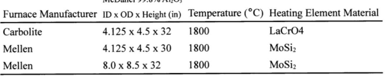
Table 2.1: Vertical tube furnace properties.
Furnace Manufacturer Carbolite Mellen Mellen Tube Dimensions McDanel 99.8% A1203 ID x OD x Height (in) 4.125 x 4.5 x 32 4.125 x 4.5 x 30 8.0 x 8.5 x 32 Maximum Temperature (*C) 1800 1800 1800
Heating Element Material LaCrO4
MoSi2
MoSi2
All the experiments in this study were conducted in one of three resistance-heated, vertical tube furnaces (Table 2.1). The 8.0" ID Mellen furnace was acquired for further scale-up experiments. However, the extremely expensive consumable refractory materials necessary to operate this
furnace made experimentation cost prohibitive. Therefore, the vast majority of experiments detailed in this thesis were conducted in one of the two 4.125" furnaces.
Both heating element materials have limitations with respect to ramp rates. Therefore, all experiments were conducted with ramp rates no greater than 100*C/hr to ensure maximum life of heating elements. As per the design of the temperature controllers, process value (PV) was determined using type B thermocouples located inside the hot zone of the furnace, but outside of the furnace tube. This arrangement was necessary in order to maintain a controlled atmosphere during experimentation. Obviously, this setup meant that the process value on the temperature controller was greater than the actual operating temperature of the electrolysis cell. In order to overcome this challenge, temperature profiles were measured on all furnaces using a 36" type B thermocouple, which was fed into furnace through a Swagelok Ultra-TorrTM fitting on the furnace cap. The smaller Mellen furnace had a temperature differential of ~100*C, while the Carbolite furnace had a temperature differential of ~50*C, due to superior insulation of radiant heat. The temperature differential on the 8" furnace varied considerably, depending on the crucible assembly of the experiment. Therefore, an internal thermocouple was always used with the 8" furnace for real-time measurements of the electrolysis cell.
As mentioned above, the goal of this study was to determine the performance of the anode during scaled-up electrolysis experiments. Therefore, experiments were conducted using one working electrode (anode) and one counter electrode (cathode), with no reference electrode. The greatest factor limiting the length of the experiments was crucible failure. The molten oxide electrolyte has great solubilizing strength of traditional ceramic crucible materials. Therefore, experiments were always conducted using a two crucible design. The electrolyte was contained within a ceramic primary crucible. The primary crucible was then placed within a secondary crucible, which was partially filled with absorbent alumina beads. The furnace tube was then filled partially with additional alumina beads. The goal of this design was to prevent damage the prohibitively expensive furnace tubes or, even worse, the furnace itself. However, as research began on the different electrolyte compositions, it became apparent that crucible redundancy was only effective with certain electrolyte chemistries. Materials engineering challenges with respect
to refractories will be discussed in detail in section 2.1.2.3.1.
2.1.1.1 Design Improvements
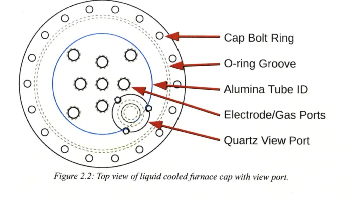
As mentioned above, one of the key challenges associated with MOE is the expedited corrosion reactions caused by the extremely high temperatures and presence of oxygen. Additionally, an important tool for analyzing current efficiency was measuring oxygen concentration of furnace exhaust. Therefore, it is extremely important that the experimental environment remain uncontaminated by the surrounding atmosphere. The cell cap design that was used in previous MOE studies at MIT [8] was determined to be insufficient for the scale-up of the investigation. Therefore, a new cell cap capable of consistently providing a perfect seal was invented.
Previous MOE studies at MIT used a cell cap that sealed to the furnace tube by using a steel collar that fit around the furnace tube, with an O-ring between the outer furnace tube wall and the inner wall of the steel collar [8]. An airtight seal was achieved when the clearance between the outer furnace tube wall and inner steel collar wall was small enough that forcing the collar and O-ring over the furnace tube caused the O-ring to compress and gasket to the tube and collar. However, it was found that if the clearance was too small, it was nearly impossible to get the collar onto the furnace tube without breaking the fragile ceramic tube. Furthermore, if the clearance was too large, the O-ring would not form a gasket. Even if an airtight seal was achieved, the seal would fail if internal pressure of the furnace tube exceeded 1 atm; which was a common occurrence during heating of the furnace. After an extensive search of tube furnace accessories vendors came up empty, the invention of a more robust sealing system was undertaken.
Cap Bolt Ring
Liquid Cooled Cap
Silicon 0-rings
Split Furance Collar Compression Bolt Ring Alumina Furnace Tube
.... ... ... ... .... ... .... ... ... . .... ... ... . ... ... ... ... ... -
-Cap Bolt Ring
lift
*0-ring
Groove
O
O OAlumina
Tube ID
Electrode/Gas Ports
Quartz View Port
O
O
Figure 2.2: Top view of liquid cooled furnace cap with view port.
The author recognized the need for a mechanical compression fitting. This type of fitting would allow the furnace collar to easily slide over the tube, and be subsequently tightened to form a robust gasket. The slip casting method used by the furnace tube vendor (McDanel Advanced Ceramics) results in large radial tolerances of the furnace tubes (OD 4.50" ± 0.180"). Therefore, the mechanical compression fitting had to have a change in internal diameter, upon tightening, that spanned the 0.180" furnace tube tolerance plus the change in O-ring diameter to achieve the nominal vacuum-rated contact pressure of 13 kg/cm2 [21]. The new compression fitting works
by using a bolt ring to join a split collar with a sliding, beveled O-ring groove that compresses a
-425 silicone O-ring (McMaster-Carr Part:9396K363) to the furnace tube (Figure 2.1). The
resulting design has been tested, with a new silicone O-ring, to 20 psi (138 kPa) positive internal pressure differential (equal to 1.4 kN of longitudinal force on the furnace cap), with the furnace
PV at 1600*C, without any detectable leaks.
As mentioned above, an inert atmosphere was crucial for MOE experiments. The MOE cell assembly used in previous studies at MIT achieved an inert atmosphere by purging the furnace with helium for extended periods of time (>12 hours). It is well known that purging with helium can be notoriously difficult, due to its low density. The MOE experiments are particularly difficult to purge due to the porous material used (powder preparation of electrolyte, and use of
alumina beads), and the necessity for the gas inlet to be above the electrolysis bath. Because of this, extremely large amounts of inert gases were used to purge the system. Even then, anomalous spikes in oxygen would be detected during experiments. These oxygen spikes were believed to be caused by degassing of trapped gas during the melting of the electrolyte, or the escape of gas pockets in the alumina beads due to convection upon heating. Previously, the use of a vacuum-purge procedure was avoided due to fear of atmospheric pressure fracturing the fragile furnace tube when under vacuum. However, it was quickly realized that alumina ceramic
is only fragile with respect to tensile stresses, and should be able to easily withstand an evenly distributed compressive force cause by a negative pressure differential inside the furnace tube. Therefore, a vacuum-purge system was designed and installed, instantly making the use of large volumes of inert gas obsolete for purging, as well as eliminating the occurrence of anomalous oxygen spikes.
The final innovation made to the MOE assembly was the design and installation of a view port. As mentioned above, the length of the experiments were determined by the maximum service life of the ceramic crucibles. Despite the redundancy of the crucibles, the molten electrolyte is capable of breaching both crucibles and damaging the expensive furnace tubes and, in some cases, capable of eating through the furnace tubes and damaging the furnace itself. Previously, crucible failure was determined by the loss of electrolytic current. When the electrolyte would breach the primary crucible, the bath level would drop below the height of the anode, causing the electrolysis circuit to open and the current to stop. At this point, the experiment would be immediately stopped. However, due to the slow ramp-down rate (<100*C/hr), it was possible that the electrolyte would continue to breach the secondary containment crucible before the electrolyte would solidify. Therefore, the need for a view port was mandated; not only to protect against crucible failure, but also as a means to observe oxygen evolution during electrolysis (Figure 2.2).
2.1.2 Materials Candidates
technique. However, the practical engineering challenges associated with constructing a working MOE cell call upon the sagacity of the researcher with respect to corrosion engineering and materials compatibility. Not only does the cell require exceptional materials properties as a whole, but the individual components must be considered with regard to their unique corrosive environments. Therefore, the cell must be broken down into it's three major parts (anode, cathode, and crucible/refractories) to determine appropriate materials.
2.1.2.1 Anode
Despite nearly a century of industrial maturation, the aluminum industry has yet to find a suitable inert anode that can withstand the highly corrosive environment and meet the electrochemical and mechanical demands of the Hall-Heroult cell [9;10]. With even higher operating temperatures and faster corrosion kinetics, the search for an inert anode for the MOE cell is a materials engineering challenge in a class of its own. Possible materials classes under investigation are discussed in detail in Chapter 1. This study focused primarily on iridium anodes. However, various materials have also been investigated as possible anode candidates.
2.1.2.1.1 Iridium Anodes
Previous studies at MIT have shown very promising results with iridium as a candidate inert anode material [7;8;22]. Therefore, a main goal of this study was to continue research into the plausibility of an inert iridium anode at a larger scale, and as a function of process parameters.
Anodes were constructed of 99.9% pure iridium obtained from Furuya Metal Co., Japan. The iridium was received in 100mm x 100mm x 1mm sheets. Iridium is very hard and brittle, and has a very high melting temperature, 2446*C [23]. Therefore, fabrication is not possible with traditional machining or casting methods. However, success was enjoyed by fabricating the anodes using a CNC waterjet cutting machine and GTAW welding methods.
The most common anode geometry was 30mm x 10mm x 1mm bars. The anodes were cut from as-received iridium sheets and welded to a 1/8" diameter molybdenum lead wire. The wire was then sheathed in a 1/8" internal diameter, 99.8% alumina tube from McDanel Advanced Ceramics to protect the molybdenum from oxygen evolved during electrolysis. The bottom of the tube was then sealed to the molybdenum/iridium interface with alumina-based refractory paste to prevent any exposure of the molybdenum. This was done not only to prevent corrosion of the molybdenum, but to also prevent the consumption of evolved oxygen by the molybdenum, as the exhaust was analyzed using gas chromatography to calculate anodic current efficiency.
2.1.2.1.1.1 Unique Morphologies
Iridium is a very expensive material to conduct research with due to not only the high cost of the metal itself, but the increased labor costs associated with the difficulty of machining the material. Because of this, experimenting with unique morphologies was difficult using the humble machining capabilities at MIT. However, MIT was afforded a unique opportunity to work with Plasma Processes, a company from Birmingham, Alabama that specializes in state-of-the material and coating fabrication.
Researchers from Plasma Processes collaborated with the author on NASA's lunar oxygen production project as part of an SBIR grant that the company received to research anode fabrication techniques. Plasma Processes manufactured the following anodes using a proprietary molten salt electrodeposition process:
- Iridium-coated graphite - this anode was made from a graphite disc, on which a thin
(~1mm) coating of iridium was deposited. Final geometry: 13mm height x 50mm
diameter disc.
- Porous disc anode - this anode was a porous disc of iridium. Pore size was on the order of 1mm. Final geometry: 13mm height x 50mm diameter disc.
Figure 2.3: Three iridium anodes made by Plasma Processes using a proprietary molten salt electrodeposition process. Left: "Wagon Wheel" anode showcases the ability of the process to deposit solid iridium in unique geometries. Tests with this anode not discussed in this study. Middle: A graphite disc coated with -1mm of iridium.
Right: A porous iridium anode with pore on the order of 1mm. The pores in this photograph are clogged with entrained electrolyte left over from a previous submersion test.
Both of these anodes offered a unique opportunity to test possible engineering solutions to problems associated with the high costs of iridium. Each anode represented different routes that could be investigated to stretch the amperage available per pound of iridium metal used in an MOE cell.
2.1.2.1.2 Other Anode Materials
In addition to the ground-up scientific research aimed at creating the perfect inert anode material, an exhaustive investigation of commercially available refractory electrode materials was necessary. The most obvious application for high temperature electrodes is furnace heating elements. Therefore, vendors of heating elements were primary source to obtain these materials. Among these materials can be found an everyday application of an oxide passivated metal (refer to section 1.2.2.2) called molybdenum disilicide (MoSi2), used for electrical resistance heating.
Molybdenum disilicide is an alloy of two readily oxidized metals. However, it is virtually impervious to corrosion in oxidizing atmospheres up to 1800*C [24]. This excellent corrosion resistance is due to silicon preferentially oxidizing and forming a protective SiO2 layer, which
2.1.2.2 Cathode
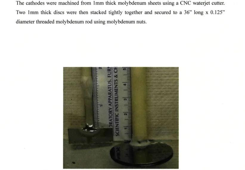
Except for experiments involving novel crucible designs (refer to section 2.1.2.3.2), all experiments were conducted using 50mm diameter x 2mm thick molybdenum disc cathode. In all experiments, the cathode was located below the anode in the cell. Molybdenum was selected, despite its susceptibility to oxidation, because the cathode was covered by slag and always located below the anode in the cell. Therefore, the cathode would never come in contact with the evolving oxygen bubbles or the oxygen-containing atmosphere of the furnace during electrolysis. Furthermore, the cathodic potential should offer protection from oxidation during electrolysis. The cathodes were machined from 1mm thick molybdenum sheets using a CNC waterjet cutter. Two 1mm thick discs were then stacked tightly together and secured to a 36" long x 0.125" diameter threaded molybdenum rod using molybdenum nuts.
Figure 2.4: Iridium anode and molybdenum cathode before electrolysis. . .. .... .. .. ... .. ..... -- -
---2.1.2.3 Crucibles
As mentioned above, the length of experiments was usually determined by the maximum service life of the crucible. Therefore, determining appropriate crucible material became a vital task in order to perform repeatable experiments. In smaller scale MOE studies at MIT, standard high purity alumina crucibles (99.8% A1203 from McDanel Advanced Ceramics) were preferred,
based on a cost-benefit analysis [8]. However, as experimental times became longer, it was soon realized that alumina crucibles were only reliable as slag containers for a maximum of 5 hours above 1550*C. Furthermore, as studies began on different slag chemistries, it was found that crucible performance was greatly affected by the basicity of the slag.
An obvious alternative for ceramic crucibles is the refractory metals (Mo, W, Ta, etc.). These materials were initially avoided due to their susceptibility to oxidize. This was a concern for two reasons. First, it was a concern that the extremely high temperatures would cause runaway oxidation and catastrophic failure. Second, the refractory metals would absorb the electrolytically produced oxygen, leading to false current efficiency measurements. However, it was found that molybdenum crucibles, despite severe oxidation, would last considerably longer than their ceramic counterparts. Furthermore, while the second concern does present an issue when determining current efficiency with respect to oxygen concentration of the furnace exhaust, it is not an issue when current efficiency is determined by concentration of iron in cathodic product; which is a more useful metric for current efficiency measurements for the iron production project.
2.1.2.3.1 Effect of Electrolyte Basicity on Crucible Selection
Working with molten oxides presents unique challenges with regard to refractories, as slags tend to be strong solvents of traditional ceramic refractory materials. Silicates in particular are miscible with most other oxides, and it was understood from the beginning that quartz would be useless as a containment material for any molten oxide system. Furthermore, because of this property, silicate systems will also tend to dissolve through most commonly used ceramic
crucible materials if given enough time.
When studies began with slags of varying composition, it was found that an alumina crucible, which could normally withstand up to 4 hours at MOE operating temperatures with a silicate slag, would be completely dissolved by its contents within an hour when used with a highly basic, calcia-rich slag. Similar to aqueous systems, basic slags will tend to dissolve acidic oxides faster, and vice versa. Therefore, one must take into account optical basicity of the slag when determining the appropriate crucible material. With this taken into account, it was found that silica-free, calcia-rich slags with high optical basicity will be successfully contained in a magnesia (MgO), a basic oxide, for very long times (>10 hours). Conversely, it was found that relatively acidic silicate slags will dissolve magnesia faster than alumina, a slightly acidic oxide.
2.1.2.3.2 Novel Crucible Design
Using the cathode described above has several disadvantages. It is very difficult to perform postmortem analysis on the cathodic product of a molybdenum cathode. The cathode must be lifted out of the electrolyte while still molten to prevent it from becoming permanently encased in the oxide glass that forms upon cooling. If there was a well segregated liquid iron pool on the cathode, the lifting of the cathode causes the molten phases to mix. One is left with an agglomeration of slag, partially oxidized iron-molybdenum alloy, and small porosities on the cathode for analysis. This makes it extremely difficult to determine the morphology of the deposited iron pool and the purity of iron contained therein.
In addition to causing a difficult postmortem analysis, the lead wire necessary for the disc type cathode can fail. MOE experiments can be very complicated, expensive, and extremely vulnerable to failure of any link in the chain. Therefore, it is extremely important that any diagnosis of possible failure mechanisms be remedied whenever possible. Current is fed to the cathode by 1/8" molybdenum rod. Due to the furnace's design, all electrical and gas connections must come in through the furnace cap. Therefore, the current lead to the cathode must run past the anode and through the electrolyte. In order to prevent short-circuiting, as well as protect the
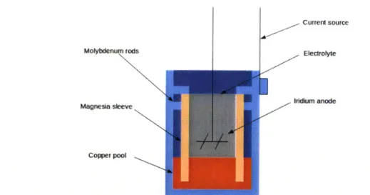
Molybdenum rods Magnesia sleeve Copper pool Current source Electrolyte Iridium anode
Figure 2.5: Novel crucible design to circumvent shortcomings of disc cathodes.
molybdenum rod from oxidation, it is sheathed in a ceramic tube. However, as stated above, the molten electrolyte can eat through the ceramic. And, when this happens, the molybdenum is exposed to oxygen and quickly oxidizes, causing it to lose its electrical conductivity.
In order to circumvent these disadvantages, a novel crucible design which eliminates the need for a molybdenum disc cathode has been tested. The design uses a molybdenum crucible, which is connected to the current supply and supplies cathodic potential to the electrolyte by means of a molten copper pool. Copper was chosen for two main reasons:
- It has low miscibility with both iron and molybdenum - It is more dense than iron, allowing iron to float on top of it
Because of these two key characteristics, the copper pool will allow there to be 3 well segregated strata of copper, iron, and electrolyte. Faradaic reduction reactions take place at the copper/electrolyte interface and a ceramic sleeve keeps the current lines directed vertically down. A cross-sectional model of this crucible design is shown in Figure 2.5.
2.2 Electrolyte Selection
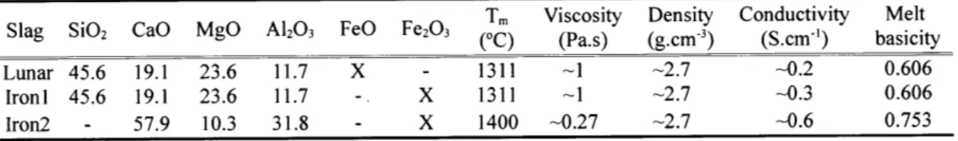
The electrolyte composition for studying MOE as a method to produce oxygen on the moon is fixed by the composition of lunar regolith (refer to section 1.1.2). Conversely, the electrolyte for terrestrial iron production can be selected to best fit the criteria listed in section 1.2.3. Therefore, three electrolytes were used throughout this research (Table 2.2). The first two of these three electrolytes were based on the composition of lunar regolith (minus the highly volatile oxides), whereas the third composition was selected to most closely meet the criteria listed in section
1.2.3.
Table 2.2: Properties of different slags used in this study.
Tm Viscosity Density Conductivity Melt
Slag SiO2 CaO MgO A12O3 FeO Fe203 (0C) (Pa.s) (g.cm3) (S.cm-') basicity
Lunar 45.6 19.1 23.6 11.7 X - 1311 -1 -2.7 -0.2 0.606
IronI 45.6 19.1 23.6 11.7 - X 1311 -1 -2.7 -0.3 0.606
Chapter 3: Experimental Results
3.1 Iridium
3.1.1 Electrodeposited Iridium Anodes
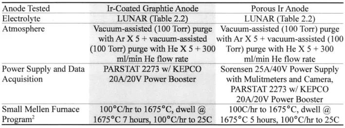
The electrodeposited anodes were tested in the smaller Mellen furnace with a 4.0" ID x 30" L 99.8% furnace tube from McDanel Advanced ceramics. The iridium-coated graphite and porous iridium anodes were tested as feasible means to utilize unique morphologies to circumvent the high capital costs associated with using iridium as an inert anode material. Both anodes were tested with similar process parameters, which are detailed in Table 3.1.
Table 3.1: Parameters of experiments performed with electrodeposited iridium anodes.
Anode Tested Ir-Coated Graphtie Anode Porous Ir Anode
Electrolyte LUNAR (Table 2.2) LUNAR (Table 2.2)
Atmosphere Vacuum-assisted (100 Torr) purge Vacuum-assisted (100 Torr) purge with Ar X 5 + vacuum-assisted with Ar X 5 + vacuum-assisted (100 (100 Torr) purge with He X 5 + 300 Torr) purge with He X 5 + 300
ml/min He flow rate ml/min He flow rate Power Supply and Data PARSTAT 2273 w/ KEPCO Sorensen 25A/40V Power Supply Acquisition 20A/20V Power Booster with Mulitmeters and Camera,
PARSTAT 2273 w/ KEPCO 20A/20V Power Booster Small Mellen Furnace 100*C/hr to 1675*C, dwell @ 1OOC/hr to 1675 *C, dwell @ Program2 1675"C 7 hours, 100*C/hrto 25C 16750C 5 hours, 1000C/hrto 25C
Unfortunately, time constraints and faulty equipment effected the quality of electrochemical data collected for experimentation with the iridium-coated graphite anode. However, the primary goal for testing this anode was whether or not iridium coating would effectively protect the graphite substrate and if the ~-Imm coating would last during electrolysis.
In most MOE tests, the cathode area was substantially larger than the anode area. This was to force the limiting current density to be on the anode rather than the cathode. However, the large 2 Values reported are PVs, please refer to section 2.1.1 for explanation of temperature gradient during experiments.
0.5 12 0.45 0.4 10 E 0.35 Current density 8 0.3 0.25Potential 6 0.2 V 4 0.15 0.1 2 0.05 0 0 0 20 40 60 80 100 120 140 160 180 Time (seconds)
Figure 3.1: Electrolysis data for iridium-coated graphite anode.
size of the electrodeposited anodes and the limited size of the furnace dictated the maximum size of the cathode. Therefore, the cathode for both experiments was a disc measuring 50mm diameter x 0.25mm thick. Details about the anodes used can be found in section 2.1.2.1 .1 .1.
0.5 12 0.4 10 Potential E (0 8 0.3 6 0.2 Current density 4 0.1 2 0 0 0 20 40 60 80 100 Time (minutes)
Figure 3.3: Electrolysis data for porous iridium anode.
As mentioned above, the data acquisition for the iridium-coated graphite anode was flawed due to faulty equipment. The reason is unknown, but after a 4 hour electrolysis experiment only approximately 3 minutes of data was recorded by the potentiostat. However, the author did take notes during the experiment which record that the current response to the potentiostatic
Figure 3.4: Porous iridium anode before (left) and after (right) electrolysis.
![Figure 1.1: Theoretical schematic of an industrial MOE cell [8].](https://thumb-eu.123doks.com/thumbv2/123doknet/14197056.479264/11.918.120.808.142.495/figure-theoretical-schematic-industrial-moe-cell.webp)

![Table 1.33: Selected optical basicities. Adapted from [17].](https://thumb-eu.123doks.com/thumbv2/123doknet/14197056.479264/18.918.204.714.203.519/table-selected-optical-basicities-adapted.webp)