Publisher’s version / Version de l'éditeur:
Vous avez des questions? Nous pouvons vous aider. Pour communiquer directement avec un auteur, consultez la première page de la revue dans laquelle son article a été publié afin de trouver ses coordonnées. Si vous n’arrivez pas à les repérer, communiquez avec nous à PublicationsArchive-ArchivesPublications@nrc-cnrc.gc.ca.
Questions? Contact the NRC Publications Archive team at
PublicationsArchive-ArchivesPublications@nrc-cnrc.gc.ca. If you wish to email the authors directly, please see the first page of the publication for their contact information.
https://publications-cnrc.canada.ca/fra/droits
L’accès à ce site Web et l’utilisation de son contenu sont assujettis aux conditions présentées dans le site LISEZ CES CONDITIONS ATTENTIVEMENT AVANT D’UTILISER CE SITE WEB.
Environmental Science & Technology, 53, 5, pp. 2892-2899, 2019-02-04
READ THESE TERMS AND CONDITIONS CAREFULLY BEFORE USING THIS WEBSITE.
https://nrc-publications.canada.ca/eng/copyright
NRC Publications Archive Record / Notice des Archives des publications du CNRC : https://nrc-publications.canada.ca/eng/view/object/?id=b32fcc03-2c41-4bf8-afa9-ec1022b53b7e https://publications-cnrc.canada.ca/fra/voir/objet/?id=b32fcc03-2c41-4bf8-afa9-ec1022b53b7e
NRC Publications Archive
Archives des publications du CNRC
This publication could be one of several versions: author’s original, accepted manuscript or the publisher’s version. / La version de cette publication peut être l’une des suivantes : la version prépublication de l’auteur, la version acceptée du manuscrit ou la version de l’éditeur.
For the publisher’s version, please access the DOI link below./ Pour consulter la version de l’éditeur, utilisez le lien DOI ci-dessous.
https://doi.org/10.1021/acs.est.8b04244
Access and use of this website and the material on it are subject to the Terms and Conditions set forth at
Characterization and reduction of in-use CH
₄ emissions from a dual
fuel marine engine using wavelength modulation spectroscopy
Sommer, David E.; Yeremi, Miayan; Son, Jeff; Corbin, Joel C.; Gagné,
Stéphanie; Lobo, Prem; Miller, J. Wayne; Kirchen, Patrick
Characterization and Reduction of In-Use CH
4
Emissions from a Dual
Fuel Marine Engine Using Wavelength Modulation Spectroscopy
David E. Sommer,
†Miayan Yeremi,
†Jeff Son,
†Joel C. Corbin,
‡Ste
́phanie Gagné,
‡Prem Lobo,
‡J. Wayne Miller,
§and Patrick Kirchen
*
,††
Department of Mechanical Engineering, University of British Columbia, 2054-6250 Applied Science Lane, Vancouver, British Columbia V6T 1Z4, Canada
‡
Metrology Research Centre, National Research Council Canada, 1200 Montreal Rd, Ottawa, Onatrio K1A 0R6, Canada
§
Department of Chemical and Environmental Engineering, Bourns College of Engineering, University of California, Riverside, California 92521, United States
*
S Supporting InformationABSTRACT: In-use exhaust stream CH4emissions from two
dual fuel marine engines were characterized and strategies for CH4reduction were identified and evaluated. For this, a
low-cost, portable, wavelength modulation spectroscopy (WMS) system was developed. The performance of the developed WMS sensor was assessed using gas standards and demonstrated on a heavy-duty, diesel pilot ignited, direct-injection natural gas research engine through comparison to a flame ionization detector. The WMS sensor was subsequently used to measure the exhaust-stream CH4concentration from
two diesel pilot-ignited, port-injected natural gas engines on a coastal vessel while under normal operation. Using cylinder deactivation to reduce the excess air ratio, λ, and vessel
operation changes to minimize operation at lower loads, the total CH4emission were reduced by up to 33%. The measured,
load specific CH4emissions were subsequently used to identify an improved vessel operation strategy, with an estimated 56−
60% reduction in CH4emissions. These results demonstrate the importance of considering the real-world engine operation
profile for accurate estimates of the global warming potential, as well as the utility of a WMS sensor for characterizing and mitigating in-use CH4emissions.
■
INTRODUCTIONNatural gas, largely composed of methane, is an attractive fuel for reciprocating internal combustion engines due to its significant geographically distributed reserves; lower specific CO2, particulate, and SOxemissions; higher knock resistance;1
and potential for lower NOxemissions. Its generally lower cost
(relative to diesel) makes it particularly attractive for heavy-duty on-road, marine, and off-road applications, where limited fuelling infrastructure and on-board fuel storage limitations are more readily addressed. In addition to the reduced cost of natural gas, the low sulfur content and potential for low NOx
emissions associated with lean, premixed combustion strat-egies, make natural gas a viable solution for marine engines in light of NOx emission and fuel sulfur regulations. This is
particularly relevant for marine vessels operating in emission control areas (ECAs) that must meet International Maritime Organization (IMO) Tier III limits.2 For these applications,
the premixed “dual-fuel” fuelling strategy is commonly used for compression ignition engines,3 where a lean premixed natural gas charge is ignited by a small, direct-injected, diesel “pilot” combustion event.
Despite the benefits of natural gas, emission of unburned methane in the exhaust stream remains a challenge, and the strong infrared absorption of CH4 makes it a significant
greenhouse gas (GHG) even at low concentrations, resulting in a higher Global Warming Potential (GWPCH4,100 = 28)4
relative to CO2. Compression ignition engines are often
preferred over spark ignited engines due to their higher compression ratios and associated efficiency, although the commonly used dual fuel strategies can result in high CH4
emissions that cannot be treated using typical aftertreatment catalysts, particularly at low engine loads. For example, two prior studies of retrofit dual fuel conversions for diesel engines in heavy-duty on-road applications reported a net increase in the GWP by a factor of 1.6−4.8 (considering a 100 year horizon) over the Supplemental Emission Test,5 and an increase of 50−127% of equivalent CO2emissions (GWPCH4=
Received: July 31, 2018
Revised: January 31, 2019
Accepted: February 4, 2019
Published: February 4, 2019
pubs.acs.org/est
Cite This:Environ. Sci. Technol. 2019, 53, 2892−2899
34) over the European Transient Cycle,6 relative to diesel operation. The latter study also considered the use of an exhaust oxidation catalyst, but no significant CH4 reductions
were observed. There are relatively few investigations of the CH4emission from dual fuel engines for marine applications;
however, significant reductions in the particulate, NOx, and CO2 emissions were observed for a liquefied natural gas
(LNG) dual fuel ferry, relative to operation with marine gas oil.7 In addition, the total hydrocarbons and CO emissions increased at lower loads. The hydrocarbon emissions were found to increase by a factor of 3−5 as load was decreased from 90% to 29%, a significant fraction of which was expected to be CH4(∼85%).
Several strategies for CH4 mitigation have been proposed,
including cylinder deactivation, pilot injection modification, and exhaust gas aftertreatement. The latter is very effectively applied for pollutants such as CO, NOx, particulate matter, and nonmethane hydrocarbons (NMHC), but a cost-effective suitable system is not yet available for CH4,8 particularly at
lower engine loads and low exhaust temperatures. Cylinder deactivation, discontinues fuelling to individual cylinders at low loads, while the remaining cylinders are operated at a higher specific load, which results in higher low-load exhaust temperature and efficiency.9 In a numerical study, the application of cylinder deactivation was evaluated for a medium-speed marine engine and found to result in NOx reductions and improvement in combustion efficiency, which was expected to decrease CH4emissions, though this was not
explicitly modeled.10 As another approach, the pilot injection can be modified to reduce the CH4emissions. For heavy-duty,
on-road engines, the application of a split diesel pilot injection with advanced timing was found to result in a CH4reduction
with no NOxpenalty.11Similar benefits have been noted for
medium-speed engines12typical of marine applications, where reductions in the inlet pressure were also used to decrease CH4
emissions.
To mitigate the CH4 emissions, the in-use CH4 emission
rates must be considered under realistic engine operating conditions. Exhaust stream CH4and nonmethane hydrocarbon
(NMHC) emissions are commonly measured using a flame ionization detector (FID), although this only measures the total hydrocarbon concentration. An oxidation catalyst (“cutter”) can be used upstream of the FID to oxidize any NMHC, so that only CH4is detected; however, the efficiency
of the catalyst must be considered.13 FID systems rely on a flame for ionization of the sample and require instrument grade fuel and oxidizer, presenting challenges for mobile applications. As an alternative, broad spectrum light absorption techniques, such as Fourier transform infrared (FTIR) spectroscopy, do not require catalytic pretreatment for CH4measurements, nor
do they typically require process gases, making them better suited to in-use (mobile) CH4measurement (e.g., ref6). The
FTIR can be costly, require method development for multispecies exhaust stream mixtures, and may prove to be too bulky, particularly for on-road applications.13 Solid state sensors are commonly used for O2characterization in engine
exhaust, but CH4 detection is susceptible to significant cross
sensitivity to other hydrocarbons.14
Laser absorption techniques centered around a single wavelength are well suited for concentration quantification of a known gas species, as they can be highly selective and relatively inexpensive. Examples of such techniques include: direct laser absorption, scanned wavelength spectroscopy,15
cavity enhanced techniques,16 and photoacoustic spectrosco-py17all having their respective strengths and weaknesses. Direct laser absorption techniques provide simple interpreta-tion of the resulting transmitted signal,15but are susceptible to drift and1f noise.18Scanning the laser wavelength across an
absorption peak increases the amount of spectral information19 and provides a recurring off-peak reference signal, making these techniques more resistant to laser drift, window contamination, or scattering by particulate matter in the sample.15 In so-called wavelength modulation spectroscopy
(WMS), a smaller amplitude high frequency modulation of the wavelength is combined with a relatively slow wavelength scan across an absorption peak. The high frequency modulation reduces 1f noise and, coupled with homodyne detection,
provides a further increase in signal-to-noise ratio. WMS has been previously demonstrated for NH3 measurements in the
exhaust stream of diesel engines equipped with selective catalytic reduction aftertreatment systems,20but not for CH
4.
WMS is selected for this work because of its resilience to window contamination, methane selectivity, suitability to concentrations typical of dual-fuel engine exhaust, and potential for high-speed in situ exhaust measurements.
In the current work, a portable CH4sensor is developed on
the basis of WMS for characterization of CH4emissions from
in-use natural gas enginesthe cost of constructing the sensor was approximately an order of magnitude less than purchasing a commercial CH4measurement system (e.g., FTIR or FID).
The WMS sensor performance is characterized against a reference instrument using gas standards and exhaust samples from a research engine. The WMS system is subsequently applied to measure the CH4 emissions from two dual fuel
engines on a coastal marine vessel under typical operating conditions, as well as to evaluate potential engine control and vessel operating strategies for CH4reduction. This work is part
of an ongoing project aimed at reducing CH4emissions from
natural gas engines.
■
METHODSThe CH4 measurement system was developed to provide a
low-cost approach for measurements of exhaust stream CH4
emissions from in-use mobile and field (i.e., nonlaboratory) engine applications. The sensor development and calibration, as well as the considered engines are described below.
Wavelength Modulation Spectroscopy. Wavelength modulation spectroscopy (WMS) is a light absorption technique for detection of gaseous species using tunable laser diodes. A short overview of WMS in the context of the system developed here is provided in the Supporting Information (SI); however, interested readers are referred to a recent review article for a more complete discussion.15 The WMS system developed here, shown inFigure 1, passes light from a fiber-coupled 1651 nm distributed feedback laser (Norcada NL1651-B) through a 180 cm3, 36 cm long, measurement cell
containing the sample gas. This wavelength was selected for the relatively strong CH4 absorption characteristics, lack of
cross-sensitivity to other exhaust species, low cost, and suitability for use with conventional photodetectors.
To reduce the system cost, a commercial data acquisition system (National Instruments USB 6361) and software (LabVIEW) were used for the signal generation, data acquisition, and signal processing, negating the need for hardware-based signal generators or a lock-in amplifier.21The
Environmental Science & Technology Article
DOI:10.1021/acs.est.8b04244
Environ. Sci. Technol. 2019, 53, 2892−2899
system cost can be further reduced through the use of purpose-built signal generators and data acquisition systems. With the selected scanning and modulation frequencies (10 Hz and 20 kHz, respectively), the system has a temporal resolution of 20 Hz, as the absorption peak is crossed twice per scanning period (seeSI), although the response time is limited by gas transport delays. Similar to other WMS systems, the concentration was correlated to the magnitude of the light absorption signal at the second harmonic (2H) of the modulation frequency.21The 2H signal was chosen due to its improved noise rejection relative to the first harmonic, improved signal strength relative to higher harmonics, and insensitivity to sample chamber pressure variations observed in this study. Details of the sensor hardware, signal generation, and postprocessing can be found in theSI.
Gas samples are drawn from the engine exhaust and treated before entering the WMS measurement chamber. The sampling system included exhaust gas extraction, water removal, and mechanical filtering, as well as a universal exhaust gas oxygen sensor (UEGO, Bosch LSU 4.9) to estimate the excess air ratio,
λ= m m m m / ( / ) a f a f stoich (1)
where ma and mf are the inducted air and fuel masses,
respectively, and “stoich” refers to the stoichiometric air-fuel ratio. The excess air ratio is considered as it provides insight into the engine operating strategy and is known to have a significant impact on the hydrocarbon (and CH4) emissions.22
Furthermore, the excess air ratio is used to estimate the water vapor content in the exhaust stream. Details of the sampling system and vapor content estimation are provided in theSI.
Calibration. The WMS system was calibrated by correlating the peak magnitude of the 2H time domain signal against secondary CH4 concentration standards (500 ppm,
1000 ppm, 3900 ppm, 1%, 4% CH4, all balance N2). For the
1% and 4% CH4 standards, the optical densities were α ≈
0.025 and α ≈ 0.12, respectively, and can no longer be treated as optically thin (α ≲ 0.05) and the 2H response to CH4
concentration is then not linear.23As a result, the 2H response of the WMS was parametrized using a second order polynomial for the range of 500 ppm to 4%, based on least-squares optimization. No systematic drift in the calibration signals was observed before, during, or after field measurement (∼100 h of laser time).
Considered Engines.This study considered two engines with different natural gas fuelling strategies. The performance of the WMS for exhaust stream CH4 concentration
measure-ment was assessed on a research engine through comparison to a flame ionization detector. In addition, the WMS was used to
quantify the in-use CH4 emissions of a natural gas fuelled
marine vessel and to evaluate CH4 mitigation strategies. A
summary of the main specifications for each of the considered engines is given in Table 1. The relevant operational considerations of each engine are discussed with the results.
■
RESULTS AND DISCUSSIONResearch Engine.The exhaust stream CH4concentration
from a single cylinder research engine was measured using the WMS system, as well as a flame ionization detector (FID, AVL CEBII). Details of the research engine facility and fuel system can be found in refs24and25. The diesel pilot ignited direct injection natural gas strategy applied on this engine allowed a wide range of exhaust stream CH4 concentrations to be
considered through modifications to the injection strategy. A typical injection schedule consists of a small diesel injection (∼5% total energy content) near piston top dead center (TDC), followed by direct injection of natural gas. This results in a nonpremixed combustion mode with low CH4emissions,
relative to premixed natural gas combustion strategies.26The nominal engine operating conditions are given inTable 2. To
provide a wide range of exhaust stream CH4concentrations, a
second, late injection of natural gas was used to intentionally increase exhaust stream CH4 concentration. The relative
timing θinj,2 and pulse width τinj,2 of the second natural gas
injection were varied to affect the CH4emissions. It should be
noted that such an operating strategy and the resulting CH4
concentrations are not representative of an actual operating strategy for a direct injection natural gas engine, but are used here to assess the WMS system.
The exhaust stream CH4 concentrations measured by the
WMS system are compared to those measured by the FID in Figure 2. Error bars indicate 95% of the measured data over the measurement duration. The FID sensor has a specified repeatability of ±20 ppm which is also included in the error bars of Figure 2. For the range of CH4 concentrations
considered, a strong agreement was seen between the two instruments. As the FID is sensitive to all hydrocarbons, the efficiency of the catalytic cutter (used to isolate CH4 from
Figure 1.Schematic overview of the WMS system architecture.
Table 1. Specifications of Considered Natural Gas Engines
research engine marine engine
#of cylinders 1 9
cycle 4 stroke 4 stroke
NG fuelling late cycle direct injection port injection ignition diesel pilot compression ignition
displacement [L/cyl] 2.5 36
mean piston speed [m/s] 3.4−11.8 10
Table 2. Considered Operating Conditions for the Single Cylinder Research Enginea
IMEP ∼7.5 bar
mean piston speed 6.8 m/s
λ ∼3.2 τ inj,main 1.1 ms τinj,2 0.38···0.68 ms θ inj,2 50°··· 87° aTDC
aIMEP: indicated mean effective pressure; aTDC: after top dead
other hydrocarbons) was taken into consideration, as any non-CH4exiting the catalyst will be detected as CH4 by an FID.
The strong agreement between the two systems indicates that the WMS system is suitable for exhaust stream measurements. In-Use CH4Emissions of Dual-Fuel Ship Engines.After
validation of the WMS on the research engine, it was used to measure the in-use CH4emissions from two dual fuel natural
gas engines on a marine vessel during typical daily operations in coastal waters. For dual fuel engines, natural gas is injected into the intake port upstream of the intake valve, where it mixes with air and is drawn into the cylinder. The premixed charge is compressed and subsequently ignited with a small (∼2% total energy content) diesel pilot injection near TDC. The engines considered here operate at constant speed to drive electrical generators at varying load. The methane content of the natural gas was 91−95%.
Measurements were carried out at steady-state engine loads by operating one engine at a constant load, while the load of the other engine was allowed to vary to meet the vessel propulsion demands. This method was used to achieve stable load points for 5 min for loads >30%. At lower loads (≤30%) the vessel’s bow thrusters were used while in berth to establish a steady engine load for at least 3 min. The exhaust temperature and λ were monitored to ensure stable engine operation prior to measurement. Exhaust gas CH4
concen-tration measurements from the WMS system are used in conjunction with an exhaust gas mass flow rate model, which is described in theSI, to obtain an estimate of the brake specific CH4emissions across the load range.
The CH4emissions at the steady-state load points are shown
in Figure 3 for Engines 1 and 2 for the considered loads, ranging from hotel power (∼5% load) to cruising speed on a single engine (∼92% load). The error bars (Figure 3) indicate the 95% confidence interval of the measured data over the duration of the steady load operating point, which was the most significant uncertainty. Sensor drift was assessed with span gases of 3900 PPM, 1%, and 4% CH4, at the beginning
and end of each measurement block (multiple times daily). The relative change did not exceed 5% for any span gas calibration, and no systematic drift was observed over the several days of on-ship measurement. Three bagged samples of exhaust gas were characterized by an independent lab for gas chromatograph (GC) analysis for 5% load on engine 1, and 25% load for both engine 1 and engine 2. The concentrations from the GC were within 10% of those measured with the
WMS system, which is similar to the discrepancy that was observed for a span gas control sample.
Each engine utilized a different operating strategy. Engine 1 implemented the standard (as delivered) engine control strategy, while Engine 2 utilized a cylinder deactivation strategy for loads below 15% to reduce CH4emissions. The
cylinder deactivation strategy is discussed in detail in a subsequent section. For both operating strategies, the CH4
emissions increased significantly with decreasing load; however, the application of the cylinder deactivation strategy resulted in a significant reduction at lower loads. The mechanisms for the high CH4 at lower loads, as well as a
discussion of the cylinder deactivation strategy are presented in subsequent section. At loads where there was no difference in the operating strategy (i.e., > 15%), there were no significant differences in the CH4 emissions between the engines. The
increased CH4emissions with decreasing load is in agreement
with a previous study;7 however, the lower loads considered (i.e., < 29%) here show the significant increase in CH4
emission at very low loads, which may be relevant depending on the operating characteristics of the vessel. A comparison of the measured CH4emissions with those previously reported in
the literature is provided in theSI(Figure S4).
To elucidate the contributions of CO2 and CH4 to the
GWP, the brake specific GWP (equivalent CO2 emissions,
GWPCH4,100 = 284) is shown in Figure 4, for operation with
Figure 2.Comparison of WMS sensor and FID (AVL CEB-II) for the research engine CH4exhaust measurements.
Figure 3.Specific CH4emissions as a function of steady state engine
load for the two dual fuel marine engines. Engine 1 used the original unmodified strategy (all cylinders firing at all loads), while Engine 2 used a modified strategy to deactivate 3 cylinders at loads below 15%.
Figure 4.Estimated combined global warming potential of CO2and
CH4 at different engine operating conditions. CH4 emissions
converted to CO2 equivalent assuming a 100 year horizon
(GWPCH4,100= 28).4
Environmental Science & Technology Article
DOI:10.1021/acs.est.8b04244
Environ. Sci. Technol. 2019, 53, 2892−2899
both the conventional engine control strategy, as well as with deactivation of three cylinders below 15% load. The CO2
emissions are estimated based on the measured CH4 and λ.
This estimation had an average error of <4%, relative to measured CO2 emissions. At high loads, the GWP is largely
defined by the CO2emissions, while at lower loads the CH4
emissions play a much stronger role and result in a significant increase in total GWP. The high specific GWP indicates the importance of these low load conditions and the need for CH4
reduction at low loads, as well as the importance of the vessel operation to minimize operation in this load regime. InFigure 4there is an increase in the specific CO2emissions at lower
loads due to decreased mechanical efficiency,27which has also been noted for diesel engines.7The specific CO2emissions for
this dual fuel engine are 8−28% lower than those from HFO and MGO fuelled engines,28 although a comprehensive comparison is beyond the scope of this investigation.
Analysis and Mitigation of High CH4 Emissions at
Low Engine Loads.Because of this significant climate impact of the low load operation, the mechanism for low load CH4
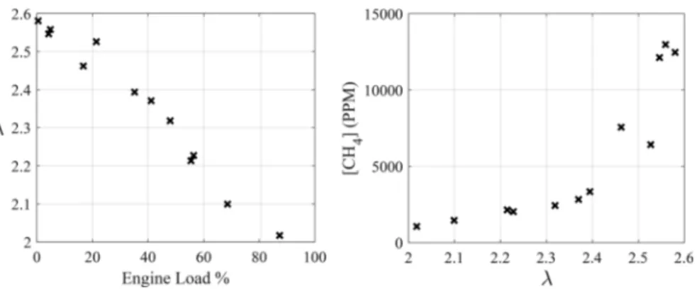
emissions and their mitigation using cylinder deactivation was considered. As shown in Figure 5, operation at low loads results in leaner air-fuel mixtures (i.e., λ increases). The increase in λ with decreasing load is typical for compression ignition engines without additional throttling,10where the air mass cannot be reduced proportional to fuel mass reduction. The increase in CH4 emissions observed at loads ≲40%, is
attributed to decreased flame speeds for the leaner mixtures.29 Also shown inFigure 5(right) are the CH4emissions for the
corresponding λ at all considered loads. For λ ≳ 2.4, CH4
increases more significantly, which may indicate that the mixture is approaching the lean flammability limit where flame propagation cannot be sustained. The actual value of λ at which this transition occurs is expected to be a function of engine design (e.g., compression ratio, combustion chamber design), engine operation (e.g., inlet temperature, pressure, injection settings), and fuel properties.30,31
Because of the observed increase in CH4emissions at low
loads and associated high λ, a cylinder deactivation strategy was implemented by the engine manufacturer at loads below 15%. To reduce CH4 emissions, cylinder deactivation stops
natural gas injection to a number of cylinders, and to maintain the same total brake power, the quantity of natural gas injected into the remaining fired cylinders increases. The increased natural gas supplied to the remaining fired cylinders decreases the excess air ratio of the fired cylinders, termed here the effective excess air ratio, λeff,
i k jjjjj j y { zzzzz z λ =λ + − − n n n n 1 eff skip total2 skip total
1
(2) where nskipis the number of deactivated cylinders, and ntotalis
the total number of cylinders.Equation 2assumes that changes in the volumetric and brake efficiencies due to cylinder deactivation are negligible.
The effect of cylinder deactivation on λeff and CH4
concentration are shown in Figure 6 for very low loads
(4.5%−5.4%) where the CH4emissions are highest. As more
cylinders are deactivated, λeff decreases, resulting in a 65%
reduction in exhaust gas CH4 concentration when six of the
nine cylinders are active. A cylinder deactivation strategy with three deactivated cylinders (i.e., six firing cylinders) at loads below 15% was implemented on Engine 2, as shown inFigure 3. With this strategy, a marked reduction in exhaust gas CH4
emissions (∼50% reduction) is noted for loads below 15%. This strategy also results in a reduction in the GWP (Figure 4) at lower loads. A small increase in CO2emission is observed
for cylinder deactivation operation as a result of the improved combustion efficiency in the firing cylinders. The GWP of this increased CO2is far outweighed by the associated reduction in
CH4and its much more significant GWP100.
Vessel Operational Changes to Mitigate CH4
Emis-sions. Given that the CH4 emissions of the ship vary
significantly with engine load, it is important to consider how vessel operation affects engine load, and in turn, CH4
emissions. To this end, the engine loads were recorded at 30 s intervals for two periods of typical vessel operation, each Figure 5.Effect of engine operating condition on exhaust methane concentration for Engine 1. Excess air ratio (λ) at considered engine loads (left), and CH4exhaust concentration as a function of λ (right).
Figure 6. Effect of cylinder deactivation on exhaust gas CH4
concentration and effective excess air ratio λeffat low loads (4.5%−
period being approximately one month long. Using these data, the influence of engine loading strategies on the total CH4
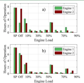
emissions were quantified. Figure 7 shows the daily average
load profiles for both engines during the two considered periods. In Period 1 (Figure 7a)), the vessel was operated in a normal fashion: two engines were typically used to provide the propulsion load with the load shared equally. When at berth for short periods of time, one engine would provide hotel power (∼5% load) to the ship. For longer stops (>3 h), the ship’s electrical system was connected to shore power and both engines were turned off. In Period 2 (Figure 7b)), a single engine was used to provide propulsion power, when possible, to increase the engine load and decrease λ and CH4emissions
(seeFigure 4). Also in Period 2, the vessel operator used shore power (SP) more frequently to avoid operation at low engine loads while in berth. Because of the vessels’ repeated, relatively short route, weather variations between the two periods do not significantly affect operation. The average temperature during period 1 and 2 was 3.4 °C, and 14.8 °C respectively; which is not expected to affect the CH4emissions. The daily maximum
speed and direction did not vary by more than 1.5 m/s and 1° between the two periods, respectively.
To estimate the impact of these strategies on the CH4
emissions, the average daily CH4 emissions were estimated
based on the steady-state measurements and the engine load history. A daily average value is considered as the vessel’s application results in relatively similar operation profile on a daily basis. Under the assumption that the engine is operating in a quasi-equilibrium fashion and that the CH4emissions are
only affected by load, the average daily CH4 emission is
estimated using the following:
∫
λ ̅ = ̇ τ 3 m M n X t m M t ( ( )) ( ) d CH CH d 0 CH exh mix 4 4 4 (3) where M is the molar mass, ndis the number of days in a givenperiod, τ is the duration of the period, 3 t() is the instantaneous engine load, XCH4 is the exhaust CH4 mole
fraction, and ṁexhis the exhaust gas mass flow rate. The mass
flow rate of exhaust gases is estimated by modeling the engine
as a positive displacement pump with a volumetric efficiency parametrized based on the engine manufacturers specification. Details of this model are provided in theSI.
The reductions in the daily average CH4emissions from the
vessel for Periods 1 and 2, with and without cylinder deactivation are given in Table 3. All values are given as a
percent reduction relative to Period 1 without cylinder deactivation. The operating strategy employed in Period 2, with increased specific engine load (using only one engine more frequently) and reduced low engine load (by using shore power more frequently), shows a 12% decrease in estimated average daily CH4 methane emissions. A 23% and 33%
reduction in estimated methane emissions is observed by the use of the cylinder deactivation strategy for Periods 1 and 2, respectively.
To identify a target for CH4 emission reduction through
changes in vessel operation, a scenario was modeled based on the vessel power requirements during Period 2. For this scenario (Table 3, “Min. CH4 Scenario”), a single engine is
used whenever possible (i.e., required power ≤ rated power for a single engine), and shore power is used whenever the vessel is in berth for more than 30 min. In this scenario, the engines are assumed to be started and stopped instantaneously as required to meet the vessel power demands; however, in practice, engine life, safety, and operator preference need to be considered. CH4 emissions reductions of 56% and 60% are
estimated for the considered vessel and duty cycle, with and without cylinder deactivation, respectively. The reduction due to cylinder deactivation is not as significant for this scenario as the low load regime, where cylinder deactivation is active, is avoided. This indicates the importance of GWP reductions possible through operational modifications, as well as technological or engine control modifications. The vessel operator is implementing changes to their operation and terminal facilities to move toward this optimal operating scenario.
The strong dependence of the GWP on the operational profile for dual fuel engines, particularly at low load, demonstrates the necessity for in-use CH4 emissions to be
characterized for individual applications. The WMS system developed here provides a low-cost solution for in-use CH4
measurements for mobile applications. Such data can be used to drive policy decisions, as well as to identify and evaluate engine control and operating strategies for real-world CH4and
thus greenhouse gas reductions. The strategies for CH4
emission reduction (e.g., avoiding low-load operation, cylinder deactivation) described herein are expected to be transferable to other port injected dual-fuel engines, although the realized CH4emissions would vary across different engine types, sizes,
fuel composition, and operation. Figure 7.Average daily ship engine usage during: a) Period 1, and b)
Period 2. For b), more effort was made to use one engine when possible to increase the load, and idling was avoided by using shore power more frequently.
Table 3. Estimated Reductions in Average Daily CH4
Emissions m̅CH4during Periods with Different Operating
Strategies, with and without Deactivation of Three Cylinders at or below 15% (Cyl. Deact.)
cyl. deact.
operation off on
period 1 23.1%
period 2 12.4% 32.9%
min. CH4scenario 56.4% 60.0%
Environmental Science & Technology Article
DOI:10.1021/acs.est.8b04244
Environ. Sci. Technol. 2019, 53, 2892−2899
■
ASSOCIATED CONTENT*
S Supporting InformationThe Supporting Information is available free of charge on the ACS Publications websiteat DOI:10.1021/acs.est.8b04244.
Details of the wavelength modulation spectroscopy system; a description of the exhaust gas sampling system; details of the method used to estimate exhaust flows and composition; and a comparison of emissions from other dual-fuel ship engines (PDF)
■
AUTHOR INFORMATION Corresponding Author *E-mail:pkirchen@mech.ubc.ca. ORCID Joel C. Corbin:0000-0002-2584-9137 Prem Lobo:0000-0003-0626-6646 Patrick Kirchen: 0000-0002-1154-8923 NotesThe authors declare no competing financial interest.
■
ACKNOWLEDGMENTSWe are grateful for the technical support from Dr. Steven Rogak, Oliver Terry, Mike Karpinski-Leydier, and Rene Zepeda during the development and validation of the WMS system. We would also like to acknowledge Brett Smith (National Research Council Canada), as well as Weihan Peng, Jiacheng Yang (University of California Riverside), and Una Trivanovic (University of British Columbia) for the productive collaboration and measurement campaign. The cooperation of the ship operator and their initiative and concern to reduce their environmental impact is greatly appreciated. Funding from the NSERC PGS, Discovery Grant, and CREATE (Clean Combustion Engines) programs, as well as Transport Canada and the United States Maritime Administration is also most gratefully acknowledged. Any conclusions or recommendations expressed in this work are those of the authors and do not necessarily reflect the views of the ship operator or the sponsoring agencies.
■
REFERENCES(1) Wei, L.; Geng, P. A Review on Natural Gas/Diesel Dual Fuel Combustion, Emissions and Performance. Fuel Process. Technol. 2016, 142, 264−278.
(2) United States Environmental Protection Agency. Designation of North American Emission Control Area to Reduce Emissions from Ships; 2010.
(3) Karim, G. A. Dual-Fuel Diesel Engines; CRC Press, 2015. (4) Myhre, G.; Shindell, D.; Bréon, F.-M.; Collins, W.; Fuglestvedt, J.; Huang, J.; Koch, D.; Lamarque, J.-F.; Lee, D.; Mendoza, B.; Nakajima, T.; Robock, A.; Stephens, G.; Takemura, T.; Zhang, H. In Climate Change 2013: The Physical Science Basis. Contribution of Working Group I to the Fifth Assessment Report of the Intergovernmental Panel on Climate Change; Stocker, T., Qin, D., Plattner, G.-K., Tignor, M., Allen, S., Boschung, J., Nauels, A., Xia, Y., Bex, V., Midgley, P., Eds.; Cambridge University Press: Cambridge, United Kingdom and New York, 2013; Chapter 8.
(5) Besch, M. C.; Israel, J.; Thiruvengadam, A.; Kappanna, H.; Carder, D. Emissions Characterization from Different Technology Heavy-Duty Engines Retrofitted for CNG/Diesel Dual-Fuel Oper-ation. SAE Int. J. Engines 2015, 8, 2015−01−1085 DOI: 10.4271/ 2015-01-1085.
(6) Stettler, M. E.; Midgley, W. J.; Swanson, J. J.; Cebon, D.; Boies, A. M. Greenhouse Gas and Noxious Emissions from Dual Fuel Diesel
and Natural Gas Heavy Goods Vehicles. Environ. Sci. Technol. 2016, 50, 2018−2026.
(7) Anderson, M.; Salo, K.; Fridell, E. Particle- and Gaseous Emissions from an LNG Powered Ship. Environ. Sci. Technol. 2015, 49, 12568−12575.
(8) Meng, F.; Wijesinghe, A.; Colvin, J.; LaFleur, C.; Haut, R. Conversion of Exhaust Gases from Dual-Fuel (Natural Gas-Diesel) Engine under Ni-Co-Cu/ZSM-5 Catalysts. SAE 2017−01−0908 SAE Tech. Pap. Ser. 2017, DOI: 10.4271/2017-01-0908.
(9) Ramesh, A. K.; Shaver, G. M.; Allen, C. M.; Nayyar, S.; Gosala, D. B.; Caicedo Parra, D.; Koeberlein, E.; McCarthy, J.; Nielsen, D. Utilizing Low Airflow Strategies, including Cylinder Deactivation, to Improve Fuel Efficiency and Aftertreatment Thermal Management. Int. J. Engine Res. 2017, 18, 1005−1016.
(10) Konrad, J.; Lauer, T.; Moser, M.; Zhu, J. Investigation of the Cylinder Cut-out for Medium-speed Dual-fuel Engines. MTZ. Industrial 2018, 8, 56−63.
(11) Yousefi, A.; Guo, H.; Birouk, M. An Experimental and Numerical Study on Diesel Injection Split of a Natural Gas/Diesel Dual-Fuel Engine at a Low Engine Load. Fuel 2018, 212, 332−346. (12) Henke, B.; Andree, S.; Buchholz, B.; Theile, M. Pilot Injection Strategies for Medium-speed Dual-fuel Engines. MTZ. Industrial 2018, 8, 48−55.
(13) Wright, N.; Osborne, D.; Music, N. Comparison of Hydro-carbon Measurement with FTIR and FID in a Dual Fuel Locomotive Engine. SAE 2016−01−0978 SAE Tech. Pap. Ser.2016, DOI:
DOI: 10.4271/2016-01-0978.
(14) Dutta, A.; Nishiguchi, H.; Takita, Y.; Ishihara, T. Amperometric hydrocarbon sensor using La(Sr)Ga(Fe)O3 solid electrolyte for monitoring in exhaust gas. Sens. Actuators, B 2005, 108, 368−373.
(15) Goldenstein, C. S.; Spearrin, R. M.; Jeffries, J. B.; Hanson, R. K. Infrared Laser-Absorption Sensing for Combustion Gases. Prog. Energy Combust. Sci. 2017, 60, 132−176.
(16) Harris, S. J. Intracavity laser spectroscopy: an old field with new prospects for combustion diagnostics. Appl. Opt. 1984, 23, 1311− 1318.
(17) Webber, M. E.; Pushkarsky, M.; Patel, C. K. N. Fiber-amplifier-enhanced photoacoustic spectroscopy with near-infrared tunable diode lasers. Appl. Opt. 2003, 42, 2119−2126.
(18) Petermann, K. Laser Diode Modulation and Noise; Springer, 2012; Vol. 3.
(19) Witzel, O.; Klein, A.; Wagner, S.; Meffert, C.; Schulz, C.; Ebert, V. High-Speed Tunable Diode Laser Absorption Spectroscopy for Sampling-Free in-Cylinder Water Vapor Concentration Measure-ments in an Optical IC Engine. Appl. Phys. B: Lasers Opt. 2012, 109, 521−532.
(20) Du, Z.; Yan, Y.; Li, J.; Zhang, S.; Yang, X.; Xiao, Y. In situ, multiparameter optical sensor for monitoring the selective catalytic reduction process of diesel engines. Sens. Actuators, B 2018, 267, 255−264.
(21) Zheng, C. T.; Huang, J. Q.; Ye, W. L.; Lv, M.; Dang, J. M.; Cao, T. S.; Chen, C.; Wang, Y. D. Demonstration of a Portable Near-Infrared CH4 Detection Sensor based on Tunable Diode Laser Absorption Spectroscopy. Infrared Phys. Technol. 2013, 61, 306−312. (22) Papagiannakis, R. G.; Rakopoulos, C. D.; Hountalas, D. T.; Rakopoulos, D. C. Emission Characteristics of High Speed, Dual Fuel, Compression Ignition Engine Operating in a Wide Range of Natural Gas/Diesel Fuel Proportions. Fuel 2010, 89, 1397−1406.
(23) Rieker, G. B.; Jeffries, J. B.; Hanson, R. K. Calibration-Free Wavelength-Modulation Spectroscopy for Measurements of Gas Temperature and Concentration in Harsh Environments. Appl. Opt. 2009, 48, 5546−5560.
(24) Faghani, E. Effect of Injection Strategies on Particulate Matter Emissions From HPDI Natural Gas Engines. PhD, University of British Columbia, 2015.
(25) McTaggart-Cowan, G. P. Pollutant Formation in a Gaseous-Fuelled, Direct Injection Engine. PhD, University of British Columbia, 2006.
(26) Ouellette, P.; Goudie, D.; McTaggart-Cowan, G. Progress in the Development of Natural Gas High Pressure Direct Injection for Euro VI Heavy-Duty Trucks. Internationaler Motorenkongress 2016, 591−607.
(27) Heywood, J. Internal Combustion Engine Fundamentals, 1sted.;
McGraw-Hill, 1988.
(28) Brynolf, S. Environmental assessment of present and future marine fuels. PhD, Chalmers University of Technology, 2014.
(29) Karim, G.; Liu, Z.; Jones, W. Exhaust Emissions from Dual Fuel Engines at Light Load. SAE 932822 SAE Tech. Pap. Ser.1993,
DOI: 10.4271/932822.
(30) Rochussen, J.; Yeo, J.; Kirchen, P. Effect of Fuelling Control Parameters on Combustion and Emissions Characteristics of Diesel-Ignited Natural Gas Dual-Fuel Combustion. SAE 2016−01−0792 SAE Tech. Pap. Ser. 2016, DOI: 10.4271/2016-01-0792.
(31) Turns, S. An Introduction to Combustion: Concepts and Applications; McGraw-Hill, 2012.
Environmental Science & Technology Article
DOI:10.1021/acs.est.8b04244
Environ. Sci. Technol. 2019, 53, 2892−2899