HAL Id: hal-02465815
https://hal.archives-ouvertes.fr/hal-02465815
Submitted on 4 Feb 2020
HAL is a multi-disciplinary open access
archive for the deposit and dissemination of sci-entific research documents, whether they are pub-lished or not. The documents may come from teaching and research institutions in France or abroad, or from public or private research centers.
L’archive ouverte pluridisciplinaire HAL, est destinée au dépôt et à la diffusion de documents scientifiques de niveau recherche, publiés ou non, émanant des établissements d’enseignement et de recherche français ou étrangers, des laboratoires publics ou privés.
Renewable electricity production with some wasted
second-life components
Phok Chrin, Maria Pietrzak-David, Pascal Maussion
To cite this version:
Phok Chrin, Maria Pietrzak-David, Pascal Maussion. Renewable electricity production with some wasted second-life components. Isie’16, Jun 2016, Santa Clara, CA, USA, United States. pp.574-579, �10.1109/ISIE.2016.7744953�. �hal-02465815�
OATAO is an open access repository that collects the work of Toulouse
researchers and makes it freely available over the web where possible
Any correspondence concerning this service should be sent
to the repository administrator:
[email protected]
This is author’s version published in:
http://oatao.univ-toulouse.fr/16036
To cite this version:
Chrin, Phok and Pietrzak-David, Maria and Maussion, Pascal
Renewable electricity production with some wasted
second-life components. (2016) In: Isie'16, 8 June 2016 - 10 June
2016 (Santa Clara, CA, USA, United States).
Official URL:
https://doi.org/10.1109/ISIE.2016.7744953
Renewable electricity production
with some wasted second-life components
P. Chrin, M. Pietrzak-David, P. Maussion
Université de Toulouse; INPT, UPS; LAPLACE, ENSEEIHT, CNRS, Toulouse, France, pascal [email protected] fr, [email protected] fr, [email protected]
Abstract—Renewable energy systems are playing an
important role to reduce CO2 emission and provide electricity for daily use in rural areas. But brand new components with up-to-date technology could be far too expensive for many potential users (rural communities in many developing countries. As a consequence, turning waste components into energy production systems could be a good opportunity to reach these two goals simultaneously. In this paper, a disposal induction motor, a car battery and an Uninterrupted Power Supply (UPS) are combined together in order to generate electrical energy from pico-hydro power. The control of the RMS output voltage and frequency is presented with a comprehensive state-space model, simulation and experimental validation results are provided.
Keywords—Pico-hydro generation, induction generator, re-used components, waste components, renewable energy, second-life
I. NOMENCLATURE
Rs: Stator phase resistance Rr: Rotor phase resistance Lls: Stator leakage inductance Llr: Rotor leakage inductance Lms: Stator magnetization inductance Lmr: Rotor magnetization inductance Lsr: Stator to rotor mutual inductance Lrs: Rotor to stator mutual inductance
: Electrical Rotor position
Kr: Transformation matrix
II. INTRODUCTION
A lot of induction motors and other electronic devices are disposed and replaced every year. Some of them are still functioning and can have a “second life”. It is well known that environmental issues take more and more importance in the field of energy production and that recycling part of the waste to make “new things” will be a good opportunity either for household or industry applications. For these reasons, the way to turn a disposed induction motor into an induction generator is being studied in this paper together with its control.
In order to generate electric energy, many different methods were applied on induction generators (IG) [1]-[6]. At the same time, renewable energy resources could be combined to get more energy or to avoid intermittence. Self-excited induction generator (SEIG) is one of the solutions which was introduced in [1] by using capacitors. Voltage and frequency are not controlled although they need to be operated at
constant value under a certain range. In [5], Double Fed Induction Machine (DFIM) can generate constant frequency and voltage for the renewable energy applications. But it is a high cost system which not suitable for pico-hydro power in the rural areas of developing countries. Simple low cost solution using a 3-phase induction motor as a single phase generator has been proposed [6]. Later on, the model of an induction generator with the capacitors was presented in [7].
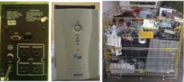
This paper presents a complete model of a single phase induction generator with a re-used Un-interrupted Power Supply (UPS), a push-pull inverter which is commonly used for PC network supply. Some papers [8]-[10] already studied the re-use of full PC supplies [8] or parts of them [9] [10] but the re-use of an inverter is the original approach developed in this study. Some examples of old components are shown in Fig. 1(a) and Fig. 1(b): wasted induction motors and standalone UPS together with a lot of different electronic devices which are disposed each year. As an example, [11] indicates that 14 to 20 billion PC’s were thrown away in 2006. It is shown in [12], that almost 52 billion of computers have been trashed or recycled in USA in 2010 for a total weight of 423 000 tons. Unfortunately, only 40% of them are recycled as incineration remains the PC final destiny in most of the cases. There is certainly room for a second-life of part of them!
So, the first section of this article describes the complete state-space model of the waste induction generator and UPS. The next section presents the design of the controller for this generation system. The last section gives experimental results and discussions.
Fig. 1(b) : Electrical supplies from a lot of wasted electronic devices III. MODELING OFINDUCTIONGENERATOR The classical well-known modeling of the 3-phase squirrel cage induction motor can be found in [13] with the stator voltage and rotor voltage equations. For this motor, the rotor voltages are equal to zero. In [6], the author had developed and modeled it as the single phase induction generator which forms four order state space equation with two component input vector (excitation voltage and output voltage). A complex model is obtained by adding of two capacitors; excited capacitor and output capacitor [6], [7]. This complex model had also valid both cases with and without capacitors. Consequently, the state space equation of the model without capacitor is given as [7]:
̇ = [ ] + [ ] (1) where u=[vsevso]Tis input vector
x=[ise, iso, irαirβ]Tis state space vector
[vrabc]=0 for a squirrel cage induction machine A. Modeling of the single phase IG with capacitors
Capacitors are used to compensate the reactive power of induction generator as shown in Fig. 2. The capacitor currents are added in (1) to model where the excitation and output voltage, vseand vsoare the state variables of new model.
= = −
= = − (2)
In (2), Ce, Co, iCe, iCo, ie, and iLare the excitation capacitor,
output capacitor, excitation capacitor current, output capacitor
current, input excitation current and load current, respectively.
Fig. 2. Induction generator with two capacitors for reactive power compensation
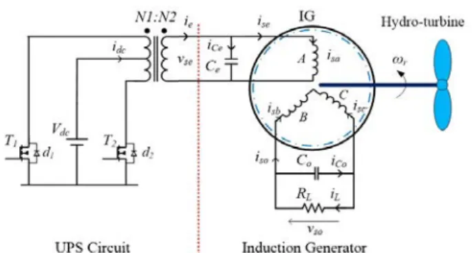
The excitation phase of the induction generator is connected to an UPS circuit as shown in Fig. 3. The push-pull DC/AC inverter is used in the UPS circuit to step-up the voltage from Vdc=24V DC to 110V AC and 230V AC. The
RMS value of the output voltage of the push-pull inverter depends on the battery DC voltage and its duty ratio for the switching MOSFET T1 and T2 and the transformation ratio of the transformer. The equivalent circuit of the transformer referring to the secondary winding is shown in Fig. 4.
A new state space model of the single phase induction generator with capacitors can be re-written as follows in [7]:
̇ = [ ] + [ ] (3) where xc=[vsevsoiseisoirαirβ]Tis new state vector and uc=ieis
the new input vector with its state and control matrices: [ ] = , [ ] = −1/ 0 0 0 0 −1/ 0 0 , [ ] = [1/ 0 × ] , [ ] = 00 −1/0 , [ ] = ⎣ ⎢ ⎢ ⎢ ⎢ ⎢ ⎢ ⎡ −√ √ − −√ −√ − √ ( ) − − √ ( ) ⎦ ⎥ ⎥ ⎥ ⎥ ⎥ ⎥ ⎤ [ ] = ⎣ ⎢ ⎢ ⎢ ⎢ ⎢ ⎡− 0 0 − 0 0 √ ⎦⎥ ⎥ ⎥ ⎥ ⎥ ⎤ with = − ( + ) + , = /2 − 2( + )( + ) − ( + ) = + , = + , = ( + ) + , = + + = /2 − 2( + )( + ) − ( + ))
B. Modeling of IG with Capacitor and UPS
Fig. 3. Complete system architecture with IG, 2 capacitors for reactive power compensation and UPS
Fig. 4. Equivalent circuit of transformer and IG
The secondary winding of transformer is connected to one phase of induction motor shown in Fig. 4 where the output voltage equation of at the secondary winding can be expressed as in (4):
= + + (4)
where Req= R’1+R2 and Xeq=X’1+X2, (Xeq=2πfLeq) R’1=(N2/N1)2R1, X’1=(N2/N1)2X1
In order to form the total state space equation of the system in Fig. 3, equations (3) and (4) are re-written as follows:
= − − 1 + 1 ̇ = [ ] + [ ]
(5)
The total state-space model of IG and UPS circuit is used to the describe behavior of the generation system where a new input vector, , and a new state variable, ie, are added.
̇ = [ ] + [ ] (6) where = is the system state vector, = is the system input vector and with
[ ] = [[ , ] [] [ ]] ,[ ] = − ,[ ] = [ ], [ ] = [−1/ 0 0 0 0 0], [ ] = [ ], [ ] = [1/ 0 × ]
The transfer function of input voltage, , to output voltage,
vso, can be determined from the total state space equation (6).
Replacing by kTrv1, then the transfer function of total system
can be defined as:
( ) = = ( − )( − ) … ( − )( − )( − ) (7) where z1,2and p1,..,7are zeros-poles of Ho(s), kTtotal gain
IV. MODELING OFUPSTOCONTROLIG
Fig. 5. Gate signal for T1 and T2 MOSFETs of the UPS
The re-used UPS, initially devoted to standalone computer supply includes a sine-modified inverter at the frequency of 100Hz. In our modified version, the driver circuit is based on the classical driver IC SG3524. It creates the 2 switching signals necessary to drive the 2 MOSFETs of the push-pull inverter as shown in Fig. 5. In order to use this UPS for isolated grid supply, the switching frequency is changed to 50Hz and its controller is re-design to maintain constant the RMS output voltage of the IG whatever the load. Fig. 6 shows the modified UPS used to control IG.
Fig. 7. PI Controller with error amplifier
Fig. 7 presents the arrangement of the error amplifier's compensation circuit, built in the IC SG3524. Setting the global behavior of the system involves positioning poles and zeros of Gc(s) in order to give the open-loop transfer function a
high DC gain for good output voltage regulation and a phase margin greater than 45° for stability margin [9]. The PI controller transfer function is expressed as in the standard form of (8):
( ) = − + (8) where zc=1/CR2, kc=R2/R1
Fig. 8. Asymptotic Bode plots for controller design
The zeros z1,2 and poles p1,2of Ho(s) can be cancelled one
by each other. The overall open loop transfer function is written in (9). The RMS voltage control of the induction generator is performed by Gc(s) and characterized by the Bode
plots in Fig. 8. In a classical manner, the controller zero is used to cancel pole p7of Ho(s), integral action to cancel the steady
state error and its proportional gain is used to set the crossover frequency Fcat a desired value.
( ) = ( ) ( ) (9) V. NUMERICALAPPICATION ANDEXPERIMENTS The induction generator operates in the following conditions: rotational speed of IG is Nr=1540 rpm of course over the synchronous speed, nominal load resistance is RL=
220Ω which emulates a motor load at its nominal power, PWM
duty ratio of UPS is d=20%, excitation capacitor is Ce=10mF
while the output capacitor is Co=5mF and the battery voltage Vdc=25.9V. The capacitor values are determined by calculating
the required reactive power of the IG. The motor parameters and transformer are given in appendix.
Fig. 9 shows the simulation results of whole system, single-phase induction generator SPIG, car battery and UPS. The corresponding experimental results given in Fig. 10 which are in good agreement for different operational conditions validate the simulation results.
Fig. 9. Simulation results of output voltage, Vso, battery current, Idc, excitation
voltage, Vse, and excitation current Ise
Fig. 10. Experimental results of output voltage, Vso, battery current, Idc,
excitation voltage, Vse, and excitation current Ise
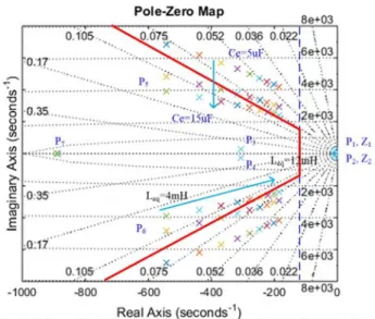
Fig. 11 shows the location of the poles and zeros map of the transfer function Ho(s). Rotor resistor increases with
temperature, will only slightly influence the location of pole P1, P2which are always compensated by zeros Z1and Z2. This
behaviour does not affect system stability. Ho(s) includes an
excitation capacitor, Ce, and a transformer equivalent
inductance, Leqwhich vary while the other parameters are kept
constants. It can be seen that their variations could affect the system performances. For example, when the input capacitor is increased, the damping ratio decreases. Besides, a higher
inductance value makes the pole move towards to the origin. These two parameters create complex conjugated poles p5 and p6, whose very low damping ratio may lead to high overshoot. But they can be turned into design parameters: Setting a chosen open loop bandwidth below -100rad/s and a damping ratio higher than 0.1 will lead to Leq< 5mH and Ce>10uF.
Fig. 11. Pole-Zero Map of Ho(s) for Leqand Cevarying
Fig. 12 shows the pole and zero map of Ho(s) when the load
RLchanges from 85Ω to 255Ω and the output capacitor from
0.5uF to 6.5uF. With Co=6.5uF, the conjugated poles P3 and
P4 still move inside the red designed location (bandwidth>100 rad/s and damping ratio>0.45). RL and output capacitor Co
values can be defined as 85Ω <RL<255Ω and Co< 6.5uF.
Fig. 12. Pole-Zero Map of Ho(s) for RLand Covariations
Bode plots of the open loop transfer function T(s) are shown in Fig. 13. They have high dc gain to regulate the RMS value of the output voltage and the crossover frequency is set by the controller gain kc, it remains far below the switching
frequency. The phase margin at the crossover frequency is greater than 45o. This result confirms that a simple PI controller is successful for the control of the RMS output voltage of this
induction generator. Fig. 14 shows the simulation of whole system induction generator with a simple pole place controller. The induction generator was subjected to a step load change 220Ω to 150Ω. The output voltage, Vso, output current, Iso,
excitation voltage, Vse, and excitation current, Iseare shown.
Fig. 13. Overall open loop frequency response of T(s)
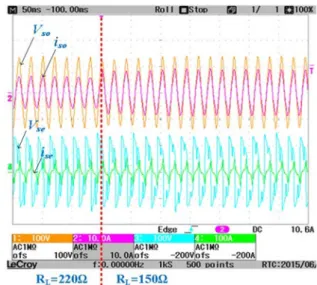
The prototype of IG, UPS, car battery and the control scheme were assembled together in order to verify the performance of this original type of energy generation system only based on disposed components. A step down transformer is used to step down output voltage of generator and connected to a rectifier for obtaining the feedback signal. The RMS value of feedback signal can be measured from the output of fullwave rectifier with its appropriated filter capacitor. This value is approximately equal to maximum of value of input signal where the RMS value can be obtained. The induction generator was subjected to a step load change 220Ω to 150Ω and its output voltage response is recorded, shown in Fig. 15. The settling time of RMS output voltage is about 150ms and its frequency remains the same as excited voltage which is 50Hz.
Fig. 14. Simulation time response of the output voltage of the IG with re-used UPS during load change from 220Ω to 150Ω
Fig. 15. Experimental time response of the output voltage of the IG with re-used UPS during load change from 220Ω to 150Ω
VI. CONCLUSION
Pico-hydro generation using disposed and wasted components, especially a 3-phase squirrel cage induction motor and a UPS, has been presented in this paper. First the whole system architecture and state-space model of the 7th order was described. Some suggestions about the total system sizing were made using the Zero-Pole placement analysis. A PI controller has been designed in order to control the output voltage of the induction generator. The controller of a re-used UPS has been modified and connected to the excited phase. Test results have shown that the induction generator and PI controller exhibits good RMS output voltage regulation and adequate transient response to the step-load change. This research work is suitable for electricity application in rural areas of developing countries where the cost of installation must be very low and where only disposal UPS, car battery and induction motors can be found in large quantities at an affordable price.
Future work will deal with higher power induction machines, resonant controllers for non-linear loads such as the rectifiers embedded in smartphone chargers, TV and other home appliances.
ACKNOWLEDGMENT
The authors would like to warmly thank M. Olivier DURRIEU from LAPLACE for his valuable contribution.
REFERENCES
[1] S.S Murthy, "a novel self-excited self-regulated single phase induction generator," IEEE Transactions on Energy Conversion, Vol. 8, No. 3, September 1993
[2] O. Ojo and I. Bhat,"An analysis of single phase self-excited induction generators," IEEE Transactions on Energy Conversion, Vol. 10, No. 2, June 1995
[3] T.F. Chan and L.L. Lai, "Single-phase Operation of a Three-phase Induction Generator Using a Novel Line Current Injection Method, "
IEMDC'03, Machines and Drives Conference, June 2003
[4] S.S. Murthy, U.K. Kalla and G. Bhuvaneswari, "a novel electronic controller implementation for voltage regulation of single phase self-excited induction," IEEE Industry Applications Society Annual Meeting
(IAS), October 2010
[5] R. Pena; J.C. Clare, and G.M. Asher, "A doubly fed induction generator using back-to-back PWM converters supplying an isolated load from a variable speed wind turbine," in Proc. IEE, Electric Power Applications, vol. 143, pp 380-387, 1996
[6] U.K. Madawala, T. Geyer, J.B. Bradshaw and D.M. Vilathgamuwa, "Modeling and Analysis of a Novel Variable-Speed Cage Induction Generator," IEEE Industrial Electronics Society, vol. 59, pp. 1020-1028, 2012
[7] P. Chrin, P. Maussion, M. Pietrzak-David, B. Dagues, L. Bun, "Modeling of 3-phase Induction Machine as Single Phase Generator for Electricity Generation from Renewable Energies in Rural Areas, "
IEMDC'15, Machines and Drives Conference, pp. 405-411, 2015, Coeur d’Alene, USA
[8] Kim B., Cenni H., Roth Anastasia, Bun L., David M., Maussion P., “How to reuse PC power supply for renewable energy applications”,
European Power Electronics Conference, 2015, September, Geneva, CH
[9] [9] Rogers, D.; Green, J.; Foster, M.; Stone, D.; Schofield, D.; Abuzed, S.; Buckley, A., “Repurposing of ATX computer power supplies for PV applications in developing countries”, Renewable Energy Research and
Applications (ICRERA), 2013 International Conference on,
[10] [10] Rogers, D.; Green, J.E.; Foster, M.P.; Stone, D.A.; Schofield, D.; Buckley, A.; Abuzed, S., “ATX power supply derived MPPT converter for cell phone charging applications in the developing world”, Power
Electronics, Machines and Drives (PEMD 2014), 7th IET International
Conference on
[11] U.S. Environmental Protection Agency Office of Resource, “Conservation and Recovery Electronics Waste Management in the United States through 2009”, May 2011
[12] United Nations Environment Programme (UNEP), “Basel Conference Addresses Electronic Wastes Challenge, Nov. 2006”, http://www.unep.org/Documents.Multilingual/Default.asp?DocumentID =485&ArticleID=5431&l=en
[13] P. C. Krause, O. Wasynczuk, and S. D. Sudhoff, Analysis of Electric
Machinery and Drive Systems, 2nd ed. New York: Wiley-IEEE Press,
2002.
APPENDIX Motor Parameters
Rs= 10.75Ω : Stator phase resistance
Rr= 7.2 Ω : Rotor phase resistance
Lms= 0.397H : Stator magnetization inductance
Lls= 0.027H : Stator leakage inductance
Llr= 0.027H : Rotor leakage inductance
N=4 : number of poles P=300W : Rated power
V/U=127/220V : Rated Voltage (3-phase) Transformer Parameters
R1= 0.16Ω : Primary winding resistance
R2= 1.30Ω : Secondary winding resistance
N2/N1=4.58 : Winding ratio (three output level) L1=0.034mH : Inductance of the primary winding. L2=7.66mH : Inductance of the secondary winding.