Publisher’s version / Version de l'éditeur:
Vous avez des questions? Nous pouvons vous aider. Pour communiquer directement avec un auteur, consultez la première page de la revue dans laquelle son article a été publié afin de trouver ses coordonnées. Si vous n’arrivez pas à les repérer, communiquez avec nous à PublicationsArchive-ArchivesPublications@nrc-cnrc.gc.ca.
Questions? Contact the NRC Publications Archive team at
PublicationsArchive-ArchivesPublications@nrc-cnrc.gc.ca. If you wish to email the authors directly, please see the first page of the publication for their contact information.
https://publications-cnrc.canada.ca/fra/droits
L’accès à ce site Web et l’utilisation de son contenu sont assujettis aux conditions présentées dans le site
LISEZ CES CONDITIONS ATTENTIVEMENT AVANT D’UTILISER CE SITE WEB.
Paper (National Research Council of Canada. Institute for Research in
Construction); no. IRC-P-1612, 1988
READ THESE TERMS AND CONDITIONS CAREFULLY BEFORE USING THIS WEBSITE. https://nrc-publications.canada.ca/eng/copyright
NRC Publications Archive Record / Notice des Archives des publications du CNRC :
https://nrc-publications.canada.ca/eng/view/object/?id=11f59b37-ce0c-425e-a802-97e1a170daa2 https://publications-cnrc.canada.ca/fra/voir/objet/?id=11f59b37-ce0c-425e-a802-97e1a170daa2
NRC Publications Archive
Archives des publications du CNRC
For the publisher’s version, please access the DOI link below./ Pour consulter la version de l’éditeur, utilisez le lien DOI ci-dessous.
https://doi.org/10.4224/20375356
Access and use of this website and the material on it are subject to the Terms and Conditions set forth at
On measuring the shear strength of ice
TH1
~ 2 1 d National Research
Conseil
natsonaino. 1612
1
*
1
Council Canada
de
mhetches
Canadac , 2
BLDG Institute for lnstitut de
-- .- Research in recherche en
Construction construction
On Measuring the Shear Strength
of
Ice
by R.M.W. Frederking, O.J. Svec and G.W.
T
imcoAppeared in
Proceedings of the 9th International Symposium on Ice
Sapporo, Japan, August 23-27,1988 IAHR Committee on Ice Problems, Vol. 3 p. 76-88
(IRC Paper No. 1612)
Reprinted with permission NRCC 30756
L I B R A R Y
B I B L I O T H ~ Q U E
I R CL'analyse par la mCthode des ClCments finis de poutres soumises Zi des charges en quaue
points asyxnktriques a 6tC utilistk pour calculer les champs
de
contraintes internes
pour
d8fChents Cchantillons et diffkrentes gbmCmes d'application des charges. Les contraintes de
cisdement dCtamh&s d'aprks ces champs
de
contrahe diffdraient nettement de celles
cdcdies &ap& la thCorie de la poutre unique. Des exp5riences effectu6es en labratoire
avec des Cchantdlons de glace d'eau douee
h
gains columnaires ont montr6 que des valeurs
cshhntes Ctaient obtenues pourvu que les Cchantillons ~t les g&&tries &application des
charges ne varient pas au-del8 d'une plage pdcub2re. A
-10
OC
une dsistance au
cisaillement moyenne de
600
kPa a it6 dCt-k.
Des mesures sp&iales
adoptks
afin
de
r6duire la concentration des contraintes aux points d'application des charges ont entrahi un
accroissement de la dsistance au cisaillement moyenne qui est passee
B
1100kPa. Une
m6thode d'essai de cisaillement dans la glace bade sur
cettee&rience est proposCe.
Sapporo
ON MEASURING THE SHEAR STRENGTH OF I C E
R e Frederking and O.J. Svec Geotechnical Section
I n s t i t u t e f o r Research i n Construction G.W. Timco D i v i s i o n o f Mechanical Engineering
National Research Council of Canada Ottawa, Ontario, CANADA
K I A OR6 ABSTRACT
F i n i t e element a n a l y s i s o f beams subjected t o f o u r c p o i n t asymmetric l o a d i n g has been used t o c a l c u l a t e t h e i n t e r n a l s t r e s s f f e l d s f o r d i f f e r e n t specimen and 1 oading geometries. The shear stresses determi ned from these s t r e s s f i e l d s were s i g n i f i c a n t l y d i f f e r e n t from those c a l c u l a t e d from s i m p l e beam t h e o r y . L a b o r a t o r y experiments done on samples o f columnar-grained f r e s h w a t e r i c e showed t h a t consistent values o f shear s t r e n g t h were obtained provided specimen and 1 oading geometries d i d n o t vary beyond a p a r t i c u l a r range. A t - 1 r C an average shear s t r e n g t h o f 600 kPa was determined. Special measures taken t o reduce s t r e s s concentrations a t t h e l o a d a p p l i c a t i o n p o i n t s r e s u l t e d i n an increase o f t h e average shear s t r e n g t h t o 1100 kPa. Based on t h i s experience, a shear t e s t i n g method f o r i c e i s proposed.
IAHR Ice
Symposium 1988
Sapporo
I n t r o d u c t i o n
A n a l y t i c a l models o f i c e forces on s t r u c t u r e s have generally considered t h e i c e i n t h e i n t e r a c t i o n zone t o be under a u n i a x i a l o r m u l t i a x i a l compressive s t r e s s condition. It i s q u i t e possible, however, t h a t s i g n i f i c a n t p a r t s o f t h e i n t e r a c t i o n zone may be subjected t o b i a x i a l s t r e s s c o n d i t i o n s i n v o l v i n g t e n s i l e i n a d d i t i o n t o compressive stresses. Measurements o f shear s t r e s s a r e r e l e v a n t t o d e f i n i n g t h i s s t r e s s condition. Therefore i n f o r m a t i o n on shear s t r e n g t h i s necessary i n a n a l y t i c a l p r e d i c t i o n s o f i c e loads where t h i s t y p e o f f a i l u r e behaviour i s occurring. Shear-strength data a r e a l s o u s e f u l i n determining t h e f a i l u r e envelope o f i c e under m u l t i a x i a l s t r e s s conditions.
The shear s t r e n g t h o f i c e i s a d i f f i c u l t p r o p e r t y t o measure i n an unambiguous fashion. The techniques commonly used, d i r e c t shear, punching, o r torsion, create s t r e s s f i e l d s t h a t cannot be q u a n t i f i e d simply. Normally i t i s assuned t h a t a uniform shear s t r e s s i s generated on a plane o f f a i l u r e , b u t i n
many
instances indeterminate normal stresses a r e a l s o generated on t h e plane o f f a i l u r e . For example, Butkovich (1956) obtained values i n t h e ranges 500 t o 1200 kPa u s i n g t h e double shear technique, w h i l e Paige and Lee (1967) and Dykins (1971) obtained values i n t h e ranges 500 t o 1200 kPa and 100 t o 250 kPa r e s p e c t i v e l y f o r s i n g l e shear. I n a l l t h r e e cases, r e s u l t s were f o r f i r s t - y e a r sea i c e o f s i m i l a r s a l i n i t y and temperature. This l a r g e d i s p a r i t y i n r e s u l t s brings i n t o question t h e v a l i d i t y of t h e t e s t methods used i n t h e past. The o f f - a x i s s t r e n g t h t e s t (Pipes, 1973), i n which t h e specimen a x i s i s o r i e n t e d a t some angle t o t h e m a t e r i a l coordinate systems, has been used t o o b t a i n s t r e n g t h data under a l o a d i n g c o n d i t i o n w i t h t e n s i l e and compressive p r i n c i p a l stresses (shear).It produces b o t h normal and shear stresses on t h e f a i l u r e plane.
The asymmetric f o u r - p o i n t l o a d i n g method has been proposed as a means o f performing improved shear t e s t s (Iosipescu, 1967). This method was a p p l i e d t o an i n v e s t i g a t i o n o f g r a n u l a ~ s t r u c t u r e d f i r s t - y e a r i c e from t h e Beaufort Sea (Frederking and Timco, 1984) and t o columnarcgrained and f r a z i l sea i c e from Labrador (Frederking and Timco, 1986). Consistent r e s u l t s were obtained. This paper w i l l present t h e r e s u l t s o f f i n i t e element (FE) c a l c u l a t i o n s o f beam subjected t o fourcpoint asymmetric
loading. Strengths c a l c u l a t e d from t h e FE a n a l y s i s and simple beamtheory
supporo
w ~ l l
be conpared w i t h r e s u l t s o f l a b o r a t o r y t e s t s and a recommended c a l c u l a t i o n and t e s t method f o r shear proposed.Asymnetrical Four-point Bending Method f o r Shear
The asymmetrical f o u r - p o i n t bending method was used i n p e r f o r m i n g t h e shear t e s t s . Load i s appl i e d a t f o u r p o i n t s on a beam so t h a t a r e g i o n o f h i g h shear s t r e s s and low bending s t r e s s i s generated a t t h e m i d - s e c t i o n of t h e beam. The geometry o f l o a d a p p l i c a t i o n and r e s u l t i n g i d e a l i z e d shear forces and bending moments a r e i l l u s t r a t e d i n F i g u r e 1. The s h e a r c s t r e s s d i s t r i b u t i o n a t t h e c e n t r e plane, x
=
0,
i s assuned t o be p a r a b o l i c w h i c h gives a maximm shear s t r e s s ,+,
a t t h e mid h e i g h t o f t h e beamwhere P i s t o t a l a p p l i e d load, b i s specimen thickness, h i s specimen
1111,
/')Ir,
B A R U P P E R PLATEc
S P E C I M E Nl
x
I I I / J LOWER P P L A T E - a-
P -&P S H E A R FORCE D I A G R A M I + = B E N D I N G M O M E N T D I A G R A MF i g u r e 1. Asymmetric f o u r - p o i n t l o a d i n g apparatus and shear f o r c e and bending moment diagrams (from Frederk i n g and Timco, 1984).
IAHR
Ice Symposium 1988
Sappon,
h, and a r e l a t e s t o t h e l o a d i n g geometry. The specimen geometry proposed by Iosipescu, (1967) included notches i n t h e t o p and bottom surfaces of t h e beam a t t h e mid-plane, x = 0. This procedure has t h e e f f e c t of reducing t h e cross-sectional area subjected t o t h e shear s t r e s s and o f producing a nearly uniform shearcstress d i s t r i b u t i o n , provided t h a t each notch depth i s between 20
-
25% o f t h e specimen heigtit, h. For t h e notched beam, maxirmm shear s t r e s s i s g i v e n bywhere P,- a, and b a r e as defined f o r equation (1) and ho i s t h e n e t h e i g h t of t h e beam across t h e notches.
F i n i t e
Element
AnalysisA f i n i t e element analysis, u s i n g q u a d r i l a t e r a l 1 in e a r elements, was
employed t o examine t h e s t r e s s f i e l d i n t h e c e n t r a l r e g i o n of t h e t e s t specimens. L i n e a r e l a s t i c behaviour was assuned f o r t h e i c e ( e l a s t i c modulus 10 GPa and P o i s s o n ' s r a t i o 0.3) and t h e p l a n e s t r e s s (az
=
o) c o n d i t i o n appl ied. The factors of specimen depth, h, l o a d i n g p o s i t i o n , aand notch o r saw cut a t t h e c e n t r a l plane o f t h e beam were treated. A standard mesh of 66 elements along t h e l e n g t h of t h e beam and 20 elements over t h e depth was used f o r a l l t h e cases investigated. Only element s i z e and shape ( t r a p e z o i d a l f o r t h e notch and saw-cut) were varied. The stresses i n a l l cases a r e f o r an a p p l i e d l o a d o f P = 1080 N.
The r e s u l t s o f t h e f i n i t e element c a l c u l a t i o n s a r e summarized i n Table 1. Maximum v a l u e s of s h e a r s t r e s s , .cmax, and t e n s i l e stress, ul, a t t h e c e n t r e plane (x = 0) and l o a d i n g plane ( x = a x ) a r e presented f o r a v a r i e t y o f cases. F o r comparison s h e a r stress, .c c a l c u l a t e d from simple beam
XY
'
theory i s a l s o included. It can be seen t h a t t h e r e s u l t s f o r maxinum shear s t r e s s , s and a r e i n reasonable agreement f o r t h e two c a l c u l a t i o n
x Y
methods, i n t h e case of p l a i n beams.
F i g u r e 2 presents t h e s t r e s s d i s t r i b u t i o n s a t t h e c e n t r a l plane
( x = 0) of t h e beam f o r t h e case of beam depth h 100 mm and l o a d p o s i t i o n
a = 0.1. The l e f t hand p a r t o f t h e f i g u r e shows t h e stresses i n terms o f t h e Cartesian coordinate system (x, y ) and i n t h e r i g h t hand p a r t t h e same
s@poro
b l e
1
Calculated maxlmrrn shear and t e n s i l e s t r e s s u s i n q f i n i t e element a n a l y s i s (FE) and simple beam theory (SB) f o r v a r i o i s beam geometries and l o a d i n g p o s i t i o n s . Stresses, i n kPa, a r e f o r 50 mm t h i c k beams w i t h a nominal l o a d P = 1080 N. + h=70 mm h=100 mm h=140 mm p l a i n p l a i n V-notch saw-cut p l a i n eO.1SB
%y 3 90 27 0-
-
240 180 F E h x , x = O 340 2 50--
1780 ' 210 %ins x'QR 380 380--
350 350 ul, x-0 360 220..
..
130 150 ' h0.2 SB 310 220 300 300 150 FEhx,
F O
310 210 230 910 140 %i n* X" 270 310 300 310 3 10 ul, x=O 490 250 160 240 150s t r e s s e s have been converted t o p r i n c i p a l stresses, q a n d
%,
and maxinum s h e a r s t r e s s , rma, =( 4
-
u22)12. Note, t e n s i l e s t r e s s e s a r e t a k e n as p o s i t i v e . The FE a n a l y s i s produces values o f -40 kPa f o r s a t t h e beamXY
surface, whereas t h e v a l u e here should be zero. T h i s anomaly i n d i c a t e s t h a t t h e r e s u l t s o f t h e a n a l y s i s a t o r near a f r e e surface have t o be
STRESS, kPa STRESS
(COMPRESSION) (TENSION)
F i g u r e 2. Stress d i s t r i b u t i o n p l o t s a t c e n t r a l p l a n s (x
=
0)
o f a 100 mm deep beam i n t e r n o f ( a ) specimen coordinates(%,
and ), and ( b ) p r i n c i p a l s t r e s s coordinates (=,q
and%3.
~ o a n g p o s i t i o n a = 0.1.IAHR
Ice SymPosium
1988Snpporo
r n t e s p r c t e d w i t h some caution, F i g u r e 2 shows t h e s h e a r s t r e s s , r XY
'
d i s t r i b u t i o n detennined from t h e FE a n a l y s i s d i f f e r s s u b s t a n t i a l l y from t h e p a r a b o l i c d i s t r i b u t i o n assuned i n t h e simple beam theory (Equation I ) , even though t h e maxirmm values o f shear s t r e s s a r e s i m i l a r f o r t h e two c a l c u l a t i o n methods. The r e s u l t s a l s o s h w t h a t a c o n d i t i o n o f pure shear (ax
= u =
0 o rq
=- ? )
does n o t e x i s t a t t h e c e n t r a l plane, t h e r eY
i s i n f a c t a mean compressive s t r e s s o f 140 kPa on t h e plane o f l a r g e s t
s ma x (260kPa).
I n F i g u r e 3 t h e p r i n c i p a l stresses,
9
and4 ,
and zmx a r e p l o t t e d f o r two l o a d i n g positions, a = 0.1 and 0.2, f o r a 100 mm deep beam. F i g u r e 3a, f o r t h e stresses a t t h e centre plane, s h w s t h a t t h e s t r e s s d i s t r i b u t i o n s change s l i g h t l y and t h a t t h e maxirmm shear s t r e s s on t h e centre plane (x = 0) i s 250 kPa i n t h e case o f l o a d p o s i t i o n a = 0.1 versus 200 kPa f o r load p o s i t i o n 0.2. Figure 3b, f o r stresses a t t h e plane of l o a d a p p l i c a t i o n (x=
d), i n d i c a t e s t h a t b o t h d i s t r i b u t i o n s a r e generally s i m i l a r b u t t h a t , again, -rmax i s l a r g e r f o r l o a d p o s i t i o n a=
0.1. Note t h a t F i g u r e 3b a l s o i n d i c a t e s t h e presence o f a high shear s t r e s s j u s t b e l m t h e surface o f t h e beam and a high t e n s i l e s t r e s s on t h e opposite s i d e o f t h e beam a t t h e l o a d a p p l i c a t i o n plane (x=
aA).The s t r e s s d i s t r i b u t i o n s a t t h e c e n t r e plane f o r a 20 mm deep
90'
V-notch i n a beam o f depth 100 mm a r e presented i n F i g u r e 4. Note t h a t t h e n e t s e c t i o n d e p t h a t t h e notch, ho, i s 6 0 m I n t h i s case, rmX i n t h e notch i s uniform w i t h a maxirmm value o f 230 kPa. This s t r e s s i s s l i g h t l y l a r g e r t h a n t h e value o f 210 kPa obtained f o r an unnotched beam w i t h l o a d p o s i t i o n a = 0.2 (see Table 1). The s t r e s s d i s t r i b u t i o n s a t t h e l o a d i n g plane ( x
=
UA) were s i m i l a r t o those o f t h e un-notched beam.The s t r e s s d i s t r i k r t i o n s c a l c u l a t e d f o r t h e saw c u t case a r e n o t plotted, b u t i t can be seen i n Table 1 t h a t they gave a very high v a l u e f o r
r
max' There i s some q u e s t i o n as t o t h e accuracy o f t h e stresses c a l c u l a t e d a t t h e t i p o f t h e cut. It i s planned f o r f u t u r e research t o use h i g h e r o r d e r elements and a more r e f i n e d FE mesh, p a r t i c u l a r l y i n l o c a t i o n s o f s t r e s s concentration. Developnent o f a FE model capable o f approximating nonl i n e a r behaviour o f i c e might a l s o become necessary.
Sapporo
q
,
kPa a2, @a %OX 9 IcF'a-0 300 -300 0 -300 0
a) STRESSES AT CENTRAL PLANE ( x = 0 )
q,
kPa %, kpa T , , , ~ , kpab) STRESSES AT LOAD PLANE ( x = a
I )
F i g u r e 3. D i s t r i b u t i o n s o f p r i n c i p a l s t r e s s e s ,
q
and 42, a n d maximm s h e a r s t r e s s , f o r a p l a i n 1 0 0 mm d e e p beam w i t h l o a d F = 1080N.Test Method and Specimen Preparation
A t e s t apparatus has been b u i l t t o rep1 i c a t e t h e c o n d i t i o n s i n d i c a t e d i n F i g u r e 1. The d i s t a n c e of t h e o u t e r l o a d i n g p o i n t s (a b a l l i n each
IAHR Ice Sym~osium
1988
Sapporo
STRESS, kPa
' i g u r e 4. D i s t r i b u t i o n s o f p r i n c i p a l s t r e s s e s ,
q ,
and9 ,
and maximm shear stress,ha,
a t t h e c e n t r a l plane (x = 0) of a 100 mm deep beam w i t h 2 20 mm deep 90' notches.case), A, i s 150 mm from t h e c e n t r e 1 ine, x
=
0, Two s e t s o f notches a r e provided i n each p l a t e a t 1 5 and 30mm
d i s t a n c e ( a = 0.1 and 0.2 r e s p e c t i v e l y ) from t h e centre. A t these i n n e r l o a d i n g p o s i t i o n s a b a r i s used t o d i s t r i b u t e t h e l o a d across t h e w i d t h o f t h e specimen. The upper p l a t e , through which t h e l o a d P i s applied, i s f r e e t o r o t a t e about t h e 1 oad-appl i c a t i o n point. Loading was c a r r i e d o u t u s i n g a 50-kN capacity f i e l d p o r t a b l e conpression t e s t e r designed and b u i l t a t t h e National Research Council o f Canada. The machine has a screw d r i v e actuator. A1 1 t e s t i n g was done a t a nominal a c t u a t o r r a t e o f 0.5 mm sml.Continuous records o f l o a d versus time were made f o r each test. I n a few cases, high speed 16 mm movie f i l m were a l s o taken, a t a r a t e o f 400 frames/s. The purpose o f t h e f i l m i n g was t o d e t e c t t h e l o c a t i o n of f a i l u r e i n i t i a t i o n and t o f o l l o w i t s progress.
A 60 mm t h i c k columnar-grained f r e s h w a t e r i c e sheet (C2, according t o IAHR, 1986 c l a s s i f i c a t i o n o r S2 according t o Michel and Ramseier, 1971) was g r w n i n t h e I c e Test Basin o f NRC's Hydraulics Laboratory i n Ottawa. The t o p 10 mm o f t h e i c e sheet was discarded, l e a v i n g uniform columnar i c e w i t h an average g r a i n diameter o f 3 mm. Specimens were c u t t o rough dimensions on a band saw and t h e n planed on a power p l a n e r t o f i n a l nominal dimensions
s*m
350 nun length, 50 mm thickness and 70, 100 o r 140 mm depth. A d d i t i o n a l l y , some o f t h e 100 mm deep specimens were prepared w i t h a p a i r of 90' notches o r 2 mm wide saw cuts a t t h e c e n t r a l plane of t h e beam
( x
=
0). These notches o r c u t s each extended t o a depth o f about 20 mm, l e a v i n g a net s e c t i o n depth o f about 60 mm. The l o n g a x i s o f t h e columnar g r a i n s were always normal t o t h e l a r g e s t faces. Specimen p r e p a r a t i o n and t e s t i n g was c a r r i e d out a t a temperature o f -10'C+
1'C.Test Results and Discussion
Tests were performed on a t o t a l o f 57 beams. Table 2 summarizes a l l t h e cases examined. The main parameters v a r i e d were beam depth, h, l o a d position, a, notching and saw c u t s o f beams, and t h e absence o r presence of s t r e s s r e l i e f m a t e r i a l under t h e l o a d i n g bars. Force time curves f o r
repeat t e s t s done on a 100 mm deep beam w i t h l o a d p o s i t i o n a = 0.1 a r e presented f n F i g u r e S(a). The general consistency of t h e t e s t r e s u l t s can be seen. These curves a l s o shcw t h e e f f e c t s o f l o c a l cracking and spa11 i n g o f t h e specimen a t t h e l o a d i n g p o i n t s when no s t r e s s r e l i e f i s used a t t h e l o a d i n g bars. The small decreases i n l o a d occur due t o r e l a x a t i o n i n t h e t e s t system which i s l o a d i n g a t a nominally constant r a t e o f displacement. T h i s behaviour was not noted i n a previous a p p l i c a t i o n o f t h i s t e s t method t o s a l i n e i c e ( F r e d e k i n g and Timco, 1984, 1986). Figure 5(b), by contrast, presents r e s u l t s w i t h a l o c a l s t r e s s r e l i e f m a t e r i a l under t h e l o a d i n g points. The f i r s t obvious f a c t o r i n t h i s case i s t h e smooth monotonic increase i n l o a d up t o f a i l u r e . Also, s i g n i f i c a n t l y h i g h e r f a i l u r e loads were obtained. This d i f f e r e n c e i n l o a d i n g behaviour was a l s o observed i n t h e high speed 16 mm filming, i n which small pieces o f i c e Table 2 Summary o f cases examined i n t e s t program
X, tested; S, t e s t e d w i t h s t r e s s r e l i e f m a t e r i a l
-
84-
Beam h=70 mm p l a i n a=
0.1 X, S a = 0.2 X <-
h=140 mm p l a i n X X h=100 mm p l a i n X,s
X V-notch--
X,S saw-cut X,Sx,s
-- --
IAHR
Ice
Symposium 1988Sapporo
6000
a) I
TIME,
s
F i g u r e 5. P l o t s o f f o r c e versus time f o r 100 mm deep beams w i t h l o a d
p o s i t i o n a
=
0.1; (a) no s t r e s s r e l i e f m a t e r i a l under l o a d i n g bars, (b) stress r e l i e f m a t e r i a l under b a n , ( s o l i d l i n e s-
bake1 i t e ),
(dashed 1 ines-
cardboard).c o u l d be seen s p a l l i n g o f f t h e beam when no s t r e s s r e l i e f m a t e r i a l was used.
P l a i n specimens f a i l e d w i t h a s i n g l e crack which extended from l o a d b a r t o l o a d bar. The V-notched and saw-cut specimens f a i l e d w i t h two cracks, each extending from t h e l o a d b a r t o t h e opposite notch o r saw-cut t i p . The h i g h speed f i l m was examined t o see whether t h e p o i n t o f cradt
i n i t i a t i o n and d i r e c t i o n o f propagation could be detected, I n t h e case of t h e plane beam, crack i n i t i a t i o n and propagation occurred i n l e s s t i m e t h a n t h e 11400 s (2.5
ms)
between frames. I n t h e case o f t h e V-notch, i t appeared t h a t t h e crack i n i t i a t e d a t t h e b a r and then ran t o t h e notch t i p . Propagation t i m e i n t h i s instance was l e s s t h a n 5ms.
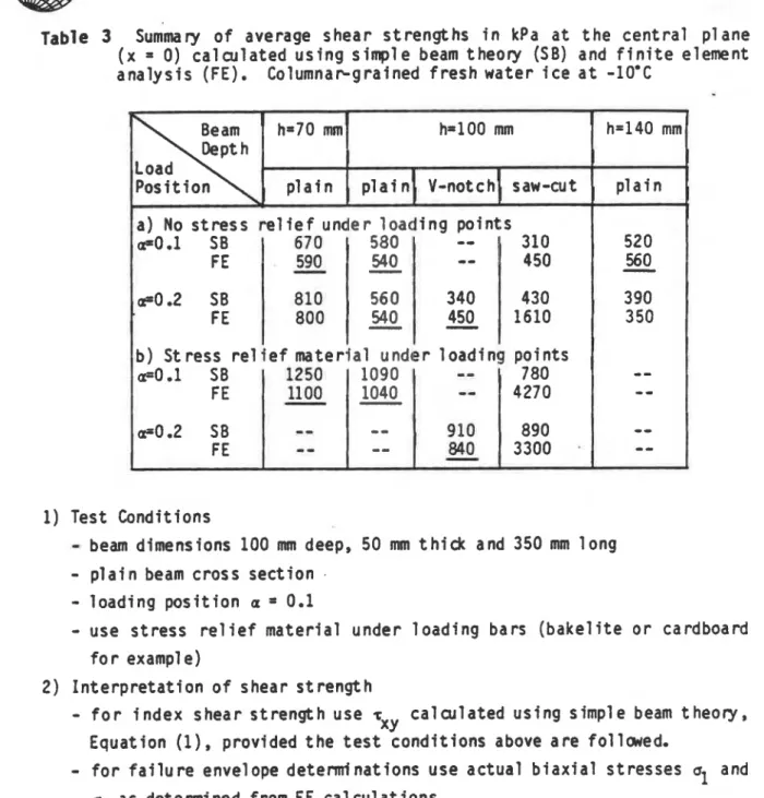
The t e s t r e s u l t s were analysed f o r shear s t r e n g t h and t e n s i l e s t r e n g t h u s i n g simple beam theory (Equations(1) and ( 2 ) ) and f i n i t e element a n a l y s i s (Table 1). I n terms o f d e r i v i n g a shear s t r e n g t h from t h e data, t h e most c o n s i s t e n t r e s u l t s were o b t a i n e d u s i n g t h e maxim. shear strength,
bax,
determined from t h e f i n i t e element analysis. This can be seen i n Table 3 which summarizes a l l t h e t e s t results.S*IO
There were no instances o f t h e f a i l u r e plane propagating towards o r away from t h e zone o f high t e n s i l e s t r e s s opposite t h e l o a d i n g points. Therefore calculated t e n s i l e s t r e n g t h s a r e not presented here even though t h e f i n i t e element c a l c u l a t i o n s would i n d i c a t e t h a t they were high, p a r t i c u l a r l y f o r t h e 70 mm deep beams (see Table 1). F i g u r e 3 and Table 1
a l s o s h w high shear stresses under t h e l o a d i n g p o i n t s ( x
=
+ a ~ ) b u t these have been disregarded i n subsequent c a l cul ations o f shear strength. They were exami ned, but produced 1 ess c o n s i s t e n t results.The r e s u l t s o f Table 3 shcw t h a t t h e r e i s b e t t e r consistency i n t h e shear strength values when they a r e evaluated u s i n g a f i n i t e element a n a l y s i s r a t h e r than simple beam theory, p a r t i c u l a r l y i n t h e case of plane beams and V-notched beams. The p l a i n beams o f depth 70, 100 and 140 mm and l o a d p o s i t i o n a = 0.1 as w e l l as t h e 100 mm deep beam w i t h l o a d p o s i t i o n
a
=
0.2 a l l had remarkably s i m i l a r r e s u l t s when evaluated u s i n g t h e f i n i t e element analysis. These r e s u l t s a r e u n d e r l i n e d i n Table 3. It can a l s o be seen t h a t i n t r o d u c i n g a s t r e s s r e l i e f m a t e r f a l r e s u l t s i n about a d o u b l i n go f t h e shear strength. T h i s r e s u l t i m p l i e s t h a t f o r no s t r e s s r e l i e f m a t e r i a l under t h e l o a d i n g p o i n t s d i f f e r e n t stresses a r e produced t h a n those fndicated by t h e f i n i t e element analysis. Some i n d e n t a t i o n of t h e bars i n t o t h e i c e was noted. This i n d e n t a t i o n could induce h i g h t e n s i l e stresses i n t h e beam and i n i t i a t e premature f a i l u r e under t h e l o a d i n g bars.
S u m
ry
anil
Rectnmiendat ions
, Shear strengths c a l c u l a t e d from f i n i t e element a n a l y s i s o r simple beam
theory give s i m i l a r r e s u l t s f o r plane and 90' V-notch beams. The shear s t r e s s d i s t r i b u t i o n s c a l c u l a t e d w i t h f i n i t e element analysis, however, a r e more accurate t h a n those c a l c u l a t e d u s i n g simple beam theory. Experiments
performed on columnar-grained f r e s h water i c e were used t o evaluate t h e c a l c u l a t i o n methods. Test r e s u l t s i n d i c a t e d t h a t keeping beam dimensions and loading p o s i t i o n s w i t h i n l i m i t s determined by t h e t e s t s allowed c o n s i s t e n t shear s t r e n g t h values t o be determined.
The f o l l w i n g recomnendations a r e made f o r t e s t i n g and i n t e r p r e t i o n of shear strength:
IAHR
Ice Symposium
1988
sapporn
Table
3
~um'ma ry o f average shear s t r e n g t h s i n kPa a t t h e c e n t r a l plane ( x = 0) c a l c u l a t e d u s i n g simple beam theory (SB) and f i n i t e element a n a l y s i s (FE). C o l u m n a ~ g r a i n e d f r e s h water i c e a t -10.C1) Test Conditions
-
beam dimensions 100 mm deep, 50 mm t h i c k and 350mm
l o n g-
p l a i n beam cross s e c t i o n .-
l o a d i n g p o s i t i o n a=
0.1-
use s t r e s s r e l i e f m a t e r i a l under l o a d i n g bars ( b a k e l i t e o r cardboard f o r exampl e)2) I n t e r p r e t a t i o n o f shear s t r e n g t h
-
f o r i n d e x shear s t r e n g t h use r c a l c u l a t e d u s i n g simple beam theory, XYEquation
( I ) ,
provided t h e t e s t c o n d i t i o n s above a r e f o l l w e d .-
f o r f a i l u r e envelope determinations use a c t u a l b i a x i a l stressesu1
andu2
as determined from FE cal culations.Ack now1 edgements
The authors would l i k e t o acknwledge t h e assistance o f F r a r q o i s C a r r i e r , Summer Assistant, i n performing t h e f i n i t e element c a l c u l a t i o n s , and J. N e i l and R. Bowen, Technical O f f i c e r s , National Research Council o f Canada i n a s s i s t i n g w i t h t h e testing.
Sapporo
Butkovich, T.C. 1956. S t r e n g t h o f sea ice. Snow, I c e and Permafrost Research Establishnent, Research Report RR-20. W i 1 lamette, I 1 1 i nois, 15 p.
Dykins, J.E. 1971. I c e e n g i n e e r i n g
-
m a t e r i a l p r o p e r t i e s o f s a l i n e i c e f o r a l i m i t e d range o f conditions. Naval C i v i l Engineering Laboratory, Technical Report R720, P o r t Hueneme, C a l i f o r n i a , 96 p.Frederking, R.M.W. and Timco, G.W. 1984. Measurement o f shear s t r e n g t h o f granul ar/discontinuous-columnar sea ice. Cold Regions Science and Technology, Vol. 9, pp. 215-220.
F r e d e h i n g , R., and Timco, G.W. 1986. F i e l d measurements o f t h e shear s t r e n g t h o f columnar-grai ned sea ice. Proceedings of I A H R I c e Symposium 1986, Iowa C i t y , Iowa, 18-22 August 1986, Vol. 1, pp. 279-292.
IAHR, 1986. IAHR
-
Recommendations on t e s t i n g m e t h o d s o f ice, 5 t h r e p o r t o f Working Group on T e s t i n g Methods i n Ice. IAHR I c e Symposium, Iowa C i t y , Iowa, 18-22 August 1986, Vo1. I I I, pp. 595-599.Iosipescu, N. 1967. New a c c u r a t e method f o r s i n g l e shear t e s t i n g o f metals. Journal o f M a t e r i a l s , Vol. 2 ( 3 ) , pp. 537-566.
Michel,
B.,
and Ramseier, R. 1971. C l a s s i f i c a t i o n of r i v e r and l a k e ice. Canadian Geotechnical Journal, Vol. 8, No. 1, pp. 36-45.Paige, R.A. and Lee, C.W. 1967. P r e l i m i n a r y s t u d i e s on sea i c e i n Mdtlurdo Sound, A n t a r c t i c a , d u r i n g "Deep Freeze 65". Journal of Glaciology, Vol. 4
(46), p. 515-528.
Pipes, R. 1973. The o f f - a x i s s t r e n g t h t e s t f o r a n i s o t r o p i c m a t e r i a l s . J. Comp. Mat., Vol. 7, p. 246-256.